Jetmaster QUADRO User manual
1.ODQ.1A
ALL INSTRUCTIONS TO COMPLY WITH AS/NZS2918:2001
This appliance has been tested to AS/NZS 2918:2001 - by Spectrum Laboratory (Report 0580)
JETMASTER QUADRO OUTDOOR WOOD FIRE & BBQ COOKING GRILL
INSTALLATION INSTRUCTIONS TYPICAL IN-BUILT MASONRY BLOCK
03/03/2020
IMPORTANT: Read all instructions carefully before starting installation.
Failure to follow these instructions may result in a fire hazard and will void the warranty.
Masonry Definition: Solid Concrete, Concrete Block, Brick, Hebel Block/Panel
Consult The Fireplace Ltd or your local agent for any variation of the installation specified below
1.ODQ.1B
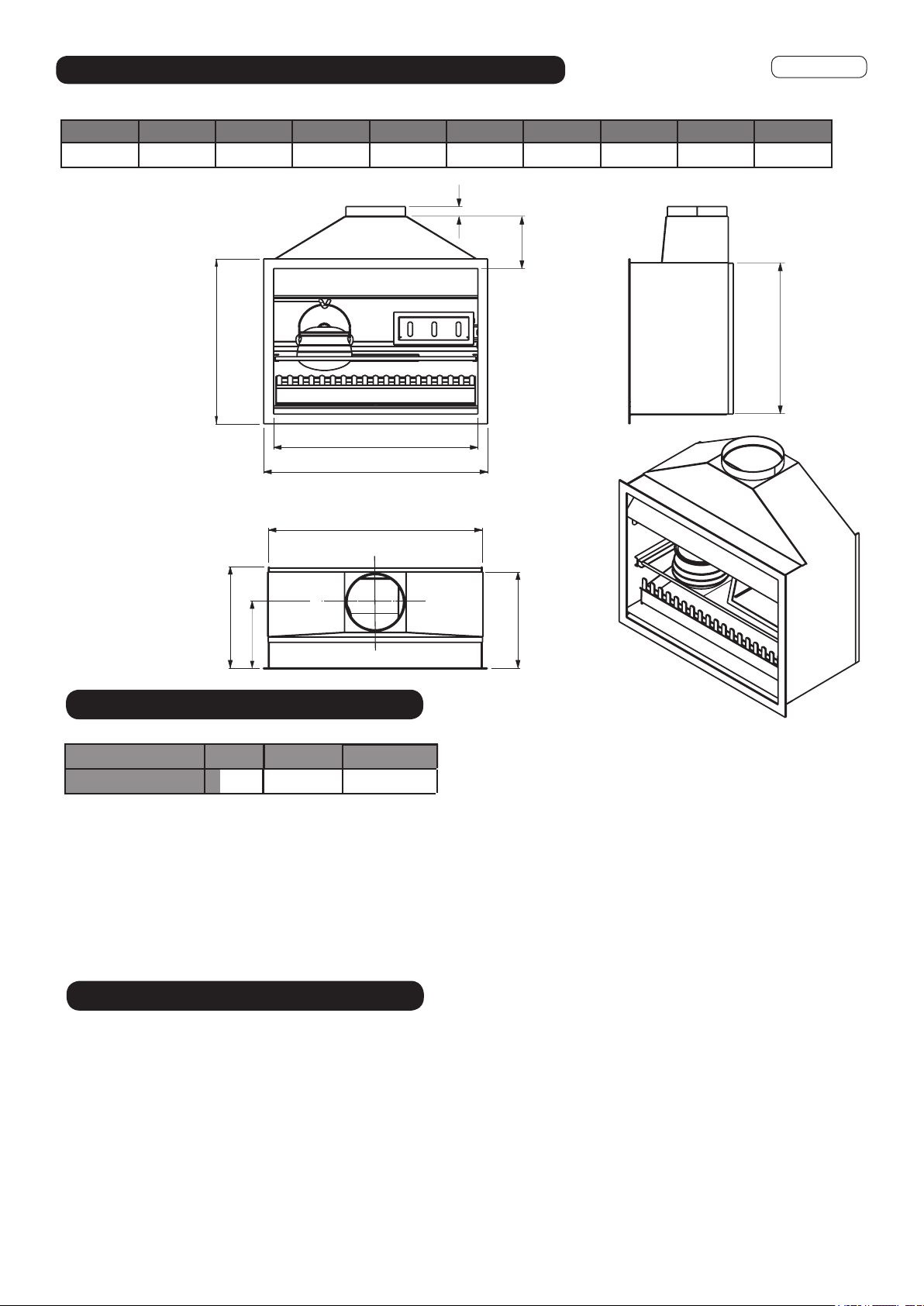
Table 1
Drawings Not To Scale
Dimensions in mm
A A1 A2 B B1 C D E F Y
1050 1150 1100 502 530 850 300/400 240 800 350
Fig. 1
C
E
50
D
A
A1
A2
B1
Y
F
D
B
MODEL A B + recess C + Base
1050 1400 760 + recess
Please note that these dimensions (based on 75mm ACC Block margins) are the absolute minimum sizes - widths (A & C) maybe
increased if desired.
IMPORTANT: Jetmaster firebox is raised 500mm and must be seated on top of a 75mm hebel sheet which is placed on top of a
steel structure or masonry blocks. A TIMBER BASE IS NOT ACCEPTABLE
The appliance, gather, flue and hebel panel weighs approx 400kg. Ensure the base structure can withstand this load.
IMPORTANT:
THE APPLIANCE MUST BE INSTALLED AT LEAST 1200mm AWAY FROM COMBUSTIBLE ADJACENT WALLS (EG. HOUSE)
MINIMUM CAVITY SIZE
1400 + 500 NOTE: Minimum Recess = 40mm / Maximum Recess = 100mm
FIREBOX INSTALLATION
1. Locate and position firebox, fit and seal gather in cavity using fire cement (exhaust cement) and bolts (supplied), to the
firebox. Note: Pop rivet back of gather to firebox if required (refer to Cross Section).
2. Please note that the firebox MUST be positioned onto 25mm high non-combustible spacers (eg Hebel or NCB) this is
to ensure the bottom flange of the box is level with the concrete or Hebel base for the appliance to sit on.
3. Earthquake restraints may be positioned by drilling through firebox into the floor protector, in a position midway beneath the
log-pan. Two 6mm dynabolts or similar will suffice. Do not over tighten and deform firebox.
4. Attach rock wool (supplied) to the sides of the firebox and gather (using fire cement). DO NOT BLOCK OFF the air entry
between the inner flue pipe and flue pipe casing or the air circulation between the vent holes in the cavity.
5. Refer to page 5 of this document for minimum hearth sizes. Please note, a hearth is not required when the floor surface
below the fire is non combustible ie: concrete pavers, etc.
JETMASTER BOX DIMENSIONS
Appliance must sit on a
non-combustible base eg. 75mm
Hebel or 100mm concrete.
40mm packers are required.
Allow 5mm gap between plaster and flange to
ensure stainless steel cover can be fitted to the box.
DO NOT PLASTER OVER THE FLANGE
FOR DETAILS OF FLOOR PROTECTION (HEARTH )
SEE PAGE 5 OF THIS DOCUMENT
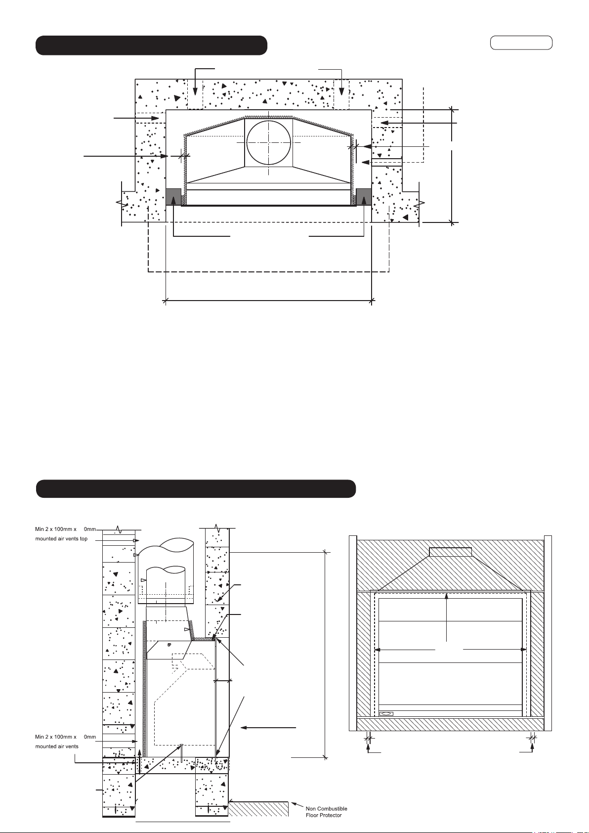
1.ODQ.3C
min. 25mm clearance 25
25 min. 25mm clearance
B + recessed
Masonry or Hebel block
minimum ‘A’
‘X’ - Refer to Table 2 for Floor Protector dimension
RECESS REQUIRED (40mm Min. 100mm Max)
‘Y’ - Refer to Table 2 for
Floor Protector dimension
Air Vent Air Vent
min. 2 x 100 x 200mm wall of floor
mounted air vents top and bottom
Jetmaster
Flange
Fig. 4
Drawings Not To Scale
Fig. 2
PLAN
CROSS SECTION
B + recessed
Concrete Lintel
Secure firebox with 2 x 6mm
dynabolts for earthquake
restraints
or Hebel Block
RECESSED REQUIRED
40mm Min. - 100mm Max recess
Rock-wool
insulation
Allow 5mm gap around all
four sides of the firebox to
fit Stainless Steel cover &
allow for firebox
expansion.
Fit 40mm Hebel packers
placed under the appliance
IMPORTANT
No combustible material into chimney chase
20
20
C- Dtemporary lintel height
*A minimum 75mm thick Floor protector is only required if finished surface is combustible e.g: timber decking
Please note that these dimensions (based on Masonry margins) are the absolute minimum sizes - widths (A & B) maybe
increased if desired.
If you intend on recessing the firebox, please add the recess value to Dimension ‘B’. MINIMUM RECESS = 40 / MAXIMUM
RECESS = 100mm
It is important to ensure the Jetmaster firebox is seated at the required finished floor protector level.
DO NOT COVER AIR VENTS WITH MESH - as this reduces air flow, use specific external air vent covers that provide sufficient
air.
Allow 5mm gap around all four sides of the firebox to fit the Stainless Steel Weather Cover. i.e. do not plaster
up to the flange of the firebox, see Fig 4.
Fig. 3
Non-combustible raised floor
protector must be 75mm Hebel
or 100mm concrete.
Appliance must sit on a
non-combustible base eg. 75mm
Hebel or 100mm concrete.
40mm packers are required

Drawings Not To Scale
1.ODQ.3D
Air Ventilation Through Top Flashing
Fig. 6
50 25
25
120mm
minimum
Drip
Line
Spigot flashing to suit
flue pipe casing
Non combustible material
Hebel Block or 12mm
Promatect H board or
similar under the flashing
120mm
minimum
Oversized casing cover
is necessary
Drip
Line
Air
Vent
NOTE: Air Vents to be min 2 x 80mm diam. or equal square or rectangle shape
area. These must be bird & rodent proofed with permanently fixed screens.
CHIMNEY CHASE VENTILATION
Air Ventilation Through Chimney Chase
Fig. 5
FLUE INSTALLATION
1. Install first length of flue pipe crimped end down, inside gather collar. Rivet flue pipe in 3 places around gather collar. Place bottom
flue spider bracket around gather flue pipe collar, secure in position by tightening up coach bolt/screw (supplied).
2. Install second length of the flue pipe crimped end down and fix by riveting in at least 3 places around the flue pipe joint.
3. Install first length of the flue pipe casing by positioning on installed bottom flue spider bracket crimped end up.
4. Position flue spacer at the flue pipe joint.
5. Repeat steps 1 - 4 to the required flue system height of 3.6m.
6. The last length of flue pipe needs to extend past the flue pipe casing by at least 150mm or flush with the top of the casing cover spigot
when fitted - sizing/measuring and cutting down should be carried out prior to the flue pipe casing being fitted over the flue pipe.
7. Before fitting casing cover, place the spider in opposition with the spider post facing down between the flue pipe and flue pipe casing.
Secure spider in position. Place the casing cover over the flue pipe, press down firmly onto the spider. Check airway around the
casing cover is clear, then secure in position using three stainless steel rivets.
8. Fit cowl to top of flue - DO NOT RIVET IN POSITION. In high wind areas, it is recommended that the cowl be secured in position with
a stainless steel self tapping screw, this will enable the cowl to be removed for cleaning. Discuss Bird Proofing needs with your
installer. N.B. In extreme wind areas it may be necessary to consult The Fireplace Ltd or your local agent for further technical
assistance.
9. If flue is concealed in a chase, allow for air vents (2 x 80mm diam. or equivalent) at the highest possible point on the chimney chase or
alternatively, allow a min 25mm air space between the casing cover spigot and the outer casing. Refer to Figure 5 & 6.
3000
or less
3000
More than 3000
600 min.
3000
increase as necessary
until nothing within
3000mm of flue top
Any nearby structure
increase from 1000mm
minimum until clear within
3000mm of flue top
MINIMUM HEIGHT OF FLUE SYSTEM EXIT
HEIGHT
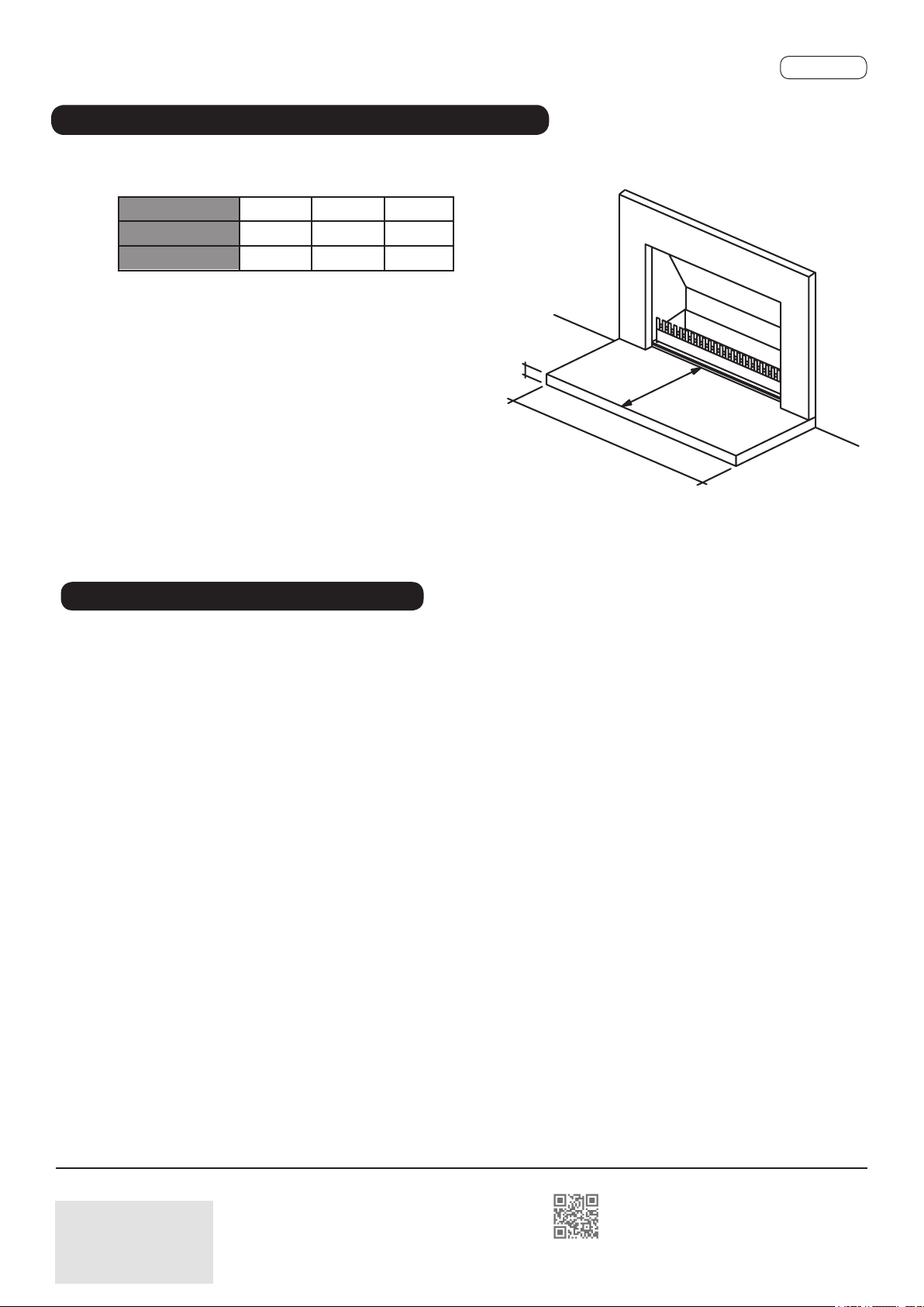
1.ODQ.3E
A
B
C
Dimensions in mm
If the appliance is installed at floor level the appliance and
hearth must be installed as outlined in AS/NZS 2918:2001.
C1.3.3.3.(c). The base of the firebox and floor protector must
*A minimum 75mm thickness refers only to Hebel Block.
Minimum 100mm thickness required if poured concrete.
MINIMUM FLOOR PROTECTOR
Head Office & Showroom
12 Tawari St, Mt Eden, Auckland
Ph: 09 623 6990
thefireplace.co.nz
Floor Protecter A B C
Raised 500mm 1400 800 *75
Floor Level 1400 1000 75
Table 2
GENERAL MAINTENANCE
▪ When the fire is not in use, ensure the stainless steel cover is fitted at all times. This will assist in protecting the firebox.
DO NOT attach the cover when the fire is in use.
▪ This fire is NOT warranted against rust.
▪ A seasonal touch-up is recommended. Simply remove surface rust with some steel wool and repaint using Black VHT paint
(available from your nearest showroom). Please ensure all areas around the firebox are protected when re-painting.
Table of contents
Popular Grill manuals by other brands


Kenmore
Kenmore 415.16123800 Use and care guide

Camp Chef
Camp Chef PG24CLAU Warning & instruction booklet

Tucker Barbecues
Tucker Barbecues GTR Series Assembly, installation and operating instructions

Monogram
Monogram ZGG540NCP1SS owner's manual

Equipex
Equipex Sodir Savoy Operation manual

Gaggenau
Gaggenau VR 414 610 use and care manual


