Jetter JHN Series User manual

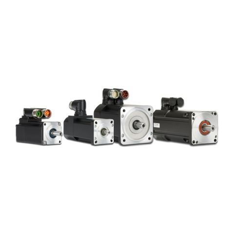
Servomotor series JHN, JHQ, and JL
User Manual
We automate your success.

This document has been compiled by Jetter AG with due diligence based on the state of the art as
known to them. Any revisions and technical advancements of our products are not automatically
made available in a revised document. Jetter AG shall not be liable for any errors either in form or
content, or for any missing updates, as well as for any damage or detriment resulting from such
failure.
Graeterstrasse 2
D-71642 Ludwigsburg | Germany
Phone:
Switchboard
+49 7141 2550-0
Sales
+49 7141 2550-531
Technical hotline
+49 7141 2550-444
E-mail:
Technical hotline
Sales
Translation of the original document
in German language
Item number
60884703
Document revision
6.10
Date of issue
December 2019
Jetter AG
www.jetter.de

Servomotor series JHN, JHQ, and JL – User Manual Table of contents
Jetter AG iii
Table of contents
1Introduction..........................................................................................................................10
1.1 Target groups ............................................................................................................. 10
1.2 Availability of information ............................................................................................ 10
1.3 Warranty information .................................................................................................. 10
1.4 Overview: Product-specific documentation related to Jetter AG motion systems ........ 11
1.5 Overview: General product documentation and tools.................................................. 12
1.6 Jetter AG in a nutshell................................................................................................. 13
The company ................................................................................................ 131.6.1
Jetter motors - Power in every size ............................................................... 131.6.2
1.7 Definitions of terms and calculation formulas .............................................................. 14
Definitions of terms ....................................................................................... 141.7.1
Formulas for spindle drive calculations.......................................................... 151.7.2
Formulas for rack-and-pinion drive or belt drive calculations ......................... 161.7.3
Legend..........................................................................................................171.7.4
2Safety advices...................................................................................................................... 18
2.1 General information ....................................................................................................18
2.2 Purpose ...................................................................................................................... 18
Intended use ................................................................................................. 182.2.1
Usage other than intended ............................................................................ 192.2.2
2.3Hazard levels.............................................................................................................. 19
2.4 Residual dangers........................................................................................................20
2.5 Instructions on EMC ...................................................................................................22
3Product description.............................................................................................................23
3.1 Motor series - Comparison.......................................................................................... 23
JHN series ....................................................................................................233.1.1
Servomotors of the JHQ series ..................................................................... 233.1.2
JL series ....................................................................................................... 243.1.3
3.2 Configurations ............................................................................................................ 24
Resolver........................................................................................................ 243.2.1
HIPERFACE®................................................................................................ 253.2.2
HIPERFACE DSL®........................................................................................ 253.2.3
Temperature sensor in the motor .................................................................. 253.2.4
Holding brake................................................................................................253.2.5
Gearings ....................................................................................................... 253.2.6
Further options.............................................................................................. 253.2.7
3.3 Scope of delivery ........................................................................................................26
3.4 Nameplate .................................................................................................................. 26
Nameplate of JHN and JL motors with UL Certification Mark ........................ 263.4.1
Nameplate of JL motors with UL and ATEX approval.................................... 273.4.2

Servomotor series JHN, JHQ, and JL – User Manual Table of contents
Jetter AG iv
Nameplate of JL1 motors .............................................................................. 283.4.3
Nameplate of JHQ motors with UL Certification Mark.................................... 283.4.4
Additional nameplate on JHQ motors with ATEX approval ............................ 293.4.5
Nameplate of JHQ22 motors with UL Certification Mark................................ 293.4.6
Model code number ...................................................................................... 303.4.7
Notes on operating the motors on safety controllers...................................... 323.4.8
Notes on operating the motors in potentially explosive areas ........................ 333.4.9
3.5 Hardware revision....................................................................................................... 34
3.6 Changing the outlet direction of the rotatable connector S-X....................................... 35
4General technical data ........................................................................................................37
4.1 Compatibility of the series........................................................................................... 37
4.2Flange sizes - Overview..............................................................................................37
4.3 Possible encoder/motor combinations (partly dependent on flange size) .................... 38
4.4 Resolver .....................................................................................................................38
4.5 Derating at ambient temperatures higher than 40 °C .................................................. 38
4.6 Design of the JHN and JL series................................................................................. 39
Standard configuration .................................................................................. 404.6.1
Derating at altitudes higher than 1000 m above sea level ............................. 404.6.2
4.7 Design of the JHQ series ............................................................................................40
Standard configuration .................................................................................. 404.7.1
Derating ........................................................................................................414.7.2
5Servomotors of the JHN series........................................................................................... 42
5.1 Flange size - JHN2 ..................................................................................................... 42
Technical data of the brake ........................................................................... 435.1.1
Specific technical data (DC link voltage DC 48 V) ......................................... 445.1.2
Torque/speed characteristic (DC link voltage DC 48 V)................................. 455.1.3
Specific technical data (DC link voltage DC 320 V) ....................................... 465.1.4
Torque/speed characteristic (DC link voltage DC 320 V)............................... 475.1.5
Specific technical data (DC link voltage DC 560 V) ....................................... 485.1.6
Torque/speed characteristic (DC link voltage DC 560 V)............................... 485.1.7
5.2 Flange size - JHN3 ..................................................................................................... 49
Technical data of the brake ........................................................................... 495.2.1
Specific technical data (DC link voltage DC 24 V/DC 48 V)........................... 505.2.2
Torque/speed characteristic (DC link voltage DC 24 V/DC 48 V) .................. 505.2.3
Specific technical data (DC link voltage DC 320 V) ....................................... 515.2.4
Torque/speed characteristic (DC link voltage DC 320 V)............................... 525.2.5
Specific technical data (DC link voltage DC 560 V) ....................................... 535.2.6
Torque/speed characteristic (DC link voltage DC 560 V)............................... 545.2.7
5.3 Flange size - JHN4 ..................................................................................................... 55
Technical data of the brake ........................................................................... 555.3.1
Specific technical data (DC link voltage DC 320 V) ....................................... 565.3.2

Servomotor series JHN, JHQ, and JL – User Manual Table of contents
Jetter AG v
Torque/speed characteristic (DC link voltage DC 320 V)............................... 575.3.3
Specific technical data (DC link voltage DC 560 V) ....................................... 585.3.4
Torque/speed characteristic (DC link voltage DC 560 V)............................... 595.3.5
5.4 Flange size - JHN5 ..................................................................................................... 60
Technical data of the brake ........................................................................... 605.4.1
Specific technical data (DC link voltage DC 320 V) ....................................... 615.4.2
Torque/speed characteristic (DC link voltage DC 320 V)............................... 615.4.3
Specific technical data (DC link voltage DC 560 V) ....................................... 625.4.4
Torque/speed characteristic (DC link voltage DC 560 V)............................... 635.4.5
5.5 Flange size - JHN6 ..................................................................................................... 64
Technical data of the brake ........................................................................... 645.5.1
Specific technical data (DC link voltage DC 560 V) ....................................... 655.5.2
Torque/speed characteristic (DC link voltage DC 560 V)............................... 675.5.3
5.6 Flange size - JHN7 ..................................................................................................... 68
Technical data of the brake ........................................................................... 685.6.1
Specific technical data (DC link voltage DC 560 V) ....................................... 695.6.2
Torque/speed characteristic (DC link voltage DC 560 V)............................... 705.6.3
6Servomotors of the JHQ series .......................................................................................... 71
6.1 Flange size - JHQ12 ...................................................................................................71
Technical data of the brake ........................................................................... 726.1.1
Specific technical data (DC link voltage DC 320 V) ....................................... 736.1.2
Torque/speed characteristic (DC link voltage DC 320 V)............................... 736.1.3
Specific technical data (DC link voltage DC 560 V) ....................................... 746.1.4
Torque/speed characteristic (DC link voltage DC 560 V)............................... 756.1.5
6.2 Flange size - JHQ2 ..................................................................................................... 76
Technical data of the brake ........................................................................... 776.2.1
Specific technical data (DC link voltage DC 24 V/DC 48 V)........................... 776.2.2
Torque/speed characteristic (DC link voltage DC 24 V/DC 48 V) .................. 786.2.3
Specific technical data (DC link voltage DC 320 V) ....................................... 796.2.4
Torque/speed characteristic (DC link voltage DC 320 V)............................... 846.2.5
Specific technical data (DC link voltage DC 560 V) ....................................... 866.2.6
Torque/speed characteristic (DC link voltage DC 560 V)............................... 906.2.7
6.3 Flange size - JHQ22 ...................................................................................................92
Technical data of the brake ........................................................................... 936.3.1
Specific technical data (DC link voltage DC 320 V) ....................................... 936.3.2
Torque/speed characteristic (DC link voltage DC 320 V)............................... 946.3.3
Specific technical data (DC link voltage DC 560 V) ....................................... 956.3.4
Torque/speed characteristic (DC link voltage DC 560 V)............................... 966.3.5
6.4 Flange size - JHQ23 ...................................................................................................97
Technical data of the brake ........................................................................... 986.4.1
Specific technical data (DC link voltage DC 320 V) ....................................... 986.4.2

Servomotor series JHN, JHQ, and JL – User Manual Table of contents
Jetter AG vi
Torque/speed characteristic (DC link voltage DC 320 V)............................. 1016.4.3
Specific technical data (DC link voltage DC 560 V) ..................................... 1026.4.4
Torque/speed characteristic (DC link voltage DC 560 V)............................. 1076.4.5
6.5 Flange size - JHQ24 ................................................................................................. 109
Technical data of the brake ......................................................................... 1106.5.1
Specific technical data (DC link voltage DC 320 V) ..................................... 1106.5.2
Torque/speed characteristic (DC link voltage DC 320 V)............................. 1126.5.3
Specific technical data (DC link voltage DC 560 V) ..................................... 1136.5.4
Torque/speed characteristic (DC link voltage DC 560 V)............................. 1156.5.5
6.6 Flange size - JHQ3 ................................................................................................... 116
Technical data of the brake ......................................................................... 1176.6.1
Specific technical data (DC link voltage DC 320 V) ..................................... 1176.6.2
Torque/speed characteristic (DC link voltage DC 320 V)............................. 1196.6.3
Specific technical data (DC link voltage DC 560 V) ..................................... 1206.6.4
Torque/speed characteristic (DC link voltage DC 560 V)............................. 1226.6.5
6.7 Flange size - JHQ4 ................................................................................................... 124
Technical data of the brake ......................................................................... 1256.7.1
Specific technical data (DC link voltage DC 320 V) ..................................... 1256.7.2
Torque/speed characteristic (DC link voltage DC 320 V)............................. 1266.7.3
Specific technical data (DC link voltage DC 560 V) ..................................... 1276.7.4
Torque/speed characteristic (DC link voltage DC 560 V)............................. 1296.7.5
6.8 Flange size - JHQ45 ................................................................................................. 131
Technical data of the brake ......................................................................... 1326.8.1
Specific technical data (DC link voltage DC 560 V) ..................................... 1326.8.2
Torque/speed characteristic (DC link voltage DC 560 V)............................. 1356.8.3
6.9 Flange size - JHQ5 ................................................................................................... 137
Technical data of the brake ......................................................................... 1386.9.1
Specific technical data (DC link voltage DC 320 V) ..................................... 1386.9.2
Torque/speed characteristic (DC link voltage DC 320 V)............................. 1396.9.3
Specific technical data (DC link voltage DC 560 V) ..................................... 1406.9.4
Torque/speed characteristic (DC link voltage DC 560 V)............................. 1436.9.5
6.10 Flange size - JHQ51 ................................................................................................. 146
Technical data of the brake ......................................................................... 1476.10.1
Specific technical data (DC link voltage DC 560 V) ..................................... 1476.10.2
Torque/speed characteristic (DC link voltage DC 560 V)............................. 1486.10.3
6.11 Flange size JHQ6/JHQ7 ........................................................................................... 149
Technical data of the brake ......................................................................... 1506.11.1
JHQ6 - Specific technical data (DC link voltage DC 560 V) ......................... 1506.11.2
JHQ6 - Torque/speed characteristic (DC link voltage DC 560 V)................. 1516.11.3
JHQ7 - Specific technical data (DC link voltage DC 560 V) ......................... 1526.11.4
JHQ7 - Torque/speed characteristic (DC link voltage DC 560 V)................. 1536.11.5

Servomotor series JHN, JHQ, and JL – User Manual Table of contents
Jetter AG vii
6.12 Flange size - JHQ71 ................................................................................................. 154
Technical data of the brake ......................................................................... 1556.12.1
Specific technical data (DC link voltage DC 560 V) ..................................... 1556.12.2
Torque/speed characteristic (DC link voltage DC 560 V)............................. 1566.12.3
6.13 Flange size - JHQ8 ................................................................................................... 157
Technical data of the brake ......................................................................... 1586.13.1
Specific technical data (DC link voltage DC 560 V) ..................................... 1586.13.2
Torque/speed characteristic (DC link voltage DC 560 V)............................. 1616.13.3
7Servomotors of the JL series............................................................................................ 163
7.1 Flange size - JL1 ...................................................................................................... 163
Technical data of the brake ......................................................................... 1657.1.1
Specific technical data (DC link voltage DC 24 V) ....................................... 1667.1.2
Torque/speed characteristic (DC link voltage DC 24 V)............................... 1667.1.3
Specific technical data (DC link voltage DC 48 V) ....................................... 1677.1.4
Torque/speed characteristic (DC link voltage DC 48 V)............................... 1677.1.5
Specific technical data (DC link voltage DC 320 V) ..................................... 1687.1.6
Torque/speed characteristic (DC link voltage DC 320 V)............................. 1697.1.7
7.2 Flange size - JL2 ...................................................................................................... 170
Technical data of the brake ......................................................................... 1707.2.1
Specific technical data (DC link voltage DC 70 V) ....................................... 1717.2.2
Torque/speed characteristic (DC link voltage DC 70 V)............................... 1717.2.3
Specific technical data (DC link voltage DC 320 V) ..................................... 1727.2.4
Torque/speed characteristic (DC link voltage DC 320 V)............................. 1747.2.5
Specific technical data (DC link voltage DC 560 V) ..................................... 1757.2.6
Torque/speed characteristic (DC link voltage DC 560 V)............................. 1757.2.7
7.3 Flange size - JL3 ...................................................................................................... 176
Technical data of the brake ......................................................................... 1767.3.1
Specific technical data (DC link voltage DC 320 V) ..................................... 1777.3.2
Torque/speed characteristic (DC link voltage DC 320 V)............................. 1797.3.3
Specific technical data (DC link voltage DC 560 V) ..................................... 1807.3.4
Torque/speed characteristic (DC link voltage DC 560 V)............................. 1817.3.5
7.4 Flange size - JL4 ...................................................................................................... 182
Technical data of the brake ......................................................................... 1827.4.1
Specific technical data (DC link voltage DC 320 V) ..................................... 1837.4.2
Torque/speed characteristic (DC link voltage DC 320 V)............................. 1847.4.3
Specific technical data (DC link voltage DC 560 V) ..................................... 1857.4.4
Torque/speed characteristic (DC link voltage DC 560 V)............................. 1867.4.5
7.5 Flange size - JL5 ...................................................................................................... 187
Technical data of the brake ......................................................................... 1877.5.1
Specific technical data (DC link voltage DC 320 V) ..................................... 1887.5.2
Torque/speed characteristic (DC link voltage DC 320 V)............................. 1897.5.3

Servomotor series JHN, JHQ, and JL – User Manual Table of contents
Jetter AG viii
Specific technical data (DC link voltage DC 560 V) ..................................... 1907.5.4
Torque/speed characteristic (DC link voltage DC 560 V)............................. 1917.5.5
7.6 Flange size - JL6 ...................................................................................................... 192
Technical data of the brake ......................................................................... 1927.6.1
Specific technical data (DC link voltage DC 320 V) ..................................... 1937.6.2
Torque/speed characteristic (DC link voltage DC 320 V)............................. 1947.6.3
Specific technical data (DC link voltage DC 560 V) ..................................... 1957.6.4
Torque/speed characteristic (DC link voltage DC 560 V)............................. 1967.6.5
7.7 Flange size - JL7 ...................................................................................................... 197
Technical data of the brake ......................................................................... 1977.7.1
Specific technical data (DC link voltage DC 320 V) ..................................... 1987.7.2
Torque/speed characteristic (DC link voltage DC 320 V)............................. 1987.7.3
Specific technical data (DC link voltage DC 560 V) ..................................... 1997.7.4
Torque/speed characteristic (DC link voltage DC 560 V)............................. 1997.7.5
7.8 Flange size - JL8 ...................................................................................................... 200
Technical data of the brake ......................................................................... 2007.8.1
Specific technical data (DC link voltage DC 560 V) ..................................... 2017.8.2
Torque/speed characteristic (DC link voltage DC 560 V)............................. 2027.8.3
8Installation and commissioning ....................................................................................... 203
8.1 Place of installation, ambient conditions ................................................................... 203
Check the servo motor before installation ................................................... 2038.1.1
Unsuitable places of installation - Shortening of service life ........................ 2038.1.2
Motor as ignition source in potentially explosive atmosphere ...................... 2038.1.3
Caution when assuming the wrong degree of protection ............................. 2048.1.4
Suitable place of installation........................................................................ 2048.1.5
8.2 Mechanical installation.............................................................................................. 204
Installation location...................................................................................... 2048.2.1
Mechanical equipment, tools....................................................................... 2048.2.2
Clutch, timing belts, timing belt pulleys, radial and axial load ...................... 2058.2.3
Cooling plate ............................................................................................... 2058.2.4
Carrying out the mechanical installation ...................................................... 2058.2.5
8.3 Electrical Installation - Hazards................................................................................. 207
Heat build-up of the motor during operation - Temperature monitoring........ 2078.3.1
Heat build-up of the motor during operation - Heat dissipation .................... 2088.3.2
Danger due to high operating voltage.......................................................... 2088.3.3
Danger from electrical leakage and stray currents....................................... 2088.3.4
8.4 Connections – New terminology, important notes on motor connections and wiring . 209
8.5 Electrical installation - Wiring description for 2-cable technology .............................. 210
JL1 motor, variant 1 (electrical connection S3-x.xx) .................................... 2108.5.1
JL1 motor, variant 2 (electrical connection S4-x.xx) .................................... 2118.5.2
JL1 motor, variant 3 (electrical connection SA-X) ........................................ 2138.5.3

Servomotor series JHN, JHQ, and JL – User Manual Table of contents
Jetter AG ix
Motors JHQ12, JHQ22 or JHQ24 (electrical connection SA-X or SB-X) ...... 2148.5.4
All other motors........................................................................................... 2158.5.5
8.6 Electrical installation - Wiring description for 1-cable technology .............................. 216
JHQ12, JHQ22 and JHQ24 motors ............................................................. 2178.6.1
All other motors........................................................................................... 2178.6.2
8.7 Commissioning ......................................................................................................... 218
Before starting work .................................................................................... 2188.7.1
Prerequisites for successful commissioning ................................................ 2198.7.2
During Commissioning ................................................................................ 2198.7.3
At the end of commissioning ....................................................................... 2208.7.4
Malfunctions and troubleshooting................................................................ 2218.7.5
9Maintenance and repairs................................................................................................... 223
9.1 Maintenance ............................................................................................................. 223
9.2 Repairs ..................................................................................................................... 224
9.3 Storage and shipment............................................................................................... 224
9.4 Disposal of obsolete equipment ................................................................................ 225
10 Service................................................................................................................................ 226
10.1 Customer service...................................................................................................... 226
11 Spare parts and accessories ............................................................................................ 227
11.1 Jetter servo cables.................................................................................................... 227
11.2 Connector ................................................................................................................. 227
11.3 Servomotors with mounted gearboxes...................................................................... 227

Servomotor series JHN, JHQ, and JL – User Manual Introduction
Jetter AG 10
1 Introduction
This document is part of the product documentation describing Jetter drive technology and must be
read and understood before using the motor. It contains important and safety-related information
for the proper use of the motor as intended. It also contains technical data and type designations
for synchronous servo motors by Jetter AG.
1.1 Target groups
This document is intended for specialists with appropriate qualifications.
The device may only be installed and commissioned by trained and qualified personnel who will
observe the standards DIN EN 50110-1 and DIN IEC 60364 in their work.
During the whole product life cycle, safe handling and operation of the device must be ensured. In
the case of missing or inadequate technical knowledge or knowledge of this document any liability
is excluded.
1.2 Availability of information
Make sure this document is kept at the ready in the vicinity of the product throughout its service
life.
For information on new revisions of this document, visit the download area on our website.
Start | Jetter - We automate your success.
This document is not subject to any updating service.
An overview of product documentation related to Jetter drive technology and where to find it is
described in chapters 1.4 Overview: Product-specific documentation related to Jetter AG motion
systems .
An overview of cross-product documentation and tools is described in chapters 1.5 Overview:
General product documentation and tools .
1.3 Warranty information
Your product has left our factory fully tested and ready to use.
The information on the nameplate applies to rated operating conditions.
Warranty claims only apply to Jetter AG products.
Any warranty claims for a complete system in combination with third-party products are excluded.
Repairs shall only be carried out by the manufacturer.
Warranty claims become void if the device is opened or if modifications are made.

Servomotor series JHN, JHQ, and JL – User Manual Introduction
Jetter AG 11
The following actions will void the warranty:
Dismantling or opening of gearbox, motor or encoder electronics.
Incorrect connection of the drive shaft which results in excessive forces acting on the
bearing of the drive shaft.
Impact or blows to motor, gearbox or encoder.
Mechanical work on the shaft, flange, plug or encoder housing.
1.4 Overview: Product-specific documentation related to Jetter AG
motion systems
Jetter motors and drives
Document category
Content
Format
Storage location
1 User manual Engineering/selection of
the servo motor,
installation and
commissioning
*.pdf On the Jetter homepage:
Downloads - Drives -
Servomotors
2 CAD- drawings for motors *.pdf, *.dxf
and *.stp
On the Jetter homepage:
Downloads - Drives -
Servomotors
3
Installation manual
Installation and
commissioning of
motors
*.pdf
On the Jetter homepage:
Downloads - Drives -
Servomotors
4 Gearing catalogs Selecting planetary gear
boxes, mounting on
Jetter motors, servicing
of gearboxes, etc.
*.pdf To be obtained from Jetter AG
on request
5
CAD-drawings and
datasheets for gearings
*.pdf, *.dxf
and *.stp
To be obtained from Jetter AG
on request
6 Catalog "Industrial
Automation"
Products and Services *.pdf On the Jetter homepage:
Downloads
JetMove
Document category
Content
Format
Storage location
1
User and installation
manuals of the respective
JetMove
Engineering/selection of
the servo amplifier,
dimensions, technical
data, ...
*.pdf
In hard-copy or for download
from the Jetter homepage or
on CD
(Documentation Set -
JM-1000/3000)
2 CAD-drawings and
datasheets, if needed
*.pdf, *.dxf
and *.stp
On the Jetter homepage for
download or on CD
(Documentation Set -
JM-1000/3000)

Servomotor series JHN, JHQ, and JL – User Manual Introduction
Jetter AG 12
JetControl - Safety, JX4 Interface
Document category
Content
Format
Storage location
1
User and installation
manuals on motion
controllers JC-440MC and
JC-945MC, as well as on
Safety controllers JSC-
110, JSC-210, JSC-220
and JSC-240
Engineering/selecting a
controller which is
equipped with the
corresponding X4
interface for connecting
JetMove devices
*.pdf In hard-copy or for download
from the Jetter homepage or
on CD
(Documentation Set -
JM-1000/3000)
2 CAD-drawings and
datasheets, if needed
*.pdf, *.dxf
and *.stp
On the Jetter AG homepage
for download
1.5 Overview: General product documentation and tools
Hardware
Document category
Content
Format
Storage location
1
Application Note 016 for
control cabinet
manufacturing and
installation
EMC-compliant
installation of servo
amplifiers and other
components, wiring and
shielding in the control
cabinet
*.pdf
On the Jetter homepage:
Downloads – Product-
independent documentation –
Application Notes
2
User manuals Peripherals *.pdf On the Jetter AG homepage
for download
Engineering and commissioning tools
Description
Content
Format
Storage location
1 JetSym software Jetter AG programming
and commissioning tool
For download from the Jetter
homepage or on product-
specific CD, licensing key
included
2
Motor database in JetSym
Characteristic curves
and electrical data of all
Jetter motors
*.pdf
JetSym programming software
3
Sizing tool SERVOsoft®
Engineering and
selecting Jetter motors,
gearboxes, servo
amplifiers and further
accessories
A license can be obtained
from SERVOsoft®or ordered
via Jetter AG
4
Sizing tool NCP for
Neugart gear units
Selecting a Neugart
planetary gear unit and
connecting it with a
Jetter motor
Free software download from
the Neugart homepage
5
JetSym online help
Information on error
messages and status
display
*.html

Servomotor series JHN, JHQ, and JL – User Manual Introduction
Jetter AG 13
1.6 Jetter AG in a nutshell
The company1.6.1
Jetter AG has been a competent industrial automation provider for more than 30 years. A
distinctive feature of Jetter technology is the integration of all automation functions into one system
and one programming language. This means that you will not need additional third party software
or hardware. Instead, you can meet any of your automation requirements by Jetter AG technology.
This holistic approach eliminates cumbersome software and hardware interfaces to give you an
integrated, optimally coordinated system. The result is simplified programming which grants earlier
commissioning of your systems. That will surely boost time-to-market! As early as in the nineties,
Jetter AG was the first enterprise in electronics industry vertical to consequently rely on networking
by standard Ethernet TCP/IP and by using Web technology (at Jetter AG, this is JetWeb
technology).
This made merging corporate IT network and production IT possible for the first time.
Subsequently, processes could be simplified, while forward-looking features such as remote
maintenance, could be implemented. Since the introduction of JetWeb technology thousands of
Jetter AG control solutions have been implemented in a wide range of applications in mechanical
and plant engineering - an expertise which now gives our customers the benefit of perfected
products and first-class service. Spurred by multiple success, Jetter AG keeps searching for, and
developing, new solutions and technologies to make automation still easier for you. Introducing a
new, even more powerful controller series, has been another milestone for Jetter AG proving it to
be a both competent and innovative partner in automation technology.
Jetter motors - Power in every size1.6.2
The correct choice and design of a servo motor is key to optimal drive and machine performance.
The long-term experience and the large product portfolio of Jetter AG help you find the motor most
fit for your specific application. Going with the JetMove servo amplifiers are Jetter motors featuring
DC link voltages of DC 24 to 560 V and a great selection of motor windings. The right combination
will produce the optimal speed for the application while also optimizing use of the servo amplifier's
rated current. All Jetter AG servo motors are extremely rugged 3-phase synchronous motors with
UL certification, which are available in the series JHN, JHQ, and JL.
A specific feature of JHN and JHQ motors is their automated segmented winding
technology and further optimized motor design, which result in high power density at very
low space requirements.
JHN motors are available in flange sizes 2 to 7 from 0.28 Nm to 60 Nm (flange 2 = 6-pole,
flange 3 or larger = 10-pole).
The JHQ motor series has the largest selection of flanges and encoders. From flange size
12 to 8, a torque range from 0.18 Nm to 120 Nm is supplied in 6-, 8- or 10-pole versions.
JL in classical winding technology are 6-pole motors and cover the range from 0.1 Nm
(JL1) to 115 Nm (JL8).
A large number of options for connector models, degree of protection or encoder design round off
the range and leave nothing to be desired when looking for a suitable servo motor. In addition to
the extensive range of motors, Jetter AG also offers pre-assembled and tested servo cables, as
well as ready installed suitable gear boxes. This saves you time and guarantees you a safe
system!

Servomotor series JHN, JHQ, and JL – User Manual Introduction
Jetter AG 14
1.7 Definitions of terms and calculation formulas
Definitions of terms1.7.1
Continuous stall torque
Mo[Nm]
Thermal limit torque that can be output for any length of time at standstill of the
motor and under rated ambient conditions.
Rated torque M
n
[Nm]
When the motor is drawing its rated current at its rated speed of n
n
, the rated
torque can be delivered for an unlimited period of time in S1 operating mode.
Continuous stall current Io
[A]
Required rms current for the development of the standstill torque Mo. The value
refers to the sinusoidal rms current.
Continuous rated current
In[A]
At a rated speed n
n
and at output of the rated torque, the motor will draw the
continuous rated current. This parameter refers to the sine-effective current
value.
Peak current Imax [A] Permitted peak current for 5 s max.! The peak current should not exceed 3.5
times the value of the continuous rated current.
Torque constant K
T
[Nm/A]
This constant specifies the amount of torque [Nm] that is output by the motor at
an RMS current of 1 A (M = I * KT).
Back EMF constant
KE[V/1000 RPM]
This constant specifies the induced electro-magnetic force of the motor related
to 1000 RPM as an RMS value between two motor phases.
Mass moment of inertia
JM[kgcm2]
The mass moment of inertia is given only for the rotor with standard equipment,
i.e. resolver feedback. Internal or external accessories (holding brake, encoder,
clutch) or a load may affect the values specified in this manual. Therefore, for
calculating the dynamic motor situation the mass moment of inertia has to be
taken into account in its entirety.
Axial load F
A
[N]
Rated axial load of the bare shaft end at the given speed and a ball bearing
service life of 20,000 hours.
Radial load F
R
[N]
Rated radial load of the bare shaft end at the given mean speed and a ball
bearing service life of 20,000 hours. The point where the radial load acts is in
the center of the shaft end.

Servomotor series JHN, JHQ, and JL – User Manual Introduction
Jetter AG 15
Formulas for spindle drive calculations1.7.2
Schematic of a spindle drive:
Formulas
Engine RPM
[RPM]
Load torque
[Nm]
Translatory mass moment of inertia
[kg m
2
]
Rotatory mass moment of inertia
[kg m2]
To steel the following formula applies:
[kg m2]
To aluminum the following formula applies:
[kg m2]
Sum of reduced mass moments of inertia
[kg m2]
Acceleration or deceleration torque MB= f(nM)
[Nm]
Acceleration or deceleration torque MB= f(sM)
[Nm]
Acceleration or deceleration time tB= f(nM)
[s]
Acceleration or deceleration time t
B
= f(sB)
[s]
Speed reached after acceleration
[RPM]
Acceleration or deceleration distance
[mm]
Output [W]
J
M
J
1
M
M
n
m
Spindelsteigung h
J
2
i = d
1
d2
ih106vn 4
m×××=
π×××= 000.2FihM
LL
( )( ) 6
2
102hmJ TT
−
×××= π
( ) ρId1032J
415
R
××××=
−
π
134
10Id7,7JR
−
×××=
134
10Id2,7JR
−
×××=
( )
TR1M
JJiJJ
J
2
+×
++=
B
MBmB t9,55Jnt60Jn2M ×
×=××××= π
M = (4 s J)/(h i t )BB
x x x xx
π B
i
2
BMB
MB M9,55J
nM60Jn
2
t×
×=×
××
×= π
( ) ( )
BBB
MihJs4t ×××××= π
BBM
tihs120n ×××=
120ihtns BMB ×××=
9,55nMP
MMA
×=

Servomotor series JHN, JHQ, and JL – User Manual Introduction
Jetter AG 16
Formulas for rack-and-pinion drive or belt drive calculations1.7.3
Schematic of a rack-and-pinion drive:
Formulas
Engine RPM
[RPM]
Load torque [Nm]
Translatory mass moment of inertia
[kg m2]
Rotatory mass moment of inertia
[kg m2]
To steel the following formula applies:
[kg m
2
]
To aluminum the following formula applies:
[kg m
2
]
Sum of reduced mass moments of inertia
[kg m2]
Acceleration or deceleration torque MB= f(nM)
[Nm]
Acceleration or deceleration torque MB= f(sM) [Nm]
Acceleration or deceleration time tB= f(nM)
[s]
Acceleration or deceleration time tB= f(sB) [s]
Speed reached after acceleration
[RPM]
Acceleration or deceleration distance
[mm]
Output
[W]
J
M
J
1
MM
nm
J
2
i =
d1
d2
id106vn
3
4
m
××××= π
000.2FidM
L3L
××=
( ) ρId1032J
415
R
××××=
−
π
134
10Id7,7JR
−
×××=
134
10Id2,7JR
−
×××=
( )
TR1M
JJiJJJ
2
+×++=
BMBmB t9,55Jnt60Jn2M ××=×××
×
= π
iM = (4 s J)/(d i t )B B 3Bx x xx
2
BMBMB M9,55JnM60Jn2t ××=××××= π
( ) ( )
B3BB
Mid
J
s4t ××××=
B3BM
tids120n ××××= π
120idtns
3BMB
××××= π
9,55nMP
MMA
×=

Servomotor series JHN, JHQ, and JL – User Manual Introduction
Jetter AG 17
Legend1.7.4
Legend for the formulas for calculating the spindle, rack-and-pinion or belt drive
d
=
Cylinder diameter [mm]
d1
=
Diameter of driving gear [mm]
d2
=
Diameter of driven gear [mm]
d3
=
Pinion or pulley diameter [mm]
FL
=
Feed force [N]
h
=
Spindle lead [mm]
i
=
Reduction ratio
l
=
Cylinder length [mm]
m
=
Cylinder weight [kg]
mT
=
Weight of linearly moved parts [kg]
MB
=
Acceleration, resp. deceleration torque [Nm]
MD
=
Continuous torque [Nm]
MI
=
Peak torque [Nm]
ML
=
Load torque [Nm]
MM
=
Motor torque [Nm]
MR
=
Friction torque [Nm]
nM
=
Motor speed [RPM]
PA
=
Output [W]
J
=
Mass moment of inertia [kg m2]
JM
=
Motor mass moment of inertia [kg m2]
JR
=
Rotatory mass moment of inertia [kg m2]
JT
=
Translatory mass moment of inertia [kg m2]
sB
=
Acceleration, resp. deceleration distance [mm]
tB
=
Acceleration, resp. deceleration time [s]
v
=
Feed rate [m/s]
h
=
Mechanical efficiency related to motor shaft
ρ
=
Density [kg/m3]
All motor calculations should be carried out on the basis of the most severe operating conditions.

Servomotor series JHN, JHQ, and JL – User Manual Safety advices
Jetter AG 18
2 Safety advices
2.1 General information
At the time of placing on the market, this product corresponds to the current state of the art and
meets the recognized safety rules.
Besides this user manual, laws and regulations in the operator's country are relevant to the
operation of the product. The operator is responsible for complying with the directives mentioned
below:
Applicable legislation, rules, and regulations
Relevant accident prevention regulations
Accepted safety rules
EU directives and other country-specific regulations
2.2 Purpose
Intended use2.2.1
The servo motors are intended for industrial or commercial applications.
They comply with the relevant parts of the harmonized series of standards EN 60034. If in special
cases, that is when motors are used in non-industrial or non-commercial plants increased
requirements apply, these requirements must be complied with on the part of the plant.
Typical applications are robotics and handling, machine tools, packaging and food processing
machinery and similar machines.
The servomotors may only be operated within the operating and environmental conditions
specified in the documentation (installation altitude, degree of protection, temperature range,
electrical and mechanical data, etc.).
Before commissioning systems and machines in which the servomotors are installed, the system
or machine must conform to the Machinery Directive, Low Voltage Directive and EMC Directive.
The rated AC voltage of the servo motors is 170 V or 310 V. The winding isolation is rated at DC
750 V. During braking operation, for example, the DC link voltage of the servo amplifier, however,
can amount up to DC 850 V. Thus, servo motors are subject to the EC Low Voltage Directive.
Systems and machines with inverter-fed three-phase motors must meet the protection
requirements of the EMC directive. It is the responsibility of the system installer to carry out the
correct installation. Use only shielded signal and power lines. Observe the instructions of the
inverter manufacturer for EMC-compliant installation.
The servomotors may only be put into operation after the EMC-compliant installation of the overall
system.

Servomotor series JHN, JHQ, and JL – User Manual Safety advices
Jetter AG 19
Usage other than intended2.2.2
The use of the servo drives and motors outside the aforementioned areas of application or under
operating ranges and environmental conditions other than those described in the documentation is
considered improper operation.
The JL, JHN and JHQ servo motors are not to be regarded as safety-related parts as per
Machinery Directive 2006/42/EC. For this reason, they are not qualified for safety-relevant
applications and must, therefore, NOT be used to protect persons.
These servo motors must not be used in technical systems which to a high degree have to be fail-
safe. The following areas of application are not intended applications:
Aviation and aerospace
Machinery specially designed or used for nuclear applications the failure of which may
result in the emission of radioactivity.
Medical devices that come into direct contact with the human body.
Machines for transporting and lifting persons.
Special facilities for use at fairs and amusement parks.
Devices for domestic use
NOTICE
Destruction of the servomotor!
A servomotor is not intended for direct connection to the three-phase mains.
Direct connection to the mains will destroy it.
•Servomotors have explicitly been designed for being torque, speed,
and/or position controlled by specific servo amplifiers, such as the
JetMove series by Jetter AG.
2.3 Hazard levels
DANGER
High risk
Indicates an imminently hazardous situation which, if not avoided, will result
in death or serious injury.
WARNING
Medium risk
Indicates a potential hazardous situation which, if not avoided, could result in
death or serious injury.
CAUTION
Low risk
Indicates a hazardous situation which, if not avoided, could result in minor or
moderate injury.
NOTICE
Material damage
Indicates a situation which, if not avoided, could result in malfunctions or
material damage.

Servomotor series JHN, JHQ, and JL – User Manual Safety advices
Jetter AG 20
2.4 Residual dangers
Consider the residual dangers mentioned in this chapter when assessing the risks associated with
your machine.
DANGER
Hazard caused by high operating voltage!
Extremely hazardous voltages of up to DC 900 V may occur!
The high operating voltage may cause muscle cramps, burns,
unconsciousness, respiratory standstill, or death.
•Do not remove any cover plates and keep all control cabinet doors
closed during operation.
•Check that all live connections are protected against contact.
•Do not open the motor housing.
•While the motor is in operation, do not touch the following
terminals: Power supply, motor voltage and DC link voltage.
DANGER
Danger in potentially explosive atmospheres!
Do not disconnect any plugs during operation!
The drive can become an ignition source in potentially explosive areas if you
disconnect the control or power plugs of the drive during operation.
•Never pull the motor connector while the motor is energized.
•Do not disconnect any connectors on the servo amplifier and the control
unit while higher currents are flowing.
DANGER
Danger in potentially explosive atmospheres!
Motor power limitations!
The motor can become an ignition source in potentially explosive areas if the
following instructions are not followed during operation.
•Limit electrical disturbances and vibrations by fine-tuning the control
parameters.
•The maximum speed must never be exceeded.
•The RMS value for rated current must not exceed the specifications on
the nameplate.
•For a rated speed close to 0, the RMS value of the rated current
indicated on the nameplate must be halved.
DANGER
Danger for persons with pacemakers and implants!
Electromagnetic fields caused by the drive!
Electric, magnetic and electromagnetic fields pose a particular hazard to
people with pacemakers, implants or similar devices.
•You must not be in the immediate vicinity of the drive if you belong to
the above group of persons.
Other manuals for JHN Series
1
This manual suits for next models
27
Table of contents
Other Jetter Engine manuals
