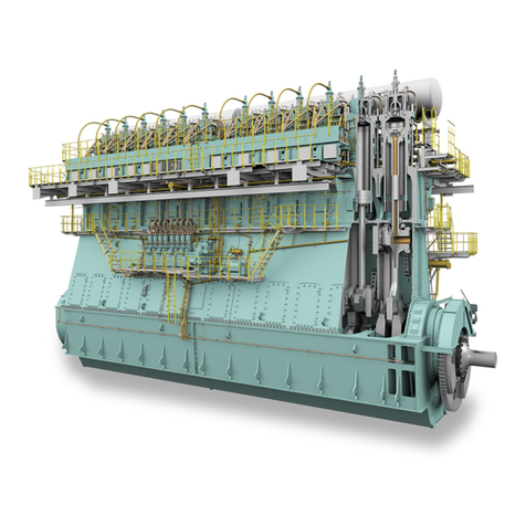
WinGD X72DF User manual

Maintenance Manual
X72DF
Issue 002 2020-10
Winterthur Gas & Diesel Ltd. Schützenstrasse 3 Tel. +41 (0)52 264 8844
Winterthur Gas & Diesel AG P.O. Box 414, 8401 Fax +41 (0)52 264 8866
Winterthur Gas & Diesel S.A. Winterthur, Switzerland www.wingd.com

© 2020 Winterthur Gas & Diesel Ltd. – All rights reserved
No part of this publication may be reproduced or copied in any form or by any means (electronic,
mechanical, graphic, photocopying, recording, taping or other information retrieval systems)
without the prior written permission of the copyright holder. Winterthur Gas & Diesel Ltd. makes
no representation, warranty (express or implied) in this publication and assumes no responsibility
for the correctness, errors or omissions of information contained herein. Information in this
publication is subject to change without notice.
NO LIABILITY, WHETHER DIRECT, INDIRECT, SPECIAL, INCIDENTAL OR CONSEQUENTIAL, IS
ASSUMED WITH RESPECT TO THE INFORMATION CONTAINED HEREIN. THIS PUBLICATION IS
INTENDED FOR INFORMATION PURPOSES ONLY.
www.wingd.com

Table of contents
1 Introduction
1.1 Maintenance Manual - change record........................................22
1.2 Preface..................................................................24
1.3 Technical documentation set................................................26
1.4 Data module codes (procedural data)........................................28
1.5 Data module codes (descriptive data)........................................30
1.6 Data module codes (illustrated parts data)....................................32
1.7 About this book...........................................................34
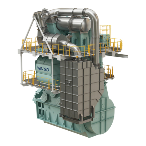
1.8 About the engine..........................................................36
1.9 List of abbreviations.......................................................42
2 Safety
2.1 Safety precautions and safety rules..........................................48
2.2 Safety precautions and safety rules for natural gas............................52
3 General data for maintenance
3.1 Lifting tools...............................................................56
3.2 Jointing compounds.......................................................60
3.3 Clearances - general......................................................62
3.4 Clearances...............................................................64
3.5 Torque values - standard screws............................................82
4 General mainteance procedures
4.1 Do maintenance work - general procedure................................... 86
4.2 Tighten a round nut with a pre-tensioner..................................... 88
4.3 Loosen a round nut with a pre-tensioner..................................... 92
4.4 Do a check of the pre-tension...............................................96
5 Maintenance schedule
5.1 Maintenance schedule....................................................100
6 Group 1 - Engine frame and bearings
6.1 Bedplate
6.1.1 Bedplate - do a check of the foundation bolts............................102
6.2 Main bearing
6.2.1 Main bearing - remove the cover...................................... 104
6.2.2 Main bearing - install the cover........................................110
6.3 Main bearing shell
6.3.1 Main bearing shell - remove...........................................116
X72DF
Maintenance Manual
Winterthur Gas & Diesel Ltd. - 3 - Issue 002 2020-10

6.3.2 Main bearing shell - examine..........................................122
6.3.3 Main bearing shell - install............................................124
6.4 Thrust bearing
6.4.1 Thrust bearing - examine the housing..................................132
6.4.2 Thrust bearing - do a check of the axial clearance with a dial gauge........134
6.4.3 Thrust bearing - do a check of the axial clearance with a inside micrometer. 136
6.4.4 Thrust bearing - remove the pads......................................140
6.4.5 Thrust bearing - install the pads....................................... 146
6.5 Engine stays
6.5.1 Engine stays (friction shims) - do a check of the pre-tension...............152
6.5.2 Engine stays (hydraulic) - do a check of the oil pressure..................154
6.6 Tie rod
6.6.1 Tie rod - do a check of the pre-tension..................................156
6.6.2 Tie rod - remove.....................................................158
6.6.3 Tie rod - install...................................................... 160
7 Group 2 - Cylinder
7.1 Cylinder liner
7.1.1 Cylinder liner - do a check of the bore..................................166
7.1.2 Cylinder liner - remove...............................................172
7.1.3 Cylinder liner - preserve..............................................178
7.1.4 Cylinder liner - grind................................................. 182
7.1.5 Cylinder liner - grind the lubricating groove..............................184
7.1.6 Cylinder liner - grind the scavenge ports................................186
7.1.7 Cylinder liner - install.................................................188
7.2 Lubricating quill
7.2.1 Lubricating quill - remove.............................................194
7.2.2 Lubricating quill - do a functional test...................................196
7.2.3 Lubricating quill - install.............................................. 198
7.3 Gas admission valve
7.3.1 Gas admission valve - do a check of the oil leakage flow..................202
7.3.2 Gas admission valve - remove........................................ 206
7.3.3 Gas admission valve - do a check for gas leakage.......................210
7.3.4 Gas admission valve - disassemble....................................214
7.3.5 Gas admission valve - assemble...................................... 218
7.3.6 Gas admission valve - install..........................................220
7.4 Piston rod gland
7.4.1 Piston rod gland - remove............................................ 224
7.4.2 Piston rod gland - do a check of the wear...............................228
7.4.3 Piston rod gland - install..............................................230
7.5 Cylinder cover
7.5.1 Cylinder cover - remove..............................................234
7.5.2 Cylinder cover - grind the sealing face for injection valve..................240
X72DF
Maintenance Manual
Winterthur Gas & Diesel Ltd. - 4 - Issue 002 2020-10

7.5.3 Cylinder cover - grind the sealing face for pilot injection valve............. 244
7.5.4 Cylinder cover - grind the sealing face for prechamber....................248
7.5.5 Cylinder cover - install................................................252
7.6 Direct controlled injection valve
7.6.1 Direct controlled injection valve - remove............................... 258
7.6.2 Direct controlled injection valve - do a functional test.....................260
7.6.3 Direct controlled injection valve - disassemble...........................264
7.6.4 Direct controlled injection valve - assemble............................. 268
7.6.5 Direct controlled injection valve - install.................................270
7.7 Starting air valve
7.7.1 Starting air valve - remove the solenoid valve........................... 272
7.7.2 Starting air valve - remove............................................274
7.7.3 Starting air valve - disassemble....................................... 278
7.7.4 Starting air valve - grind..............................................280
7.7.5 Starting air valve - assemble..........................................282
7.7.6 Starting air valve - install............................................. 284
7.7.7 Starting air valve - install the solenoid valve.............................286
7.8 Relief valve combustion chamber
7.8.1 Relief valve combustion chamber - remove............................. 288
7.8.2 Relief valve combustion chamber - install...............................290
7.9 Exhaust valve
7.9.1 Exhaust valve - remove.............................................. 292
7.9.2 Exhaust valve - disassemble..........................................296
7.9.3 Exhaust valve - remove the seat (with new tool)......................... 300
7.9.4 Exhaust valve - do a check of the seat................................. 304
7.9.5 Exhaust valve - grind the seat.........................................308
7.9.6 Exhaust valve - install the seat (with new tool)...........................310
7.9.7 Exhaust valve - assemble............................................ 314
7.9.8 Exhaust valve - install................................................322
7.10 Pilot injection valve
7.10.1 Pilot injection valve - remove..........................................326
7.10.2 Pilot injection valve - remove the injection module....................... 330
7.10.3 Pilot injection valve - install the injection module.........................332
7.10.4 Pilot injection valve - do a functional test................................336
7.10.5 Pilot injection valve - remove the pre-chamber...........................340
7.10.6 Pilot injection valve - install the pre-chamber............................342
7.10.7 Pilot injection valve - install........................................... 344
8 Group 3 - Crankshaft, connecting rod and piston
8.1 Crankshaft
8.1.1 Crankshaft - do a check of the crank deflection..........................350
8.1.2 Crankshaft - install the work platform...................................356
8.1.3 Crankshaft - remove the work platform................................. 358
X72DF
Maintenance Manual
Winterthur Gas & Diesel Ltd. - 5 - Issue 002 2020-10

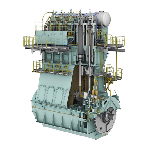
8.2 Torsional vibration damper
8.2.1 Torsional vibration damper - examine.................................. 360
8.3 Axial vibration damper
8.3.1 Axial vibration damper - disassemble...................................362
8.3.2 Axial vibration damper - assemble.....................................366
8.4 Turning gear
8.4.1 Turning gear - do a check of the screwed connections....................372
8.4.2 Turning gear - lubricate the teeth...................................... 374
8.5 Connecting rod
8.5.1 Connecting rod - prepare before removal...............................378
8.5.2 Connecting rod - remove............................................. 382
8.5.3 Connecting rod - remove the top end bearing cover......................392
8.5.4 Connecting rod - remove the top end bearing........................... 398
8.5.5 Connecting rod - remove the bottom end bearing........................400
8.5.6 Connecting rod - examine the bearing shells............................408
8.5.7 Connecting rod - install the bottom end bearing..........................410
8.5.8 Connecting rod - install the top end bearing.............................420
8.5.9 Connecting rod - install the top end bearing cover........................426
8.5.10 Connecting rod - install...............................................432
8.6 Crosshead
8.6.1 Crosshead - remove.................................................444
8.6.2 Crosshead - do a check of the clearances.............................. 458
8.6.3 Crosshead - install...................................................462
8.7 Piston
8.7.1 Piston (installed) - do checks of the surface and clearances...............472
8.7.2 Piston - prepare before removal.......................................476
8.7.3 Piston - remove..................................................... 482
8.7.4 Piston - disassemble.................................................486
8.7.5 Piston (removed) - do checks of the surface and clearances.............. 490
8.7.6 Piston - assemble................................................... 494
8.7.7 Piston - install.......................................................498
8.8 Piston ring
8.8.1 Piston ring - remove................................................. 504
8.8.2 Piston ring - install...................................................506
9 Group 4 - Supply unit drive and control components
9.1 Driving wheel
9.1.1 Gear wheel crankshaft - examine the teeth..............................510
9.1.2 Gear wheel crankshaft - do a check of the teeth backlash.................512
9.2 Shut-off valve for starting air
9.2.1 Shut-off valve for starting air - disassemble............................. 516
9.2.2 Shut-off valve for starting air - assemble................................522
9.2.3 Shut-off valve for starting air - do a test of the operation.................. 526
X72DF
Maintenance Manual
Winterthur Gas & Diesel Ltd. - 6 - Issue 002 2020-10

10 Group 5 - Supply unit, pumps and control valves
10.1 Servo oil pump
10.1.1 Servo oil pump - do a check for wear and damage.......................530
10.1.2 Servo oil pump - remove............................................. 532
10.1.3 Servo oil pump - install...............................................536
10.2 Supply unit for pilot fuel
10.2.1 Supply unit for pilot fuel - remove the pump.............................540
10.2.2 Supply unit for pilot fuel - lubricate the coupling..........................544
10.2.3 Supply unit for pilot fuel - install the pump...............................546
10.3 Fuel pump
10.3.1 Fuel pump - remove................................................. 550
10.3.2 Fuel pump - disassemble.............................................554
10.3.3 Fuel pump - assemble............................................... 560
10.3.4 Fuel pump - install...................................................568
10.3.5 Fuel pump - do a test of the operation..................................572
10.4 Fuel pump actuator
10.4.1 Fuel pump actuator - calibrate.........................................576
10.4.2 Fuel pump actuator - adjust...........................................580
10.5 Fuel pressure control valve
10.5.1 Fuel rail - remove the pressure control valve............................ 584
10.5.2 Fuel rail - do a check of the pressure control valve.......................586
10.5.3 Fuel rail - install the pressure control valve..............................590
10.6 Fuel overpressure safety valve
10.6.1 Fuel rail - remove the overpressure safety valve.........................592
10.6.2 Fuel rail - do a check of the overpressure safety valve....................594
10.6.3 Fuel rail - install the overpressure safety valve...........................598
10.7 Flow limiting valve
10.7.1 Flow limiting valve - do an inspection...................................600
10.7.2 Flow limiting valve - remove...........................................604
10.7.3 Flow limiting valve - install............................................608
10.8 Exhaust valve control unit
10.8.1 Exhaust valve control unit (VCU) - remove..............................612
10.8.2 Exhaust valve control unit (VCU) - disassemble......................... 614
10.8.3 Exhaust valve control unit (VCU) - assemble............................616
10.8.4 Exhaust valve control unit (VCU) - install............................... 618
11 Group 6 - Scavenge air components
11.1 Scavenge air receiver
11.1.1 Scavenge air receiver - examine.......................................624
11.1.2 Scavenge air receiver - do a check of the relief valve.....................628
11.1.3 Scavenge air receiver - remove the flaps............................... 630
11.1.4 Scavenge air receiver - install the flaps.................................632
X72DF
Maintenance Manual
Winterthur Gas & Diesel Ltd. - 7 - Issue 002 2020-10

11.2 Auxiliary blower
11.2.1 Auxiliary blower - remove.............................................634
11.2.2 Auxiliary blower - install.............................................. 640
11.3 Scavenge air cooler
11.3.1 Scavenge air cooler - remove.........................................646
11.3.2 Scavenge air cooler - install...........................................654
11.4 Water separator
11.4.1 Water separator - remove.............................................658
11.4.2 Water separator - install..............................................664
12 Group 7 - Cylinder lubrication and balancer
12.1 Cylinder lubrication system
12.1.1 Cylinder lubrication system - do a functional test.........................670
12.1.2 Cylinder lubrication system - bleed.....................................672
12.1.3 Cylinder lubricating pump - remove.................................... 676
12.1.4 Cylinder lubricating pump (MK-1) - examine.............................680
12.1.5 Cylinder lubricating pump (MK-E) - do a service......................... 682
12.1.6 Cylinder lubricating pump - install......................................686
12.2 Integrated electric balancer (iELBA)
12.2.1 Integrated electric balancer - prepare before the bearings removal.........688
12.2.2 Integrated electric balancer - remove the bearing (engine side)............690
12.2.3 Integrated electric balancer - remove the bearing (outer side)............. 694
12.2.4 Integrated electric balancer - do a check of the bearing clearance..........698
12.2.5 Integrated electric balancer - adjust the bearings........................ 702
12.2.6 Electric balancer sensor unit - remove the proximity sensor............... 706
12.2.7 Electric balancer sensor unit - install the proximity sensor.................708
12.2.8 Integrated electric balancer - do a check of the backlash..................710
12.2.9 Integrated electric balancer - install the bearing (engine side)..............714
12.2.10 Integrated electric balancer - install the bearing (outer side)...............716
13 Group 8 - Pipes
13.1 HP servo oil pipe
13.1.1 HP servo oil pipe - remove............................................720
13.1.2 HP servo oil pipe - grind the sealing face............................... 724
13.1.3 HP servo oil pipe - install............................................. 728
13.2 Hydraulic pipe exhaust valve
13.2.1 Hydraulic pipe exhaust valve - remove................................. 732
13.2.2 Hydraulic pipe exhaust valve - grind the sealing face.....................736
13.2.3 Hydraulic pipe exhaust valve - install...................................740
13.3 HP fuel pipe
13.3.1 HP fuel pipe (fuel rail to injection valve) - prepare before removal..........744
13.3.2 HP fuel pipe (fuel rail to injection valve) - remove........................ 746
13.3.3 HP fuel pipe (fuel rail to injection valve) - grind the sealing face............748
X72DF
Maintenance Manual
Winterthur Gas & Diesel Ltd. - 8 - Issue 002 2020-10

13.3.4 HP fuel pipe (fuel rail to injection valve) - install..........................752
13.3.5 HP fuel pipe (fuel pump to fuel rail) - prepare before removal..............756
13.3.6 HP fuel pipe (fuel pump to fuel rail) - remove............................758
13.3.7 HP fuel pipe (fuel pump to fuel rail) - grind the sealing face................760
13.3.8 HP fuel pipe (fuel pump to fuel rail) - install..............................764
13.4 HP pilot fuel pipe
13.4.1 HP pilot fuel pipe - remove............................................768
13.4.2 HP pilot fuel pipe - install............................................. 772
14 Group 9 - Monitoring instruments
14.1 Crank angle sensor unit
14.1.1 Crank angle sensor unit (supply unit) - remove the proximity sensor........778
14.1.2 Crank angle sensor unit (supply unit) - install the proximity sensor......... 782
14.1.3 Crank angle sensor unit (flywheel) - remove the proximity sensor..........786
14.1.4 Crank angle sensor unit (flywheel) - install the proximity sensor............790
14.2 Selective catalytic reduction system (SCR)
14.2.1 SCR - remove the valve..............................................794
14.2.2 SCR - install the valve................................................796
14.3 Electronic components
14.3.1 Gas detector - calibrate.............................................. 798
14.3.2 LDU-20 - remove....................................................804
14.3.3 LDU-20 - install..................................................... 808
14.3.4 CCM-20 - remove................................................... 812
14.3.5 CCM-20 - install.....................................................814
14.3.6 MCM-11 - remove................................................... 816
14.3.7 MCM-11 - install.....................................................818
14.3.8 IOM-10 - remove....................................................820
14.3.9 IOM-10 - install......................................................822
15 Tools
15.1 General for tools.........................................................826
15.2 Standard tools...........................................................828
15.3 Recommended tools..................................................... 874
16 Tightening instructions
16.1 Tightening instructions....................................................880
17 Maintenance overview
17.1 Maintenance overview....................................................882
X72DF
Maintenance Manual
Winterthur Gas & Diesel Ltd. - 9 - Issue 002 2020-10

X72DF
Maintenance Manual
Page left intentionally blank
Winterthur Gas & Diesel Ltd. - 10 - Issue 002 2020-10

List of tables
1 Introduction
1-1 Change record ............................................................................................. 22
1-2 Data module codes (procedural data) ......................................................... 28
1-3 Data module codes (descriptive data) ......................................................... 30
1-4 Data module codes (illustrated parts data) .................................................. 32
1-5 List of abbreviations and acronyms ............................................................. 42
3 General data for maintenance
3-1 Lifting capacities (for information only) ........................................................ 57
3-2 Jointing compound ...................................................................................... 60
3-3 Crankshaft and thrust bearing - clearances ................................................ 64
3-4 Crankshaft and main bearings .................................................................... 66
3-5 Crosshead guide ......................................................................................... 67
3-6 Cylinder liner ............................................................................................... 68
3-7 Piston rod gland .......................................................................................... 69
3-8 Exhaust valve - spindle and guide bush ...................................................... 70
3-9 Connecting rod - top and bottom end bearings ........................................... 71
3-10 Piston and piston rings ................................................................................ 72
3-11 Supply unit - drive wheels ........................................................................... 75
3-12 Fuel and servo pump units .......................................................................... 77
3-13 Fuel pump ................................................................................................... 79
3-14 Integrated electric balancer ......................................................................... 81
3-15 Torque value - applicable decrease ............................................................. 82
3-16 Torque values - standard screws ................................................................. 83
7 Group 2 - Cylinder
7-1 GAV - usual values of oil leakage flow at 25°C ........................................... 204
7-2 Exhaust valve, clearance X ......................................................................... 305
7-3 Damper settings .......................................................................................... 318
8 Group 3 - Crankshaft, connecting rod and piston
8-1 Maximum permitted difference in mm ......................................................... 353
8-2 Crank-web deflection limits in mm ............................................................... 354
8-3 Recommended suppliers ............................................................................. 376
8-4 ISO VG 1000/1500 suppliers ....................................................................... 418
8-5 ISO VG 1000/1500 suppliers ....................................................................... 421
8-6 Torque values .............................................................................................. 495
10 Group 5 - Supply unit, pumps and control valves
10-1 Distance X for VCU ..................................................................................... 620
13 Group 8 - Pipes
X72DF
Maintenance Manual
Winterthur Gas & Diesel Ltd. - 11 - Issue 002 2020-10

13-1 Distance X for HP servo oil pipe .................................................................. 725
13-2 Distance X for hydraulic pipe exhaust valve ................................................ 741
13-3 Distances X and Y for HP fuel pipe ............................................................. 753
13-4 Distance X for HP fuel pipe ......................................................................... 765
13-5 Distance X for pilot fuel pipe ........................................................................ 773
X72DF
Maintenance Manual
Winterthur Gas & Diesel Ltd. - 12 - Issue 002 2020-10

List of illustrations
1 Introduction
1-1 Side view (generic) ...................................................................................... 37
1-2 End view (generic, seen from the driving end) ............................................ 38
1-3 Standard and LEFT engine (generic, seen from the driving end) ............... 39
1-4 Engine numbering (generic) ........................................................................ 40
3 General data for maintenance
3-1 RUD-eye bolts ............................................................................................. 58
3-2 RUD-swivel lugs .......................................................................................... 59
3-3 Crankshaft and Thrust Bearing ................................................................... 64
3-4 Crankshaft and main bearings .................................................................... 65
3-5 Crosshead Guide ........................................................................................ 67
3-6 Cylinder liner ............................................................................................... 68
3-7 Piston rod gland .......................................................................................... 69
3-8 Exhaust valve .............................................................................................. 70
3-9 Connecting rod - top and bottom end bearings ........................................... 71
3-10 Clearances - piston rings ............................................................................. 72
3-11 Supply unit - drive wheels ........................................................................... 74
3-12 Clearances - fuel and servo pump units ...................................................... 76
3-13 Fuel pump ................................................................................................... 78
3-14 Clearances - ELBA ...................................................................................... 80
4 General mainteance procedures
4-1 Tighten a round nut (examples) ................................................................... 89
4-2 Loosen a round nut (examples) ................................................................... 93
4-3 Do a check of the pre-tension (examples) ................................................... 97
6 Group 1 - Engine frame and bearings
6-1 Foundation bolts .......................................................................................... 103
6-2 Main bearing cover (example) ..................................................................... 105
6-3 Thrust device ............................................................................................... 106
6-4 Bearing cover .............................................................................................. 107
6-5 Bearing cover - move .................................................................................. 108
6-6 Thrust device ............................................................................................... 111
6-7 Bearing cover - install .................................................................................. 112
6-8 Bearing cover - move .................................................................................. 113
6-9 Bearing cover - oil pipe ................................................................................ 114
6-10 Crankshaft and flywheel - lift ....................................................................... 119
6-11 Bearing shell - remove ................................................................................ 120
6-12 Bearing shell - lift ......................................................................................... 121
6-13 Bearing shell - lift ......................................................................................... 127
6-14 Bearing shell - install ................................................................................... 129
6-15 Crankshaft and flywheel - lift ....................................................................... 130
X72DF
Maintenance Manual
Winterthur Gas & Diesel Ltd. - 13 - Issue 002 2020-10

6-16 Visual examination ...................................................................................... 133
6-17 Axial clearance ............................................................................................ 135
6-18 Axial clearance - micrometer ....................................................................... 137
6-19 Cover - remove ............................................................................................ 141
6-20 Thrust pad - removal ................................................................................... 143
6-21 Thrust pad - install ....................................................................................... 148
6-22 Thrust pads - configuration .......................................................................... 149
6-23 Cover - install .............................................................................................. 150
6-24 Engine stays - pressure check .................................................................... 155
6-25 Pre-tension checks ...................................................................................... 157
6-26 Tie rod - removal ......................................................................................... 159
6-27 Tie rod - install ............................................................................................. 161
6-28 Tie rod - apply tension ................................................................................. 162
7 Group 2 - Cylinder
7-1 Cylinder liner - dimension check ................................................................. 169
7-2 Water guide jacket ....................................................................................... 174
7-3 Lifting tool (example) ................................................................................... 175
7-4 Cylinder liner (example) - move .................................................................. 176
7-5 Cylinder liner - storage ................................................................................ 179
7-6 Cylinder liner - storage 2 ............................................................................. 180
7-7 Cylinder liner - grind .................................................................................... 183
7-8 Lubricating grooves - grind .......................................................................... 185
7-9 Scavenge ports - grind ................................................................................ 187
7-10 Insulation bandage ...................................................................................... 189
7-11 Cylinder liner (example) .............................................................................. 190
7-12 Water guide jacket (example) ...................................................................... 191
7-13 Lubricating quill (example) .......................................................................... 195
7-14 Lubricating quill ........................................................................................... 197
7-15 Sealing surface ............................................................................................ 199
7-16 Lubricating quill (example) .......................................................................... 200
7-17 GAV - do a check of the oil leakage flow ..................................................... 203
7-18 Compensator - remove ................................................................................ 207
7-19 Gas admission valve - remove .................................................................... 208
7-20 Gas admission valve - pressure check ........................................................ 211
7-21 Valve seat - lap ............................................................................................ 212
7-22 Valve spindle - remove ................................................................................ 216
7-23 GAV - assemble ........................................................................................... 219
7-24 Gas admission valve - install ....................................................................... 221
7-25 Electrical connection ................................................................................... 222
7-26 Compensator - install .................................................................................. 223
7-27 Piston rod gland - remove and install .......................................................... 225
7-28 Piston rod gland - disassemble ................................................................... 226
7-29 Piston rod gland (example) ......................................................................... 229
7-30 Piston rod gland - assemble ........................................................................ 232
7-31 Piston rod gland - remove and install .......................................................... 233
7-32 Cylinder cover - pipes and expansion piece (example) ............................... 236
7-33 Lifting tool - pre-tensioner (example) ........................................................... 237
X72DF
Maintenance Manual
Winterthur Gas & Diesel Ltd. - 14 - Issue 002 2020-10

7-34 Cylinder cover, exhaust valve cage and water guide jacket (example) ....... 238
7-35 Cylinder cover and exhaust valve cage (example) ...................................... 239
7-36 Fuel injection valve position - grind ............................................................. 242
7-37 Grind the sealing face for pilot injection valve ............................................. 246
7-38 Grind the sealing face for prechamber ........................................................ 249
7-39 Assemble before installation (example) ...................................................... 254
7-40 Lifting tool - pre-tensioner (example) ........................................................... 255
7-41 Direct controlled injection valve ................................................................... 259
7-42 Test bench (example) .................................................................................. 261
7-43 Direct controlled injection valve - disassemble ............................................ 265
7-44 Nozzle tip - remove ..................................................................................... 265
7-45 Direct controlled injection valve - assemble ................................................ 269
7-46 Direct controlled injection valve - install ...................................................... 271
7-47 Starting air valve (example) ......................................................................... 273
7-48 Starting air valve - preparation .................................................................... 275
7-49 Starting air valve - remove .......................................................................... 276
7-50 Starting air valve - disassemble .................................................................. 279
7-51 Starting air valve - grind .............................................................................. 281
7-52 Starting air valve - assemble ....................................................................... 283
7-53 Starting air valve - install ............................................................................. 285
7-54 Starting air valve (example) ......................................................................... 287
7-55 Relief valve combustion chamber ............................................................... 289
7-56 Relief valve combustion chamber ............................................................... 291
7-57 Exhaust valve - preparation ......................................................................... 293
7-58 Exhaust valve - removal .............................................................................. 294
7-59 Exhaust valve - disassemble ....................................................................... 298
7-60 Guide bush - removal .................................................................................. 299
7-61 Valve seat - remove ..................................................................................... 301
7-62 Valve seat clearance ................................................................................... 306
7-63 Valve seat - grinding tool ............................................................................. 309
7-64 Valve seat - install ........................................................................................ 312
7-65 Guide bush - installation .............................................................................. 315
7-66 Valve spindle - installation ........................................................................... 317
7-67 Damper setting (example) ........................................................................... 318
7-68 Valve stroke sensor, throttle and non-return valve ...................................... 319
7-69 Exhaust valve - installation .......................................................................... 323
7-70 Expansion piece - installation ...................................................................... 324
7-71 Exhaust valve - complete the installation .................................................... 325
7-72 Pilot injection valve ...................................................................................... 327
7-73 Pilot injection valve - remove ....................................................................... 328
7-74 Pilot fuel valve - remove the injection module ............................................. 331
7-75 Pilot fuel valve - install the injection module ................................................ 333
7-76 Pilot fuel valve - install the nozzle nut ......................................................... 334
7-77 Pilot injection valve - checks ....................................................................... 339
7-78 Pilot injection valve - remove the pre-chamber ........................................... 341
7-79 Pilot injection valve - install the pre-chamber .............................................. 343
7-80 Seal - install ................................................................................................. 345
7-81 Pilot injection valve - install ......................................................................... 346
X72DF
Maintenance Manual
Winterthur Gas & Diesel Ltd. - 15 - Issue 002 2020-10

7-82 Pilot injection valve ...................................................................................... 347
8 Group 3 - Crankshaft, connecting rod and piston
8-1 Dial gauge position ...................................................................................... 351
8-2 Crank positions for clockwise direction ....................................................... 352
8-3 Definitions of positions ................................................................................ 353
8-4 Definition of deflection ................................................................................. 355
8-5 Platforms ..................................................................................................... 357
8-6 Platforms ..................................................................................................... 359
8-7 Axial vibration damper - housing and pipes ................................................ 363
8-8 Axial vibration damper ................................................................................. 364
8-9 Axial vibration damper - move ..................................................................... 365
8-10 Axial vibration damper - install .................................................................... 368
8-11 Axial vibration damper - bolts ...................................................................... 369
8-12 Axial vibration damper - housing and pipes ................................................ 370
8-13 Turning gear - do a check ............................................................................ 373
8-14 Turning gear and gear wheels ..................................................................... 375
8-15 Pyroshield .................................................................................................... 376
8-16 Klüberfluid ................................................................................................... 376
8-17 Connecting rod ............................................................................................ 379
8-18 Stop plate .................................................................................................... 380
8-19 Connecting rod - move ................................................................................ 385
8-20 Connecting rod - remove ............................................................................. 387
8-21 Connecting rod - move 2 ............................................................................. 389
8-22 Preparation .................................................................................................. 394
8-23 Equipment - install ....................................................................................... 395
8-24 Top bearing cover - removal ........................................................................ 396
8-25 Top end bearing - remove ........................................................................... 399
8-26 Bottom end bearing cover - move ............................................................... 402
8-27 Bottom end bearing shell - remove ............................................................. 403
8-28 Supports ...................................................................................................... 404
8-29 Bottom end bearing ..................................................................................... 405
8-30 Top bearing shell - remove .......................................................................... 406
8-31 Visual examination ...................................................................................... 409
8-32 Top bearing shell - move ............................................................................. 413
8-33 Bottom end bearing ..................................................................................... 414
8-34 Supports ...................................................................................................... 415
8-35 Bottom end bearing - install ......................................................................... 417
8-36 Top end bearing - move ............................................................................... 422
8-37 Crosshead - lower ....................................................................................... 423
8-38 Bearing lubrication ....................................................................................... 424
8-39 Top bearing cover - move ............................................................................ 427
8-40 Top bearing cover - install ........................................................................... 429
8-41 Connecting rod - move 2 ............................................................................. 434
8-42 Connecting rod - install 1 ............................................................................. 436
8-43 Connecting rod - install 2 ............................................................................. 438
8-44 Crosshead - install ....................................................................................... 440
8-45 Toggle lever - attach .................................................................................... 441
X72DF
Maintenance Manual
Winterthur Gas & Diesel Ltd. - 16 - Issue 002 2020-10

8-46 Piston - attach ............................................................................................. 442
8-47 Toggle lever - remove .................................................................................. 446
8-48 Crosshead bearing - temperature sensor .................................................... 447
8-49 Tools - prepare ............................................................................................ 448
8-50 Bracket - attach ........................................................................................... 449
8-51 Tools - attach ............................................................................................... 450
8-52 Connecting rod - move ................................................................................ 451
8-53 Crosshead - move ....................................................................................... 452
8-54 Crosshead - remove .................................................................................... 453
8-55 Crosshead - remove .................................................................................... 455
8-56 Guide shoes - remove ................................................................................. 456
8-57 Clearance checks ........................................................................................ 459
8-58 Dimensions check ....................................................................................... 460
8-59 Guide shoe - move ...................................................................................... 464
8-60 Crosshead - move ....................................................................................... 465
8-61 Guide shoes - install .................................................................................... 466
8-62 Connecting rod - move ................................................................................ 468
8-63 Tools - remove ............................................................................................. 469
8-64 Toggle lever - attach .................................................................................... 470
8-65 Crosshead bearing - temperature sensor .................................................... 471
8-66 Top surface - dimensions check .................................................................. 473
8-67 Piston ring - clearance ................................................................................. 474
8-68 Piston - Preparation ..................................................................................... 477
8-69 Piston - Preparation before removal (example) ........................................... 479
8-70 Piston - remove (example) .......................................................................... 483
8-71 Piston - Preparation before disassembly ..................................................... 487
8-72 Piston - disassemble (example) .................................................................. 488
8-73 Top surface - dimensions check .................................................................. 491
8-74 Piston groove clearance - calliper gauge .................................................... 491
8-75 Piston - assemble (example) ....................................................................... 496
8-76 Piston - move (example) ............................................................................. 499
8-77 Piston - install (example) ............................................................................. 500
8-78 Piston rod gland - attach (example) ............................................................ 501
8-79 Piston - attach (example) ............................................................................ 502
8-80 Piston ring - remove (example) ................................................................... 505
8-81 Piston rings - install (example) .................................................................... 507
9 Group 4 - Supply unit drive and control
components
9-1 Driving wheel - gear tooth backlash ............................................................ 514
9-2 Shut-off valve for starting air - prepare for disassembly .............................. 517
9-3 Shut-off valve for starting air - disassemble ................................................ 519
9-4 Shut-off valve for starting air - assemble ..................................................... 524
9-5 Shut-off valve for starting air - operation test .............................................. 528
10 Group 5 - Supply unit, pumps and control valves
10-1 Supply unit for pilot fuel ............................................................................... 541
X72DF
Maintenance Manual
Winterthur Gas & Diesel Ltd. - 17 - Issue 002 2020-10

10-2 Supply unit for pilot fuel - tool ...................................................................... 542
10-3 Pilot fuel supply unit .................................................................................... 545
10-4 Pilot fuel supply unit - install ........................................................................ 547
10-5 Pilot fuel supply unit - clearances ................................................................ 548
10-6 Pilot fuel supply unit - completion ................................................................ 549
10-7 Fuel pump ................................................................................................... 551
10-8 Guide pin removal ....................................................................................... 555
10-9 Guide piston and roller removal .................................................................. 556
10-10 Toothed rack removal .................................................................................. 557
10-11 Pump cylinder removal ................................................................................ 558
10-12 Non-return valve removal ............................................................................ 559
10-13 Pump cylinder installation ............................................................................ 561
10-14 Pump cover installation ............................................................................... 562
10-15 Toothed rack assembly ................................................................................ 563
10-16 Pump plunger and bottom housing assembly ............................................. 564
10-17 Plunger position check ................................................................................ 565
10-18 Fuel pump installation ................................................................................. 569
10-19 Fuel pump - oil flow ..................................................................................... 573
10-20 Calibration illustration .................................................................................. 577
10-21 Actuator - adjust .......................................................................................... 581
10-22 Actuator - adjust -2 ...................................................................................... 582
10-23 Pressure control valve - remove .................................................................. 585
10-24 PCV - do a check ........................................................................................ 587
10-25 Pressure control valve - install .................................................................... 591
10-26 Fuel overpressure safety valve ................................................................... 593
10-27 Fuel overpressure safety valve - pressure check ........................................ 596
10-28 Fuel overpressure safety valve - installation ............................................... 599
10-29 Flow limiting valve - inspection .................................................................... 601
10-30 Flow limiting valve ....................................................................................... 605
10-31 Flow limiting valve - remove ........................................................................ 606
10-32 Flow limiting valve - install the flange .......................................................... 609
10-33 Flow limiting valve - install ........................................................................... 610
10-34 Flow limiting valve and fuel rail .................................................................... 611
10-35 Exhaust valve control unit - remove ............................................................ 613
10-36 Exhaust valve control unit - disassemble/assemble .................................... 615
10-37 Exhaust valve control unit - disassemble/assemble .................................... 617
10-38 Exhaust valve control unit - install ............................................................... 619
10-39 Connection piece of VCU ............................................................................ 620
11 Group 6 - Scavenge air components
11-1 Scavenge air receiver - visual examination ................................................. 626
11-2 Level switches and filters ............................................................................ 627
11-3 Relief valve .................................................................................................. 629
11-4 Flaps - remove ............................................................................................ 631
11-5 Flaps - install ............................................................................................... 633
11-6 Electric motor (driving end) - move ............................................................. 635
11-7 Electric motor (driving end) - remove .......................................................... 636
11-8 Electric motor (free end) - move .................................................................. 637
X72DF
Maintenance Manual
Winterthur Gas & Diesel Ltd. - 18 - Issue 002 2020-10

11-9 Auxiliary blower - remove ............................................................................ 638
11-10 Auxiliary blower - move ............................................................................... 642
11-11 Electric motor (free end) - install ................................................................. 643
11-12 Auxiliary blower (driving end) move ............................................................ 644
11-13 Electric motor (driving end) - install ............................................................. 645
11-14 Scavenge air cooler (example) - prepare .................................................... 648
11-15 Scavenge air cooler (example) - prepare front side .................................... 649
11-16 Scavenge air cooler (example) - prepare rear side ..................................... 650
11-17 Scavenge air cooler (example) - pull out ..................................................... 651
11-18 Scavenge air cooler (example) - put down .................................................. 652
11-19 Scavenge air cooler (example) - prepare for installation ............................. 656
11-20 Scavenge air cooler (example) - follow up front and rear side .................... 657
11-21 Water separator - view 1 ............................................................................. 659
11-22 Water separator - view 2 ............................................................................. 660
11-23 Water separator - view 3 ............................................................................. 661
11-24 Water separator - view 4 ............................................................................. 662
11-25 Water separator - view 5 ............................................................................. 663
11-26 Water separator - view 6 ............................................................................. 665
11-27 Water separator - view 7 ............................................................................. 666
11-28 Water separator - view 8 ............................................................................. 667
11-29 Water separator - view 9 ............................................................................. 668
12 Group 7 - Cylinder lubrication and balancer
12-1 Cylinder lubrication system (example) - do a functional test ....................... 671
12-2 Cylinder lubrication system - bleed ............................................................. 674
12-3 Cylinder lubricating pump (MK-E, example) - remove ................................. 678
12-4 Cylinder lubricating pump (MK-E) ............................................................... 683
12-5 Cylinder lubricating pump (MK-E, example) - install ................................... 687
12-6 Integrated electric balancer ......................................................................... 689
12-7 Counterweights - lock .................................................................................. 691
12-8 Bearing - remove ......................................................................................... 692
12-9 Bearing - remove 2 ...................................................................................... 693
12-10 Counterweights - lock .................................................................................. 695
12-11 Outer bearing - remove ............................................................................... 696
12-12 Outer bearing - remove 2 ............................................................................ 697
12-13 Integrated electric balancer - adjust ............................................................ 699
12-14 Integrated electric balancer ......................................................................... 700
12-15 Electric balancer - adjust bearings .............................................................. 703
12-16 Electric balancer - adjust bearings 2 ........................................................... 704
12-17 Proximity sensor - remove ........................................................................... 707
12-18 Proximity sensor - install ............................................................................. 709
12-19 Integrated electric balancer - backlash ........................................................ 711
12-20 Bearing - install ............................................................................................ 715
12-21 Outer bearing - install .................................................................................. 717
13 Group 8 - Pipes
13-1 Servo oil pipes - remove .............................................................................. 722
13-2 HP servo oil pipe - grind and adjust ............................................................ 726
X72DF
Maintenance Manual
Winterthur Gas & Diesel Ltd. - 19 - Issue 002 2020-10

13-3 Servo oil pipes - install ................................................................................ 730
13-4 Hydraulic pipe (exhaust valve) - remove ..................................................... 734
13-5 Hydraulic pipe (exhaust valve) - grind sealing face ..................................... 738
13-6 Hydraulic pipe (exhaust valve) - install ........................................................ 742
13-7 HP Fuel pipe - preparation .......................................................................... 745
13-8 HP fuel pipe - removal ................................................................................. 747
13-9 HP fuel pipe - grind ...................................................................................... 749
13-10 HP fuel pipe - install .................................................................................... 754
13-11 HP fuel pipe - completion ............................................................................ 755
13-12 HP fuel pipe - preparation ........................................................................... 757
13-13 HP fuel pipes - remove and install ............................................................... 759
13-14 HP fuel pipe - grind ...................................................................................... 761
13-15 HP fuel pipes - adjust .................................................................................. 766
13-16 HP fuel pipes - remove and install ............................................................... 767
13-17 Pilot fuel pipe - remove ................................................................................ 770
13-18 Pilot fuel pipe- prepare ................................................................................ 774
13-19 Pilot fuel pipe - install .................................................................................. 775
14 Group 9 - Monitoring instruments
14-1 Proximity sensor - remove ........................................................................... 780
14-2 Proximity sensor - install ............................................................................. 784
14-3 Proximity sensor (flywheel) - remove .......................................................... 788
14-4 Proximity sensor (flywheel) - install ............................................................. 792
14-5 Location of gas detectors ............................................................................ 799
14-6 Gas detector - prepare ................................................................................ 800
14-7 Gas detector - calibrate ............................................................................... 801
14-8 Gas detector - completion ........................................................................... 802
14-9 LDU-20 rear view ........................................................................................ 805
14-10 LDU-20 rear view ........................................................................................ 809
15 Tools
15-1 X72DF_Standard Tools ............................................................................... 828
15-2 X72DF_Recommended Tools ..................................................................... 874
X72DF
Maintenance Manual
Winterthur Gas & Diesel Ltd. - 20 - Issue 002 2020-10
Other manuals for X72DF
1
This manual suits for next models
1
Table of contents
Other WinGD Engine manuals

WinGD
WinGD WARTSILA RT-flex58T-E User manual

WinGD
WinGD X92DF User manual

WinGD
WinGD X72 User manual

WinGD
WinGD X82-B User manual

WinGD
WinGD WARTSILA RT-flex58T-D User manual

WinGD
WinGD X92-B User manual

WinGD
WinGD X72 User manual

WinGD
WinGD X72-B User manual

WinGD
WinGD X35-B User manual

WinGD
WinGD X72 User manual
Popular Engine manuals by other brands

Briggs & Stratton
Briggs & Stratton 194700 Series Operating & maintenance instructions

Universal Motors
Universal Motors M-12 owner's manual

Continental Motors
Continental Motors A Series Operator's manual

Nanni
Nanni N4.40 Workshop manual

CTR Electronics
CTR Electronics TALON FX VEX.PRO FALCON 500 manual

DR. BENDER
DR. BENDER EBL 33L manual