Jetter JVM-104 User manual

JVM-104
Bediengerät
Jetter AG
Kontakte:
Gräterstraße 2
E-Mail - Vertrieb:
sales@jetter.de
D-71642 Ludwigsburg
E-Mail - Hotline:
hotline@jetter.de
Germany
Telefon - Hotline:
+49(0)7141/2550-
444
Installationsanleitung
Artikel-Nr.: 60878547 | Version 1.12
Mai 2015 / Printed in Germany
Laden Sie die Betriebsanleitung
von www.jetter.de unter
Support > Downloads herunter.
Lieferumfang
1 x
10001027
JVM-104-K00-O02
1 x
60878547
Installationsanleitung
Zubehör
1 x
60880138
Montage-Kit

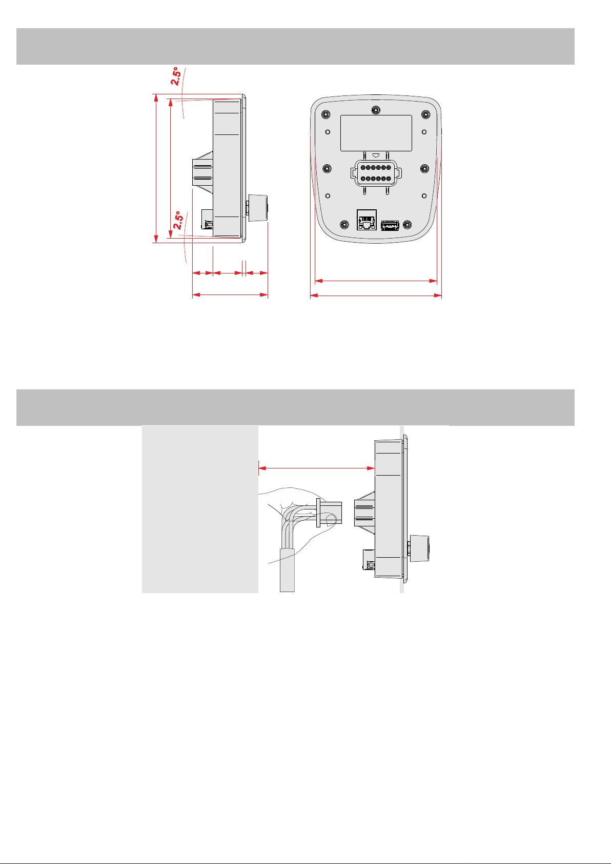
Abmessungen
113
105
17,6 25 18,7
3
64,3
128
120
Die Abbildung zeigt die Maße in Millimeter
Platzbedarf
70
Die Abbildung zeigt das Maß in Millimeter

Montageausschnitt erstellen
105,2 + 0,3
26,6
31,388,8
120,1 + 0,3
21,9 12,2
42,5
r = 9,9
r = 9,9
r= 19,9
r=19,
9
r =399,9
r=399,9
Nr.
Beschreibung Nr.
Beschreibung
1
Umriss der Frontplatte
2
Öffnung
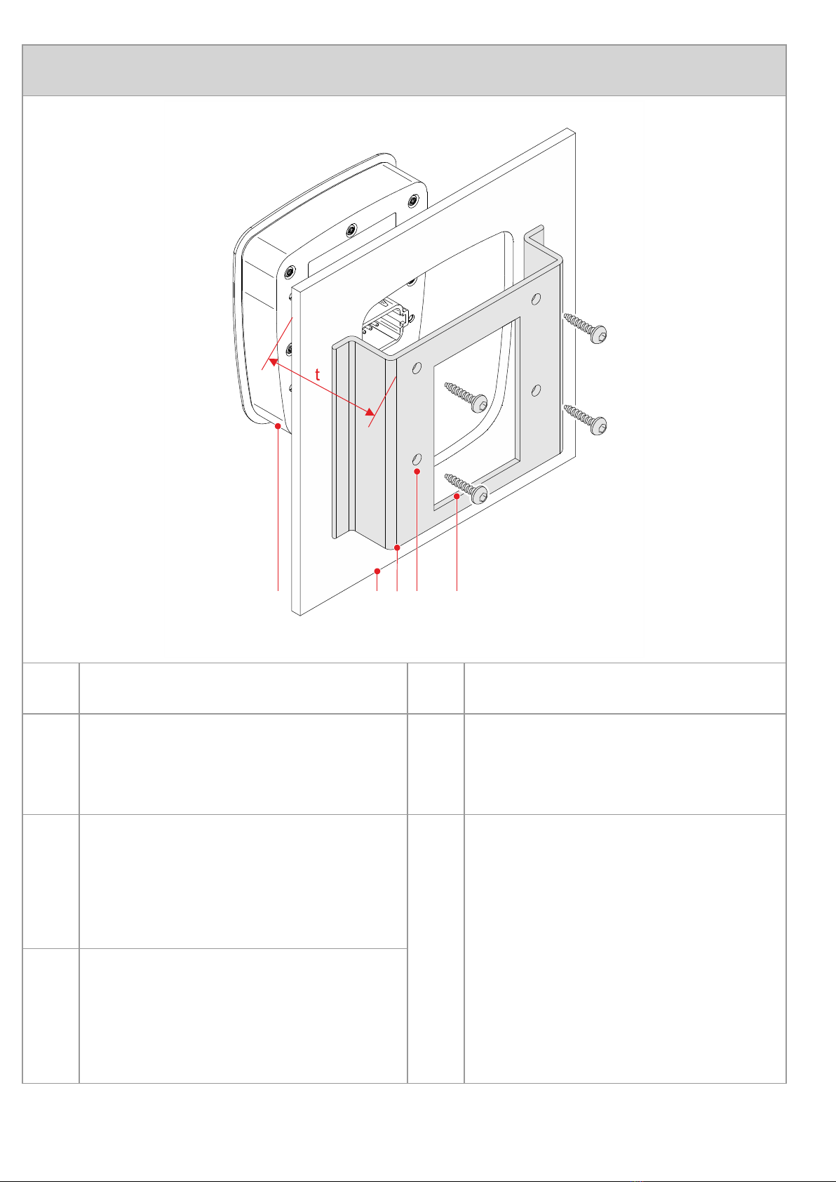
Gerät montieren
54321
Nr.
Beschreibung
Nr.
Beschreibung
1
JVM-104
4
4 x Bohrung zur
Befestigung des
JVM-104
2
Montageplatte mit
Öffnung für das
Bediengerät
5
4 x selbstfurchende
Schraube
Schraubenmaß:
4 x 9 + t
3
Winkel zur Befestigung
mit Öffnung für die
Stecker
Anzugsmoment:
1,6 Nm ± 10 %
Maximale Schraubtiefe:
12 mm
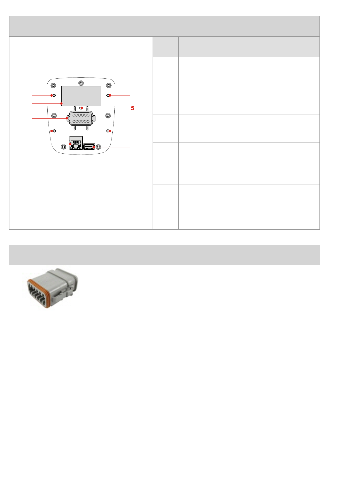
Schnittstellen und Anschlüsse im Überblick
Nr.
Beschreibung
1
6
1
1
1
2
3
4
1
Bohrung zur Befestigung
des Bediengeräts,
max. 12 mm tief
2
Typenschild
3
12-poliger Gerätestecker
(Deutsch)
4
Ethernet-Buchse -
Übertragungsrate:
10 MBit/s, 100 MBit/s
5
Druckausgleichselement
6
USB-Buchse -
USB 2.0 mit Host
Gegenstück zum 12-poligen Gerätestecker
Hersteller:
Deutsch
Herstellerartikelnu
mmer
- Gehäuse:
DT06-12S
- Arretierungskeil:
W12S
- Crimpkontakt
(Buchse):
0-462-201-16141
Anschließbarer
Adernquerschnitt:
1,0 ... 1,5 mm2
(AWG 18 ... 26)
Anschlussbeschreibung Gerätestecker mit
Verpolschutz
Sicht auf die Geräterückseite:
Pin
Beschreibung
1
Bezugspotenzial GND
2
Multifunktionsausgang PA1
3
Multifunktionsausgang PA2
4
Multifunktionsausgang PA3
5
Multifunktionsausgang PA4
6
Versorgungsspannung UB für die Logik des Geräts
Spannung: DC 12 V oder DC 24 V
Maximaler Strom: 2 A
7
Versorgungsspannung UB_PA für
Multifunktionsausgänge
Spannung: DC 12 V oder DC 24 V
Maximaler Strom: 10 A
8
Steuersignal Zündung POWER_ON
9
CAN1_L
10
CAN1_H
11
Multifunktionseingang MFQE1
12
Multifunktionseingang MFQE2

Technische Daten
Display:
3,5"-TFT-Farbdisplay,
320 x 240 Pixel
Bedienung:
4 Funktionstasten mit
Hintergrundbeleuchtung,
Digipot, Touch
Betriebssystem:
Microsoft Windows CE 6.0
Betriebstemperatur:
-20 °C ... +60 °C
Lagertemperatur:
-20 °C ... +70 °C
Schutzart:
Frontseitig: IP65
Rückseitig: IP20
Schnittstellen:
1 x USB 2.0 Host, Ethernet
10/100 BASE-TX, RJ45,
1 x CANopen®
Multifunktionsausgänge
(über Deutsch-Stecker):
4 x: PA1 ... PA4
Funktionen der
Ausgänge:
PWM
Digitaler Ausgang
1 H-Brücke (PA3 mit PA4)
High-Side-Ausgänge
2 x: Digitaler
Active-High-Eingang
Maximaler
Ausgangsstrom des
digitalen Ausgangs:
2,5 A mit
Diagnosemöglichkeit
PWM-Frequenz:
100 Hz ... 1 kHz,
Auflösung 0,1 %
Schaltschwelle des
digitalen
Active-High-Eingangs:
Aus: Min. 4,0 V, < 0,5 mA,
Ein: Max. 1,6 V, > 3,5 mA

Technische Daten
Multifunktionseingänge
(über Deutsch-Stecker):
2 x: MFQE1, MFQE2
Funktionen der
Eingänge:
Spannungsmessung
Strommessung
Digitales Eingangssignal
Frequenzmessung
Zählerfunktion
Messbereiche:
Spannung
0 ... 15 V
Strom
0 ... 20 mA
Eingangswiderstände:
Spannung
50 k
Ω
Strom
120
Ω
Schaltschwelle des
digitalen
Active-High-Eingangs:
Ein: Min. 2,0 V
Aus: Max. 1,0 V
Eingangswiderstand des
digitalen
Active-High-Eingangs:
50 k
Ω
Frequenzbereich:
0,1 Hz ... 10 kHz (Tor- oder
Periodenzeit), 0,1 %
Duty-Cyle-Frequenzeing
ang:
Mindestens 25 µs
Schaltschwelle bei
Frequenzmessung und
Zähler:
Ein: Min. 4,7 V
Aus: Max. 2,5 V
Anschluss eines
NAMUR-Sensors:
Ist möglich
Zulässiger
Spannungsbereich:
DC 8 V ... DC 32 V,
gemäß ISO 7637
Verpolschutz:
Eingebaut, Load-Dump bis
70 V
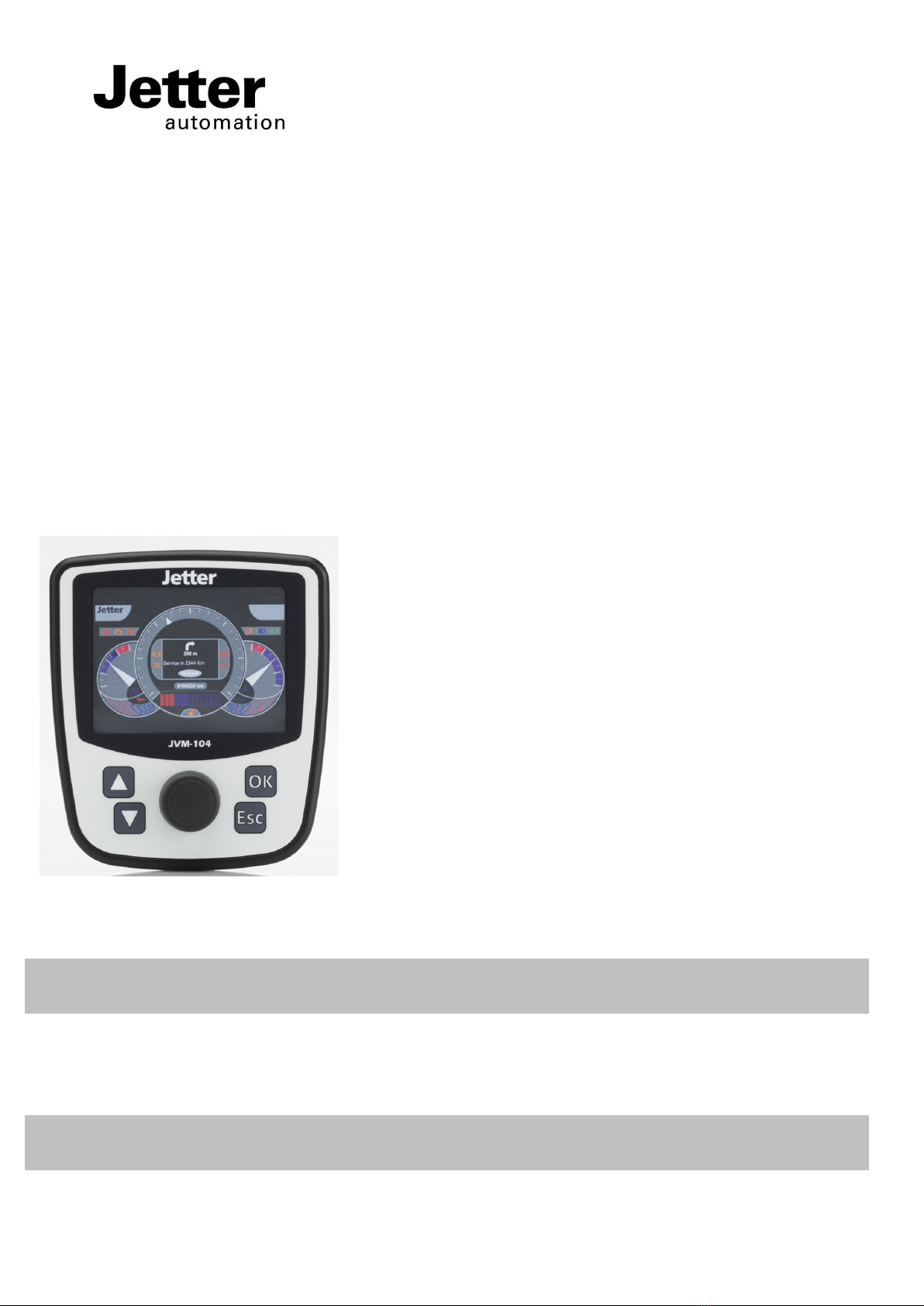
JVM-104
HMI
Jetter AG
Communication:
Graeterstrasse 2
E-mail - Sales:
sales@jetter.de
D-71642 Ludwigsburg
E-mail - Hotline:
hotline@jetter.de
Germany
Phone - Hotline:
+49(0)7141/2550-
444
Installation Manual
Item # 60878547 | Revision 1.12
May 2015 / Printed in Germany
Download the user manual from
www.jetter.de, Support > Downloads.
Scope of delivery
1 x
10001027
JVM-104-K00-O02
1 x
60878547
Installation manual
Accessories
1 x
60880138
Fastening kit
Dimensions
113
105
17.6 25 18.7
3
64.3
128
120
(All dimensions in mm)
Required space
70
(All dimensions in mm)

Cutting out the installation opening
42.5
105.2 + 0.3
26.6
31.3
88.8
120.1 + 0.3
21.9 12.2
r = 9.9
r = 9.9
r=19.9
r=19.
9
r =399.9
r=399.9
No.
Description No.
Description
1
Outline of the front
panel
2
Opening

Mounting
54321
No.
Description
No.
Description
1
JVM-104
4
4 x screw holes for
screwing down the
JVM-104
2
Panel with opening for
accommodating the HMI 5
4 x self-tapping screw
Screw size:
4 x 9 + t
3
Fastening bracket with
opening for connector
Tightening torque:
1.6 Nm ± 10 %
Maximum screw-in
depth: 12 mm

Overview - Interfaces and connections
No.
Description
1
6
1
1
1
2
3
4
1
Screw holes for fastening
the HMI.
Max depth: 12 mm
2
Nameplate
3
12-pin plug (male) by
Deutsch
4
Ethernet port -
Bit rate: 10 MBit/s,
100 MBit/s
5
Pressure compensation
membrane
6
USB port -
USB 2.0 with host
Mating connector (female) for 12-pin plug
Manufacturer:
Deutsch
Manufacturer's
item number
- Housing:
DT06-12S
- Locking wedge:
W12S
- Crimp contact
(jack):
0-462-201-16141
Wire size:
1.0 ... 1.5 mm2
(AWG 18 ... 26)

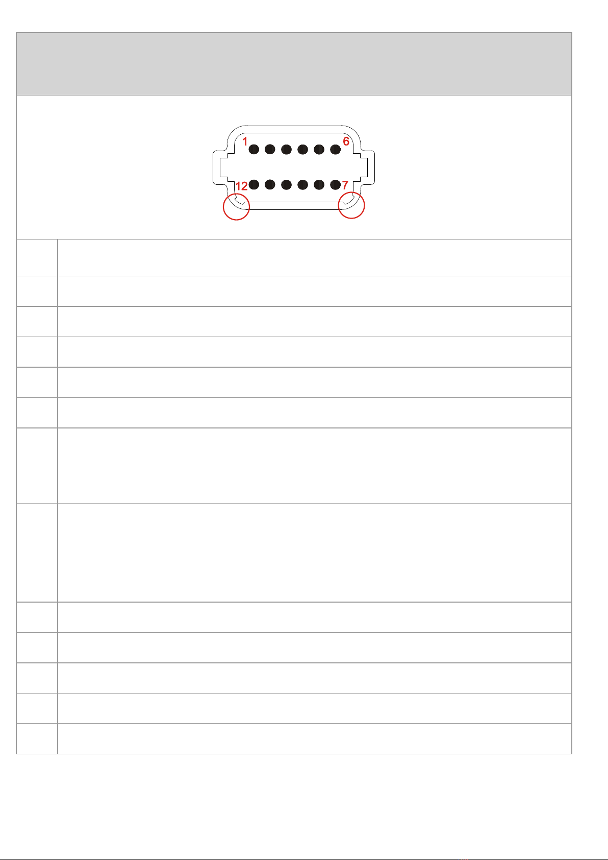
Male connector with protection against polarity
reversal - Pin assignment
View to the rear side of the HMI:
Pin
Description
1
Reference potential (GND)
2
Multi-purpose output PA1
3
Multi-purpose output PA2
4
Multi-purpose output PA3
5
Multi-purpose output PA4
6
Power supply UB for logic circuits
Voltage: DC 12 V or DC 24 V
Maximum current: 2 A
7
Power supply UB_PA for multi-purpose outputs
Voltage: DC 12 V or DC 24 V
Maximum current: 10 A
8
Ignition control signal POWER_ON
9
CAN1_L
10
CAN1_H
11
Multi-purpose input MFQE1
12
Multi-purpose input MFQE2

Technical specifications
Display:
3.5" TFT color display,
(320 x 240 pixel)
Operation:
4 function keys with
background lighting, digipot,
touch
Operating system:
Microsoft Windows CE 6.0
Operating temperature:
-20 °C ... +60 °C
Storage temperature:
-20 °C ... +70 °C
Degree of protection:
Front panel: IP65
Rear panel: IP20
Interfaces:
1 x USB 2.0 host, Ethernet
10/100 BASE-TX, RJ45,
1 x CANopen®
Multi-purpose outputs
(via Deutsch connector):
4 x: PA1 ... PA4
Functions of outputs:
PWM
Digital output
1 H-bridge (PA3 with PA4)
High-side outputs
2 x: Digital active-high input
Maximum output current
of digital output:
2.5 A with diagnostics feature
PWM frequency:
100 Hz ... 1 kHz,
resolution 0.1 %
Operating point of digital
active-high input:
OFF: min. 4.0 V, < 0.5 mA,
ON: max. 1.6 V, > 3.5 mA

Technical specifications
Multi-purpose inputs
(via Deutsch connector):
2 x: MFQE1, MFQE2
Functions of inputs:
Voltage measuring
Current measuring
Digital input signal
Frequency measuring
Counter function
Measuring ranges:
Voltage
0 ... 15 V
Current
0 ... 20 mA
Input resistors:
Voltage
50 k
Ω
Current
120
Ω
Operating point of digital
active-high input:
ON: Min. 2.0 V
OFF: Max. 1.0 V
Input resistance of digital
active-high input:
50 k
Ω
Frequency band:
0.1 Hz ... 10 kHz (gate time or
period), 0,1 %
Duty cycle frequency
input:
25 µs min.
Operating point for
frequency measurement
and counter:
ON: Min. 4.7 V
OFF: Max. 2.5 V
NAMUR sensor:
Supported
Permissible voltage range:
DC 8 V ... DC 32 V,
to ISO 7637
Protection against polarity
reversal:
Integrated, load-dump up to
70 V
Other manuals for JVM-104
1
This manual suits for next models
2
Table of contents
Languages:
Other Jetter Industrial Equipment manuals


