2
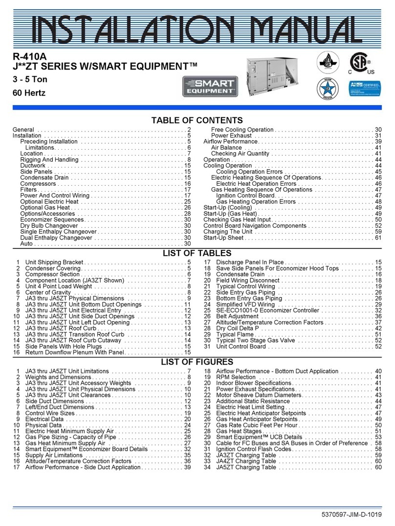
TABLE OF CONTENTS
1.0 SAFETYINFORMATION............................................3
2.0 ENERAL .......................................................4
2.1 CheckingProductReceived......................................4
2.2 Application...................................................4
2.3 Dimensions ..................................................5
2.4 ElectricalandPhysicalData .....................................6
3.0 LOCATIN UNIT..................................................6
3.1 CorrosiveEnvironment .........................................6
3.2 CondenserLocation............................................7
3.3 OperationalIssues.............................................7
3.4 or Condensers With Space Limitations . . . . . . . . . . . . . . . . . . . . . . . . . . . . 7
3.5 CustomerSatisfactionIssues ....................................7
3.6 ProperInstallation.............................................7
3.7 UnitMounting.................................................7
3.8 actory-Preferred Tie-Down Method . . . . . . . . . . . . . . . . . . . . . . . . . . . . . . . 8
4.0 REFRI ERANTCONNECTIONS .....................................8
5.0 TOOLS REQUIRED FOR INSTALLIN & SERVICIN R-410A MODELS . . . . . 8
5.1 SpecificationsofR-410A........................................9
5.2 Quick Reference Guide for R-410A . . . . . . . . . . . . . . . . . . . . . . . . . . . . . . . 10
6.0 REPLACEMENTUNITS............................................10
7.0 EVAPORATORCOIL..............................................10
8.0 REPLACEMENTUNITS............................................11
9.0 INTERCONNECTIN TUBIN ......................................11
9.1 VaporandLiquidLines ........................................11
9.2 MaximumLengthofLines......................................11
9.3 Outdoor Unit Installed Above Indoor Coil. . . . . . . . . . . . . . . . . . . . . . . . . . . 11
9.4 OutdoorUnitBelowIndoorCoil..................................11
9.5 TubingInstallation............................................11
9.6 TubingConnections...........................................12
9.7 LeakTesting ................................................14
10.0 EVACUATIONPROCEDURE .......................................14
11.0 STARTUPANDPERFORMANCE ...................................14
12.0 CHECKIN AIRFLOW.............................................14
13.0 CHECKIN REFRI ERANT CHAR E . . . . . . . . . . . . . . . . . . . . . . . . . . . . . . . . 15
13.1 ChargingUsingChargingChart..................................15
13.2 ChargingByWeight...........................................16
13.3 inalLeakTesting............................................16
14.0 ELECTRICALWIRIN .............................................16
14.1 Grounding ..................................................16
14.2 PowerWiring................................................16
14.3 ControlWiring ...............................................17
15.0 FIELDINSTALLEDACCESSORIES..................................17
15.1 Compressor Crankcase Heat (CCH) . . . . . . . . . . . . . . . . . . . . . . . . . . . . . . 17
15.2 TimeDelayControl(TDC)......................................17
15.3 LowAmbientControl(LAC).....................................18
15.4 High and Low Pressure Controls (HPC & LPC). . . . . . . . . . . . . . . . . . . . . . 18
16.0 SERVICE .......................................................18
16.1 Operation...................................................18
16.2 Single-Pole Compressor Contactor (CC). . . . . . . . . . . . . . . . . . . . . . . . . . . 18
17.0 TROUBLESHOOTIN ............................................19
17.1 ElectricalChecks lowChart....................................19
17.2 MechanicalChecks lowChart..................................20
17.3 SuperheatCalculation.........................................21
17.4 SubcoolingCalculation ........................................21
17.5 General ....................................................22
TroubleshootingChart.........................................22
18.0 WIRIN DIA RAMS ..............................................23
18.1 PSCDiagram................................................23
18.2 ECMDiagram ...............................................24
