Johnson Controls 6HK Series User manual

Johnson Controls Ducted Systems 6052931-UAI-A-0121
ACCESSORY KIT INSTALLATION MANUAL
Electric Heat Kit (6HK Series)
For Use with Models: AP, AE, AVC, AVV, AHR, AHE, AHV, MP, ME, MVC, RFCX*E, RFCX*P, PHE, and PCE
General information
These instructions cover installation of the 6HK series of elec-
tric heat kits with the following:
• AP, AE, AVC, AVV, AHR, AHE, AHV, RFCX*E, and
RFCX*P single-piece air handlers
• MP, ME, and MVC modular air handlers
• PHE and PCE residential packaged units
The 6HK series of electric heat kits use a single polarized plug
to easily connect the equipment power and controls.
These electric heat kits are used for applications of electric
heat, cooling with electric heat, and heat pump with electric
heat. Each of the air handler and residential packaged unit
models are approved for use with specific electric heat kits. The
unit installation instructions, technical guide, or name plate list
the possible combinations and other important electrical data
and limitations. Refer to the unit installation instructions for fur-
ther electrical specifications.
Clearance
All installations of the 6HK electric heat kits are approved for
zero clearance to combustibles when the minimum speed tap
on the blower motor is set according to the equipment installa-
tion instructions or nameplate. See the equipment installation
instructions for more information on changing motor speed
taps.
WARNING
ELECTRICAL SHOCK HAZARD
Installation or repairs made by unqualified persons can result
in hazards to you and others. Installation must conform with
local building codes or, in the absence of local codes, with
National Electrical Code ANSI/NFPA 70-1996 or current edi-
tion.
The information contained in this manual is intended for use
by a qualified service technician familiar with safety proce-
dures and equipped with the proper tools and test instru-
ments.
Shut OFF electric power at unit disconnect and/or service
panel before beginning the following procedures.
Failure to carefully read and follow all instructions in this man-
ual can result in malfunction, property damage, personal
injury, and/or death.
Verify edges of foil faced insulation are not in contact with any
exposed electrical connections.
CAUTION
Unit is approved for zero clearance to combustible material
and when equipped with electric heat a minimum clearance
of 1 in. must be maintained on all sides of the supply duct
and/or plenum for 3 ft as shown in the detail in Figure 1 for
the 20 kW and 25 kW electric heat kits only.
NOTICE
In some horizontal applications, the service disconnects on
the electric heat kits must be rotated 180° so the up position
of the disconnect is the ON position. This service disconnect
orientation change is required by UL 1995, Article 26.19 (in
reference to all circuit breakers).
!
!
Figure 1: Duct work clearance
NOTICE
The electric heat kit should be installed before the supply air
duct is attached to the supply air opening flanges.
MINIMUM CLEARANCE
1” on all sides for the first 3’
of duct from 20 & 25 kw units.
For all other heaters,
zero inch clearance on all
sides for entire length of duct.
FLEXIBLE DUCT COLLAR
NOTE:
For units applied with a roof
curb, the minimum clearance
may be reduced from 1 inch to
1/2 inch between combustible
roof curb material and the
supply duct. A0238-001
3’

6052931-UAI-A-0121
2 Johnson Controls Ducted Systems
Models
Nomenclature - electrical
Electric heat kit installation for air handlers:
AP, AE, AVC, AVV, MP, ME, MVC, AHR, AHE,
AHV, RFCX*E, and RFCX*P
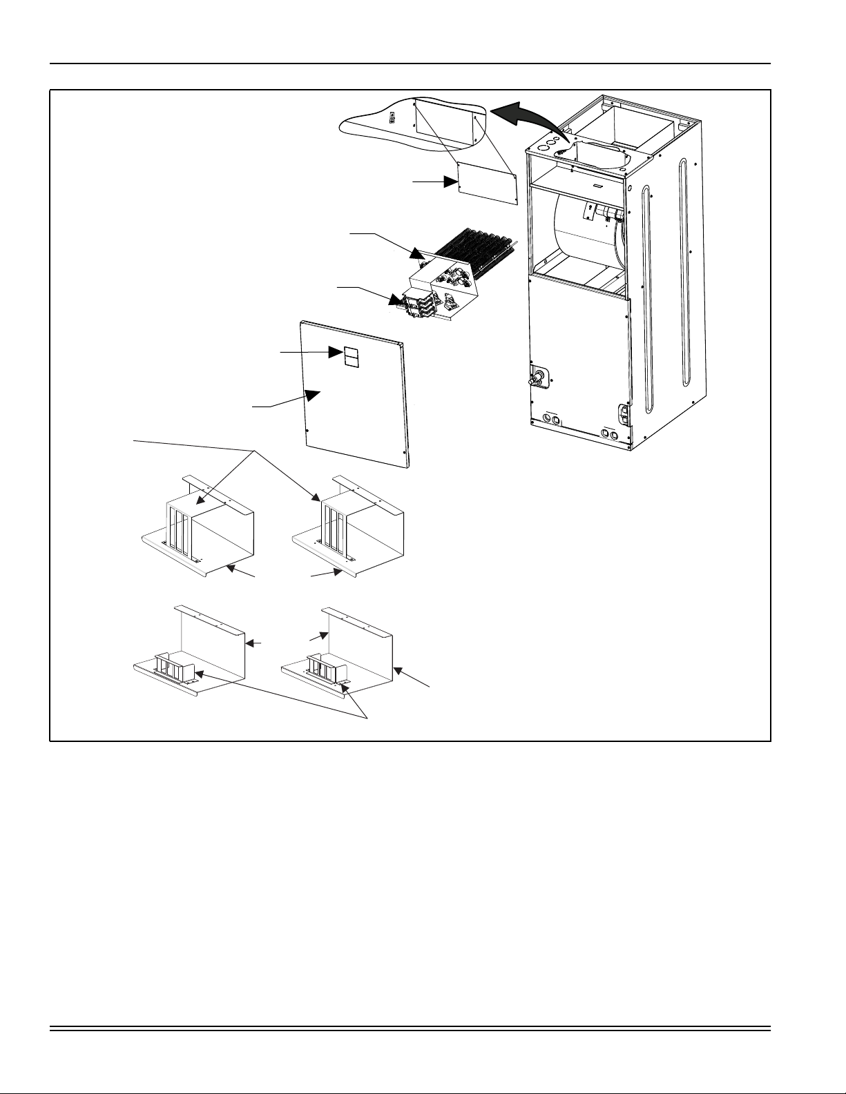
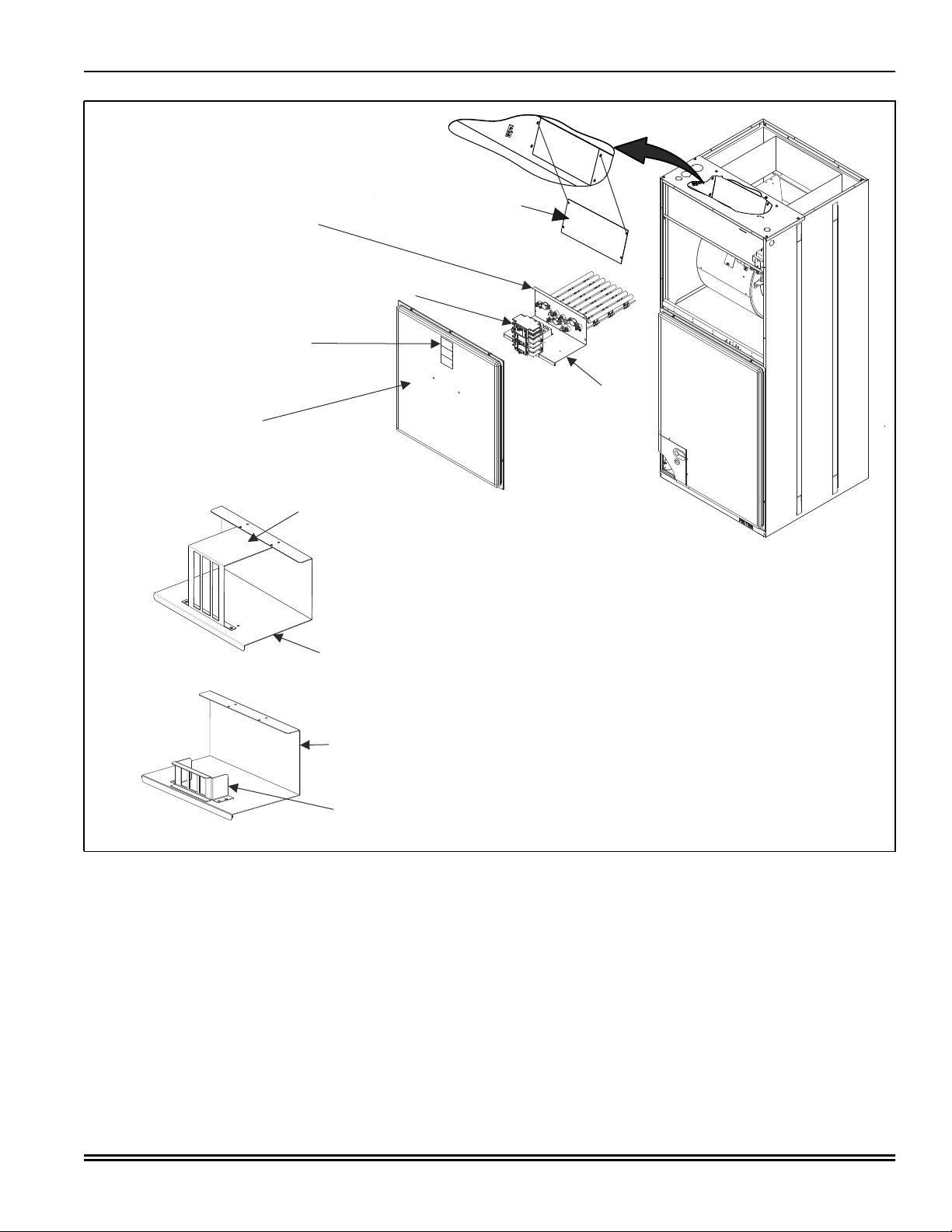
Installation is the same for all air handler operating positions:
upflow, downflow, and horizontal right or horizontal left. Install
the electric heat kit before unit installation. See Figure 3 or Fig-
ure 4 for a depiction of the components.
1. Ensure that there is no electrical power going to the unit.
2. Remove the air handler blower access panel.
3. If installing the electric heat kit in an AP, AE, AVC, AVV, MP,
ME, MVC, RFCX*E2, or RFCX*P2 model, leave the ser-
vice disconnect bracket in position A as shown in Figure 4.
Or
If installing the electric heat kit in an AHR, AHE, AHV,
RFCX*E1, or RFCX*P1 model, move the service discon-
nect bracket to position B as shown in Figure 3.
4. If the electric heat kit does not have service disconnects,
go to Step 5.
Or
If the electric heat kit has service disconnects, complete
the following before Step 5:
a. Examine the electric heat kit and take note of the num-
ber of service disconnects it has. Remove the appro-
priate number of service disconnect knockouts from
the front access panel of the air handler unit.
b. Cut the blower access panel insulation behind the ser-
vice disconnect plate and remove to open the area for
the service disconnects to protrude through the front
access panel and provide clearance for the service
disconnects and single-point wiring entry kit.
c. Add replacement non-foil faced insulation for the
exposed front panel if needed. Add rubber gasket to
the inside of the door for sealing.
5. Remove and recycle the duct cover from the back panel of
the air handler control and wiring compartment.
Table 1: Models covered
Electric
heat kit kW
at 240V
1 phase electric
heat kit1,2
(all except PHE)
1 phase electric
heat kit1,2,3
(PHE)
3 phase 208 V/230 V
electric heat kits
(PHE, PCE, AHR,
AHE, AHV, RFCX*E1,
RFCX*P1)
3 Phase 208 V/230 V
electric heat kits
(AP, AE, AVC, AVV,
RFCX*E2, RFCX*P2,
MP, ME, MVC)
3 phase 460 V
electric heat kits4
2.4 6HK(0,1)6500206 6HK(0,1)6500206 -- -- --
4.8 6HK(0,1)6500506 6HK(0,1)6500506 -- -- --
7.7 6HK(0,1)6500806 6HK(0,1)6500806 -- -- --
9.6 6HK(0,1)6501006 6HK(0,1)6501006 6HK06501025 6HK36501025 6HK06501046
12.5 6HK(1,2)6501306 6HK(1,2)6501306 -- -- --
14.4 6HK(1,2)6501506 6HK(1,2)6501506 6HK06501525 6HK36501525 6HK06501546
17.3 6HK(1,2)6501806 6HK(1,2)6501806 6HK06501825 6HK36501825 6HK06501846
19.2 6HK(1,2)6502006 6HK(1,2)6502006 6HK16502025 6HK46502025 6HK06502046
24.0 6HK(1,2)6502506 6HK(5,6)6502506 6HK16502525 6HK46502525 6HK06502546
1. (0,1) - 0 = no service disconnect or 1 = with service disconnect.
2. (1,2) - 1 = with service disconnect, no breaker jumper bar or 2 = with service disconnect and breaker jumper bar.
3. (5,6) - 5 = with service disconnect, no breaker jumper bar or 6 = with service disconnect and breaker jumper bar.
4. Use revision D or later for MP 460-V models.
6 Product category 6 = electric heat for AP, AE, AVC, AVV, MP, ME, MVC, AHR, AHE, AHV, RFCX*E, and RFCX*P residen-
tial air handlers and PHE and PCE residential packaged units
HK Family identifier HK = electric heat kit
1 Power connection
0 or 3 = terminal block
1, 4, or 5 = service disconnect
2 or 6 = service disconnect and single-point wiring kit
65 Class identifier 65 = electric heat kit
002 Electric heat, Nom. kW 002 = 2.5 kW, 005 = 5 kW, 008 = 8 kW, 010 = 10 kW, 013 = 13 kW, 015 = 15kW, 018 = 18 kW,
020 = 20 kW, 025 = 25 kW
25 Voltage code 06 = 208/230-1-60, 25 = 208/230-3-60, 46 = 460-3-60
C Style letter C = indicates sequential change of component style
D Style letter D = changed limit control cut out specification
CAUTION
Be aware that some units may have multiple power sources.
!

6052931-UAI-A-0121
Johnson Controls Ducted Systems 3
6. Install the electric heat kit as follows:
a. Position and insert the electric heat kit into the opening
in the air handler unit.
b. Align the mount holes and fasten the electric heat kit to
the air handler unit with four duct cover screws.
7. Remove and discard the air handler power connection wir-
ing that is for use without electric heat (the connector con-
taining only the red and black wires) from the 6-pin
connector.
8. Connect the 6-pin socket connector of the electric heat kit
to the control/power 6-pin connector in the air handler. The
end terminals are D-shaped to ensure polarization of the
connector.
9. Mark an X in the appropriate box on the indoor unit rating
plate for the particular electric heat kit installed.
10. Refer to the unit rating plate for the minimum blower speed
required for the electric heat kit model installed, and set the
blower speed accordingly.
CAUTION
To prevent damage, carefully pass the accessory heating ele-
ment through the rectangular opening in the discharge duct.
Element mounting plate must be secured with four screws.
!WARNING
Verify edges of foil faced insulation are not in contact with any
exposed electrical connections.
NOTICE
All wiring must comply with local and National Electrical Code
requirements. Read and heed all unit caution labels.
NOTICE
An optional service disconnect cover can be applied to seal/
protect the Service Disconnects (S1-02435672000).
!
Figure 2: Typical electric heat kit installations - air handler
UPFLOW
HORIZONTAL RIGHT
HORIZONTAL LEFT
HEAT
HEAT
HEAT
DOWNFLOW
HEAT
A0330-001

6052931-UAI-A-0121
4 Johnson Controls Ducted Systems
Note: When installing the electric heat kit in AHR, AHE, AHV, RFCX*E1, and RFCX*P1 models, adjust the electric heat kit service
disconnect bracket to position B as shown in Figure 3. To do so, remove four mount screws, move the service disconnect bracket to
position B, and secure the service disconnect bracket with the four screws. When installing the electric heat kit in AP, AE, AVC, AVV,
MP, ME, MVC, RFCX*E2, and RFCX*P2 models, the electric heat kit service disconnect bracket remains in position A.
Figure 3: Air handler electric heat kit installation - AHR, AHE, AHV, RFCX*E1, and RFCX*P1
%/2:(5$&&(663$1(/
$
'8&7&29(5
5HPRYHIRUKHDWHU
NLWLQVWDOODWLRQ
+($7(5.,7
6OLGHKHDWHULQWRDLU
KDQGOHUDQGDWWDFK
ZLWKIRXUGXFWFRYHUVFUHZV
),(/'6833/<:,5,1*
&RQQHFWWROHIWVLGH
6(59,&(',6&211(&7.12&.2876
5HPRYHLIKHDWHUNLWKDVVHUYLFH
GLVFRQQHFW
326,7,21$ 326,7,21%
%5$&.(7
%5$&.(7
%5$&.(7
6+257
6(59,&(
',6&211(&7
%5$&.(7
7$//
6(59,&(
',6&211(&7
%5$&.(7

6052931-UAI-A-0121
Johnson Controls Ducted Systems 5
Note: When installing the electric heat kit in AP, AE, AVC, AVV, MP, ME, MVC, RFCX*E2, and RFCX*P2 models, leave the electric
heat kit service disconnect bracket (tall or short) in position A, as shown in Figure 4. Do not move the electric heat kit service discon-
nect bracket to another position.
Figure 4: Air handler electric heat kit installation - AP, AE, AVC, AVV, MP, ME, MVC, RFCX*E2, and RFCX*P2
'8&7&29(5
5HPRYHIRUKHDWHU
NLWLQVWDOODWLRQ
%/2:(5$&&(663$1(/
6(59,&(',6&211(&7.12&.2876
5HPRYHLIKHDWHUNLWKDVVHUYLFHGLVFRQQHFWV
+($7(5.,7
6OLGHKHDWHULQWRDLU
KDQGOHUDQGDWWDFK
ZLWKIRXUGXFWFRYHUVFUHZV
),(/'6833/<:,5,1*
&RQQHFWWROHIWVLGH
326,7,21$
7$//
6(59,&(
',6&211(&7
%5$&.(7
%5$&.(7
%5$&.(7
%5$&.(7
$
6+257
6(59,&(
',6&211(&7
%5$&.(7

6052931-UAI-A-0121
6 Johnson Controls Ducted Systems
Electric heat kit installation for residential
packaged units: PHE and PCE
Installation is the same for PHE and PCE models. Install the
electric heat kit before unit installation. See Figure 5 for a depic-
tion of the components.
1. Ensure that there is no electrical power going to the unit.
2. Remove the electrical/controls access panel.
3. Remove and discard the patch plate exposing the opening
for the installation of the electric heat kit. See Figure 5.
4. Install the electric heat kit.
5. Connect the 6-pin socket connector of the electric heat kit
to the control/power 6-pin connector in the residential pack-
aged unit. The end terminals are D-shaped to ensure
polarization of the connector.
6. Mark an X in the appropriate box on the outdoor unit rating
plate for the particular electric heat kit installed.
7. Refer to the unit rating plate for the minimum blower speed
required for the electric heat kit model installed, and set the
blower speed accordingly.
.
CAUTION
To prevent damage, carefully pass the accessory heating ele-
ment through the open rectangular mounting position. Ele-
ment mounting plate must be secured with four screws.
NOTICE
The service disconnects on the electric heat kit must be
rotated 180° so that the UP position of the disconnect is the
ON position. This service disconnect orientation change is
required by UL 1995, Article 26.19 (in reference to all circuit
breakers).
!WARNING
Verify edges of foil faced insulation are not in contact with any
exposed electrical connections.
NOTICE
All wiring must comply with local and National Electrical Code
requirements. Read and heed all unit caution labels.
!
Figure 5: Residential packaged unit electric heat kit installation - PHE and PCE
A0256-001

6052931-UAI-A-0121
Johnson Controls Ducted Systems 7
Line power connections
Power can be brought into the air handler through the outlet air
end of the unit (top left when the unit is vertical) or the left-side
panel. For the residential packaged unit, power can be brought
into the electric/controls area through the power supply provi-
sions in the bottom or right side of the unit. To minimize air leak-
age for any unit, seal the field wiring entry point.
Field wiring connects to electric heat kits with service discon-
nect or terminal block depending on the electric heat kit model.
The multiple circuit, single-phase electric heat kits have options
for a single power supply. For the 3 phase 20 kW and 25 kW
electric heat kits with multiple circuits, a single-point power
accessory kit can be ordered separately. A ground lug is pro-
vided on the kits. Refer to the unit installation instructions for
electrical specifications. See Figure 6 and Figure 7.
Figure 6: Electric heat kit connection
FACTORY WIRING
Attached to this side -
no need for removal.
TERMINAL BLOCK OR
SERVICE DISCONNECTS
May have 1, 2, or 3 service disconnects.
FIELD SUPPLIED WIRING
Attaches to left side.
A0241-001
Figure 7: Air handler and residential packaged unit electric heat power
),(/'32:(5:,5,1*
9WKUX9RU9
&20321(17&2'(6
*1'*5281'/8*
6'6(59,&(',6&211(&7
&.7&,5&8,7
*1'
-803(5%$5
6,1*/(6285&(32:(5
08/7,6285&(32:(5
6,1*/(6285&(32:(5
:,7+-803(5%$5
6'
32:(5
6833/< /
/
7(50,1$/%/2&.25
6(59,&(',6&211(&7
32:(5
6833/<
*1'
/
/
6,1*/(6285&(32:(5
7(50,1$/%/2&.25
6(59,&(',6&211(&7
*1'
32:(5
6833/< /
/
/ &.7
&.7
32:(5
6833/<
6'
6'
*1'
/
/
/
/
/
/
08/7,6285&(32:(5
32:(5
6833/<
&,5&8,7621.:.:
&,5&8,7621.:
*1'
/
/
/
/
/
/
&.7 6'
6'
6'
&.7
&.7
&,5&8,7621.:.:
&,5&8,7621.:
6,1*/(3+$6((/(&75,&+($7237,216
7+5((3+$6((/(&75,&+($732:(5237,216
$
6,1*/(6285&(32:(5
:,7+6,1*/(32,17
32:(5$&&(6625<
32:(5
6833/<
6'
*1'
/
/
/ /
/
/
6'
/
/
/
6'
6'

Subject to change without notice. Published in U.S.A. 6052931-UAI-A-0121
Copyright © 2021 by Johnson Controls. All rights reserved. Supersedes: 5181703-UAI-C-0818
York International Corp.
5005 York Drive
Norman, OK 73069
Electric heat kits and operating controls Low-voltage control connections
The low-voltage transformer is standard on all models.
The 24-V power supply is provided by an internally wired low-
voltage transformer, which is standard on all air handler and
residential packaged unit models. Field supplied low-voltage
wiring can exit the unit on the top-right corner of the air handler
or the right-side panel of the air handler. See Figure 3 or Figure
4. Residential packaged unit models have provisions for low-
voltage wiring exits in the bottom or right side of the unit. See
Figure 5. Remove the required knockout and pierce the foil
faced insulation to allow the wiring to pass through. Use as
small a hole as possible to minimize air leakage. Install a 7/8-in.
plastic bushing in the selected hole and keep low-voltage wiring
as short as possible inside the control box. To further minimize
air leakage, seal the wiring entry point at the outside of the unit.
Connect the field wiring at the screw terminals of the control
board or on low-voltage wiring leads using twist-on wire con-
nectors.
NOTICE
For blower speed connections, electrical information and wir-
ing diagrams, see indoor unit installation instructions.
NOTICE
The electric heat kits have both auto resettable and fusible
link thermal limit controls.
If failure occurs, this fusible link thermal limit control must be
replaced with a direct replacement.
NOTICE
All wiring must comply with local and national electrical code
requirements. Read and heed all unit caution labels.
This manual suits for next models
35
Table of contents
Other Johnson Controls Heater manuals
Popular Heater manuals by other brands

Holmes
Holmes HCH41261 owner's guide

ECOMAT 2000
ECOMAT 2000 CLASSIC PLUS Instructions for use

Blaze
Blaze 40E product manual

FläktGroup
FläktGroup ACJB INSTALLATION, OPERATION, MAINTENANCE AND SPARE PARTS

Schou
Schou 69661 instruction manual

Spacio Innovations
Spacio Innovations WEXSTAR WS-4W installation instructions