uniwatt AUBH1802 User manual

INSAUBH1017
BATHROOM FAN HEATER
REPLACEMENT COMPONENT LIST INCLUDED
AUBH1802
S
Y
S
T
È
M
E
Q
U
A
L
I
T
É
C
E
R
T
I
F
I
É
-
R
E
G
I
S
T
E
R
E
D
Q
U
A
L
I
T
Y
S
Y
S
T
E
M
UNIWATT is a line of products manufactured by STELPRO. For more information please contact customer service.
USER’S GUIDE
This unit
complies with
CSA and UL
standards

INSAUBH1017
2
WARNING
Before installing and operating this product, the user and/or installer must read, understand and follow these instructions and keep them
handy for future reference. If these instructions are not followed, the warranty will be considered null and void and the manufacturer deems
no further responsibility for this product.
This product must be installed by a qualied person and connected by a certied electrician, according to the electrical and
building codes effective in your region.
The following instructions must be adhered to in order to avoid personal injuries or property damages, serious injuries and potentially fatal
electric shocks.
Protect the heating unit with the appropriate circuit breaker or fuse, in accordance with the nameplate.
Make sure the line voltage (volt) is consistent with that indicated on the unit’s nameplate.
Switch off the power at the circuit breaker/fuse before installing, repairing and cleaning the unit.
Make sure the unit is appropriate for the intended use (if needed, refer to the product catalog or a representative). Use this heater only as described in this manual.
Any other use not recommended by the manufacturer may cause re, electric shock, or injury to persons. Do not use outdoors.
RECOMMENDED HEATING CAPACITY: 1.25 W/cubic foot
It corresponds to 10 W/square foot based on a standard ceiling height of 8 feet. The recommended capacity is usually sufcient for normal heating needs.
Please note that the insulation quality of walls and windows are some of the factors that inuence heat losses, which modify the required capacity to heat a room.
If needed, refer to a specialist who will be able to calculate these heat losses and optimize the required capacity or consult the “Online heating calculation” section
of the Stelpro website (residential buildings). To heat a large room and to increase your comfort, it is recommended to install several units instead of one. For
example, 2 X 1000 W rather than 1 X 2000 W.
Do not install the unit where objects or pieces of furniture could be heat damaged.
If the unit’s capacity is insufcient for the size of the room, it will be in operation continuously, and may become defective earlier and turn yellow.
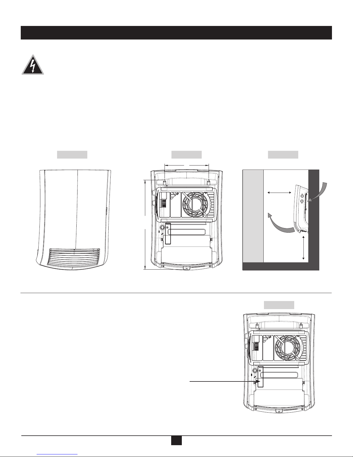
Respect distances and positions indicated in the installation section.
If the installer or user modies the unit, they will be held responsible for any damage resulting from this modication, and the CSA certication could be void.
This unit must not come into contact with a water source and must be protected from splashes (e.g. a wet mop). Do not use it if any part has been immersed.
Moreover, do not turn it on or off when standing in water or if your hands are wet.
When mounting the unit, make sure that the anchorage used can support the total weight of the unit with the mounting brackets.
When cutting or drilling into a wall, do not damage electrical wiring and other hidden utilities.
When starting up the unit for the rst time or after a long period, it is normal that it produces some temporary odours and whitish smoke.
Because this unit is hot when in use, it may pose risks even in normal operation. Therefore, be careful and responsible when using it. To avoid burns, do not let bare
skin touch hot surfaces. Let the unit cool down for a few minutes before handling it (it stays warm for some time after shut-down). Extreme caution is necessary
when any heater is used by or near children or invalids and whenever the heater is left operating and unattended.
Do not install on a wall behind a door.
CAUTION – High temperature; risk of re. Keep electrical cords, drapery, furnishings, and other combustibles at least 3 feet from the front of the heater and away from
the side and rear.
Never block air vents (with objects or other items). You risk damaging the heater and the obstruction could lead to electric shock or overheating, which could
result in a re.
Do not insert or allow foreign objects to enter any air vent as this may cause electric shocks, a re or damages to the unit.
This unit has hot and arcing or sparking parts inside. It is not designed to be used or stored in wet areas or areas containing ammable liquids, combustible materials
or corrosive, abrasive, chemical, explosive and ammable substances such as, but not limited to, gasoline, paint, chlorine, sawdust and cleaning products.
Some areas are dustier than others. Thus, it is the user’s responsibility to evaluate if the unit must be cleaned based on the amount of dirt accumulated on and
inside air vents. Accumulated dirt can lead to a component malfunction or give a yellowish colour to unit. Failure to install and maintain unit in accordance with
these instructions poses a re hasard.
Thermal protection activation indicates that the unit has been subjected to abnormal operating conditions. If the thermal protection remains activated or activates
and deactivates repeatedly, it is recommended that a qualied electrician or a certied repair centre examine the unit in order to make sure it is not damaged.
(Refer to the limited warranty.)
Before unplugging the unit, all controls must be in the “OFF” position and the current from the main breaker panel should be cut. (The general switch may be used
also, if included.)
If the unit is damaged or defective, discontinue use, cut off power supply at circuit breaker and contact a certied electrician or certied repair centre. (Refer to the
limited warranty.)
Note: When a part of the product specication must be changed to improve operability or other functions, priority is given to the product specication itself. In such
instances, the instruction manual may not entirely match all the functions of the actual product. Therefore, the actual product and packaging, as well as the name and
illustration, may differ from the manual.
IMPORTANT INSTRUCTIONS
SAVE THESE INSTRUCTIONS

INSAUBH1017
3
NOTES:
This unit must be permanently secured to one
of the bathroom walls and must only be used to
heat the room where it is installed.
Make sure the main power supply complies
with the rating plate: 240/208 V AC, 60/50 Hz.
Never let children play with the unit. Caution!
When the unit is on, the air outlet grill can reach
very high temperatures (more than 176 °F).
Never use this unit within arm’s reach while in
the shower, the bathtub or near a sink.
Position the unit so the plug is easy to reach.
Never secure the unit to walls made of syn-
thetic materials.
The fan heater must be wall mounted in a verti-
cal position only.
SPECIFICATIONS
TECHNICAL DRAWINGS
FORCED AIR HEATER
VOLTS 240 / 208 V
WATTS 1800 / 1350 W
AMPS 8.3 / 6.49 A
WEIGHT 6.2 LB
DEPTH 4 7/8”
WIDTH 11 9/16”
HEIGHT 16 3/16”
TECHNICAL DRAWINGS AND SPECIFICATIONS
12"
12"
16 3/16"
11 9/16"
FRONT
f
f
4 7/8"
SIDE
3 3/8"
4"
14 5/16"
7 1/16"
7/8" JUNCTION BOX
REAR
L2
ALIMENTATION
POWER SUPPLY
M
GND
PL
E2
L1
T
TH
E1
FL
A
1041 Parent Saint-Bruno
J3V 6L7 (450)-441-0101 DATE:
APP. PAR:
TITRE: UBH-01
SP
05-04-13
MISE À LA TERRE
MINUTERIE
OUTSIDE CONNECTION
TIMER
CONNEXION EXTÉRIEURE
G14
GND
T
GROUND
THERMOSTATTH
ÉLÉMENT
ELEMENT
MOTOR
MOTEURM
E
PROTECTION THERMIQUE
THERMAL PROTECTION
A
LUMIÈRE TÉMOIN
PILOT LIGHT
PL FUSIBLE
FUSE LINK
FL
RÉVISION: LKDessinateur:

INSAUBH1017
4
CAUTION – HIGH TEMPERATURE; RISK OF FIRE. KEEP
ELECTRICAL CORDS, DRAPERY, FURNISHINGS, AND OTHER
COMBUSTIBLES AT LEAST 3 FEET FROM THE FRONT OF THE
HEATER AND AWAY FROM THE SIDE AND REAR.
TO REDUCE THE RISK OF FIRE, DO NOT STORE OR USE
GASOLINE OR OTHER FLAMMABLE VAPORS AND LIQUIDS IN THE VICIN-
ITY OF THE HEATER. DO NOT MOUNT IN CONTACT WITH COMBUSTIBLE
MATERIAL. DO NOT MOUNT IN CLOSE PROXIMITY TO ANOTHER UNIT.
- The unit must be secured to a wall, 12 in away from the oor and adjacent
walls (Fig.1). A minimum distance of 24 in from the oor to the bottom of the
unit must be respected when the towel holder is installed.
- THE UNIT CANNOT BE COVERED OR HIDDEN BY A DOOR.
- Drill three holes with a diameter slightly smaller than the one for the plastic
pins provided.
- Insert the pins.
- Insert the two top screws provided, leaving a gap of 5/16 in between the
screw head and the wall (Fig.2).
- Hang the unit on the two installed screws while holding it securely in your
hands; CAUTION! BEFORE LETTING GO OF THE UNIT, CHECK THAT IT
IS SECURELY HUNG ON THE TWO SCREWS.
- Secure the unit with the third screw at the bottom (Fig.2).
- Figure 3 on the right indicates the airow generated by the heater. This air
corridor must remain clear in order to allow good air circulation and to ensure
that the unit operates efciently.
- Leave at least 12 inches in front of the unit.
- Do not install the heater below an electrical outlet.
INSTALLATION
FIGURE 1
12"
2
2
2
Minimum
12"
Minimum
12"
Minimum
WALL WALL
FLOOR
FIGURE 3
12"
12"
AIR
INLET
AIR
OUTLET
INSTALLATION
N.B. Cut off power supply at circuit breaker/fuse before proceeding to the instal-
lation and wiring connections.This product must be connected by a certied
electrician, according to the electrical and building codes effective in your re-
gion. Consult the wiring plan found on the unit.
- Make the electrical connections inside the junction box located at the back
of the unit (Fig.4).
- Installation of this product must be made in accordance with all national and
local building codes.
- The electrical connections must be made with a 12-gauge 2-conductor wire.
- This unit is double insulated. Because of the insulation feature, it does not
need to be grounded.
ELECTRICAL CONNECTION FIGURE 4
JUNCTION
BOX
FIGURE 2
6"
14 5/16"

INSAUBH1017
5
WARNING: THE HEATER MUST BE PROPERLY INSTALLED BEFORE IT IS USED.
The fan heater has two knobs, one for the thermostat and one for the 60-minute timer.
The unit has two operating modes.
OPERATION AND MAINTENANCE
ROOM WARM-UP WITH
TEMPERATURE CONTROL
From the position farthest left, turn the thermostat knob clockwise until a click-
ing noise is heard; the unit is turned on at a power of 1000 W and the pilot light
turns on.
The thermostat maintains the required room temperature by automatically turn-
ing on and off the fan heater. The more you turn the knob clockwise, the higher
the constant temperature will be. The thermostat maximum setting is about 86 °F
and the minimum setting is about 41 °F.
SETTING THE THERMOSTAT:
With a room temperature above 86 °F, it is normal for the thermostat to not turn
on the fan heater, even at the maximum setting.
With a room temperature too low (under 41 °F), it is normal for the thermostat to
maintain the unit on, even at the minimum setting.
TO OPTIMIZE THERMOSTAT USAGE:
- Set the thermostat to the maximum setting and operate the unit until a com-
fortable temperature is reached;
- Then, turn the thermostat knob counter-clockwise until a click is heard (the
unit is turned off);
- Slightly turn (just a little) the thermostat knob clockwise;
- At this setting, the thermostat maintains the chosen room temperature.
QUICK ROOM WARM-UP
With the room temperature set at the required level, turn the timer knob to se-
lect the required operating time. The unit operates at 1800 W for the set time
to quickly heat the room and then maintains the room temperature set by the
thermostat at a power of 1000 W.
SAFETY IN CASE OF ABNORMAL OPERATION
In the event the unit overheats, the built-in protection system automatically de-
activates the heating elements and the motor, effectively stopping the fan heater
operation. In this case, the unit is inactive, but the warning lamp is on.
PROCEDURES TO BE FOLLOWED:
- Turn off the fan heater and let it cool for about 15-20 minutes. It is imperative
to set the thermostat and the timer to the “OFF” position in order to re-start it;
- Check if the dust lter is blocked and if so, clean and reinstall it;
- Turn the fan heater on again and check for proper operation. If you cannot get
your unit to work, return it to the original place of purchase or have it veried
by a certied electrician.
OPERATION
N.B. The unit should be cleaned at least once a year. All other repairs and maintenance other than those described in this guide should be performed by qualied
service personnel. In order for the warranty to be valid, the unit must be cleaned regularly.
Cut off power supply at circuit breaker/fuse and wait for the unit to cool down before cleaning.
Use a soft rag for dusting. When cleaning, use only a damp rag and non-abrasive dish soap. Do not use abrasive or chemical cleaners because they may damage
the nish. If the unit is used in a very dusty location, use a vacuum brush to remove dust and other foreign objects from the grilles. Note that cigarette smoke could
yellow the discharge grill and that the best way to prevent it is to clean the unit on a regular basis.
N.B. There is an electrical current linked to the unit even if the thermostat is set to off. This means that there is a risk of electric shock as long as the unit is energized.
Do not use cleaning products identied with these symbols:
- Your unit has a lter protecting the heating elements against dust and dirt.
- The lter can be removed and inserted from the right or the left side.
- For optimal operation, we recommend cleaning the lter once every 2 months and making sure to reinstall it on the unit.
Regularly vacuum the front grill to remove dust. Accumulated dust and lint at the air outlet can reduce the unit’s per-
formance and damage it. To clean the unit, use a slightly damp cloth. Note that cigarette smoke can cause yellowing
of the unit, despite cleaning.
FILTER MAINTENANCE
MAINTENANCE
41ºF
86ºF
TIMER

INSAUBH1017
6
STELPRO DESIGN INC. | Saint-Bruno-de-Montarville | Québec | J3V 6L7
This limited warranty is offered by Stelpro Design inc. (“Stelpro”) and applies to the following product made by Stelpro: UNIWATT AUBH1802 model.
Please read this limited warranty carefully. Subject to the terms of this warranty, Stelpro warrants its products and their components against
defects in workmanship and/or materials for the following periods from the date of purchase: 2 years. This warranty applies only to the original purchaser;
it is non-transferable and cannot be extended.
Claim procedure
If at any time during the warranty period the unit becomes defective, you must cut off the power supply at the main electrical panel and contact 1) your
installer or distributor, 2) your service center or 3) Stelpro’s customer service department. In all cases, you must have a copy of the invoice and pro-
vide the information written on the product nameplate. Stelpro reserves the right to examine or to ask one of its representatives to examine
the product itself or any part of it before honoring the warranty. Stelpro reserves the right to replace the entire unit, refund its purchase price or repair a
defective part. Please note that repairs made within the warranty period must be authorized in advance in writing by Stelpro and carried out by persons
authorized by Stelpro.
Before returning a product to Stelpro, you must have a Stelpro authorization number (RMA). To obtain it, call the customer service department at:
1-800-363-3414 (electricians and distributors - French), 1-800-343-1022 (electricians and distributors - English), or 1-866-766-6020 (consumers).
The authorization number must be clearly written on the parcel or it will be refused.
Conditions, exclusions and disclaimer of liability
This warranty is exclusive and in lieu of all other representations and warranties (except of title), expressed or implied, and Stelpro expressly disclaims and
excludes any implied warranty of merchantability or implied warranty of tness for a particular purpose.
Stelpro’s liability with respect to products is limited as provided above. Stelpro shall not be subject to any other obligations or liabilities whatsoever, whether
based on contract, tort or other theories of law, with respect to goods or services furnished by it, or any undertakings, acts or omissions relating thereto.
Without limiting the generality of the foregoing, Stelpro expressly disclaims any liability for property or personal injury damages, penalties, special or puni-
tive damages, damages for lost prots, loss of use of equipment, cost of capital, cost of substitute products, facilities or services, shutdowns, slowdowns, or
for other types of economic loss or for claims of a dealer’s customers or any third party for such damages. Stelpro specically disclaims all consequential,
incidental and contingent damages whatsoever.
This warranty does not cover any damages or failures resulting from: 1) a faulty installation or improper storage; 2) an abusive or abnormal use, lack of
maintenance, improper maintenance (other than that prescribed by Stelpro) or a use other than that for which the unit was designed; 3) a natural disaster
or an event out of Stelpro’s control, including, but not limited to, hurricanes, tornadoes, earthquakes, terrorist attacks, wars, overvoltage, ooding, water
damages, etc. This warranty does not cover any accidental or intentional losses or damages, nor does it cover damages caused by negligence of the user
or owner of the product. Moreover, it does not cover the cost of disconnection, transport, and installation.
The warranty is limited to the repair or the replacement of the unit or the refund of its purchase price, at the discretion of Stelpro. Any parts replaced or
repaired within the warranty period with the written authorization of Stelpro will be warranted for the remainder of the original warranty period. This warranty
will be considered null and void and Stelpro will have the right to refuse any claims if products have been altered without the written authorization of
Stelpro and if the nameplate numbers have been removed or modied. This warranty does not cover scratches, dents, corrosion or discoloration caused
by excessive heat, chemical cleaning products and abrasive agents. It does not cover any damage that occurred during the shipping.
Some states and provinces do not allow the exclusion or limitation of incidental or consequential damages and some of them do not allow limitations on
how long an implied warranty lasts, so these exclusions or limitations may not apply to you. This warranty gives you specic legal rights and you may have
other rights which vary from state to state or from province to province.
LIMITED WARRANTY LIMITED WARRANTY LIMITED WARRANTY LIMITED WARRANTY LIMITED WARRANTY LIMITED
LIMITED WARRANTY LIMITED WARRANTY LIMITED WARRANTY LIMITED
LIMITED WARRANTY LIMITED WARRANTY LIMITED WARRANTY LIMITED WARRANTY LIMITED WARRANTY LIMITED
LIMITED WARRANTY
REF. # PART # DESCRIPTION
1BLO-UBH1802 Blower wheel
2ELF-UBH1802 Element with protection & fuse link
3 COV-UBH1802 Front cover
4 GRI-UBH1802 Bottom grill only
5 TIM-UBH1802 60-Minute timer
6 MO-UBH1802 Motor
7ST-UBH1802 Thermostat
8BOUT-UBH1802 Knob
9 FIL-UBH1802 Back lter
10 SILBH-BULK Towel holder
6
9
2
3
18
4
7
10
5
LIST OF REPLACEMENT COMPONENTS
Table of contents
Other uniwatt Heater manuals

uniwatt
uniwatt UHCB User manual

uniwatt
uniwatt UWH1002W User manual

uniwatt
uniwatt UHC WCW Series User manual

uniwatt
uniwatt UBH1802 User manual

uniwatt
uniwatt UHC User manual

uniwatt
uniwatt UCG4002 User manual

uniwatt
uniwatt UCH48T User manual

uniwatt
uniwatt UGH4002 User manual

uniwatt
uniwatt UHF1002WCW User manual

uniwatt
uniwatt UGH4002 User manual