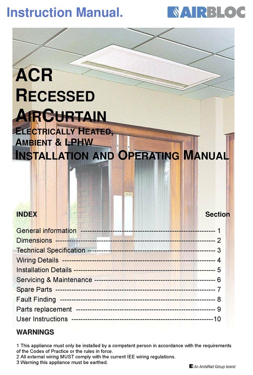
Airbloc AC Series User manual

Instruction Manual.
INDEX Section
General information ------------------------------------------------------------1
Dimensions -----------------------------------------------------------------------2
Technical Specification --------------------------------------------------------3
Wiring Details --------------------------------------------------------------------4
Installation Details --------------------------------------------------------------5
Option Light Box Installation -------------------------------------------------6
Option Luminaire Installation ------------------------------------------------7
Servicing & Maintenance -----------------------------------------------------8
Spare Parts -----------------------------------------------------------------------9
Fault Finding ------------------------------------------------------------------ 10
Parts replacement ------------------------------------------------------------ 11
User Instructions --------------------------------------------------------------12
AC COMMERCIAL & RETAIL
ELECTRICALLY HEATED, AMBIENT & LPHW
INSTALLATION AND OPERATING
MANUAL
WARNINGS
1 This appliance must only be installed by a competent person in accordance with the
requirements of the Codes of Practice or the rules in force.
2 All external wiring MUST comply with the current IEE wiring regulations.
3 Warning this appliance must be earthed.

2
Document Index.
1 Installation Requirements
1.1 Introduction
1.2 General
1.3 Electrical Supply
1.4 Location
1.5 Clearance Distance
1.6 Health and Safety
1.7 Standards
2 Dimensions
2.1 AC Air Curtain
2.2 Switchbox
2.2.1 Heated Switchbox
2.2.2 Ambient Switchbox
2.3 Optional SmartElec Controller
2.4 SmartElec Base Unit
3 Technical Specifications
3.1 Electrical Heated, Std Capacity 6kW
3.2 Electrical Heated, Std Capacity 9-18kW
3.3 Electrical Heated, High Capacity 12-24kW
3.4 Ambient, Std Capacity
3.5 Ambient, High Capacity
3.6 LPHW, Std Capacity
3.7 LPHW, High Capacity
3.8 SmartElec Controller
4 Wiring Diagrams
4.1 Electrical Heated, Std Capacity 6kW
4.2 Electrical Heated, Std Capacity 9-18kW
4.3 Electrical Heated, High Capacity 12-24kW
4.4 Ambient/LPHW, Std Capacity
4.5 Ambient/LPHW, High Capacity
4.6 Multi Electrical Heated via Slave
4.7 Multi Ambient/LPHW via Slave
4.8 Electrical Heated via External Switching
4.9 Electrical Heated via Room Stat -On/Off
4.10 Electrical Heated via Room Stat - 2 Stage
4.11 Ambient/LPHW via External Switching
4.12 Installer Wiring SmartElec Controller
4.13 Factory Wiring SmartElec Controller
4.14 Network Wiring SmartElec Controller
5 Installation Requirements
5.1 Mounting
5.2 Electrical Supply
5.3 Installation
5.4 Electrical Connections
5.5 Option SmartElec Controller
5.6 LPHW only
6 Optional Light Box/Down Lighters
6.1 Dimensions
6.2 Installation
6.3 Wiring
6.4 Rear Panel & Sign Options
7 Optional Fire Exit Luminaries
7.1 General
7.2 Remote Switching
7.3 Commissioning/Testing
7.4 Specification
7.4.1 Non-maintained
7.4.2 Maintained
7.5 Installation
7.6 Wiring Diagram
8 Servicing & Maintenance Instructions
9 Spare Parts
10 Fault Finding Guide
10.1 General
10.2 Electrical Heated
10.3 Optional SmartElec Controller
10.3.1 Fault Code chart
10.3.2 LED indication
11 Replacing Parts
11.1 Rotor and Motor
11.2 Electrical Element
12 User and Operating Instructions
12.1 Electrically Heated
12.1.1 Switchbox Operation
12.1.2 Turning Off
12.2 Ambient/LPHW
12.2.1 Switchbox Operation
12.2.2 Turning Off
12.3 Optional SmartElec Controller
12.3.1 Keypad
12.3.2 Operation
12.3.3 Network Addressing

3
1.1 Introduction
This instruction manual describes the Airbloc AC
Commercial & Retail range of air curtains.
Models range from 1000mm to 2000mm in length,
in both Standard and High capacity and are
available in either Electrically heated, Ambient or
LPHW. They are designed for mounting above or
slung on drop rods above doorways.
Each air curtain is supplied with a selectable
switchbox for two fan speeds (Ambient/LPHW) or
two fan and two heat settings (Electrically heated).
Alternatively an optional SmartElec control system
consists of a base unit (installed within the air
curtain) and a program panel that can be installed
remote from the air curtain. Usually, the program
panel is mounted at a low level from the air curtain
for user access and to a maximum distance of
50m. The base unit and program panel are linked
by low voltage cable as specified in these
instructions. The factory fitted base unit shown
above provides terminals for 3 phase supply
connection and the low voltage program panel
wires. The SmartElec base unit rapidly pulses
energy to the heating elements. This combined
with the inbuilt intelligent sensor control,
maintains a fixed outlet temperature, thereby
reducing energy consumption as compared to
an air curtain without the SmartElec control. The
program panel shown above allows the user to
control either a single air curtain, or a network of
up to 16 air curtains, & provides the following
functions:-
- Heat On or Off
- Off or Low, Medium and High Fan Speeds
- Air Outlet Temperature.
For further details please refer to section 12.3.
1.2 General
All installations must be in accordance with the
regulations in force in the country of use.
These instructions must be handed to the user on
completion of the installation.
Installers and service engineers must be able to
demonstrate competence and be suitably qualified
in accordance with the regulations in force in the
country of use.
To ensure continued and safe operation it is
recommended that the appliance is serviced
annually.
The manufacturer, offers a maintenance service.
Details are available on request.
The air curtain outlet grille and case air inlet slots
must not be obstructed during use.
1.3 Electrical Supply
It is recommended that the electrical supply to the
air curtain is via an appropriate switched fused
double pole isolator having a contact separation of
greater than 3mm.
For full electrical loadings, please refer to the
individual technical data sheets within this manual.
BMS control, time switches, room thermostats and
door interlocks can be installed at the discretion
and responsibility of the installer.
It is recommended that the electrical supply to the
SmartElec base unit is via an appropriate
switched isolator in accordance with the
regulations in force in the country of use and must
be via a fused isolator having a contact separation
of greater than 3mm in all poles.
Electrically heated supply is 415V 3 phase, neutral
and earth. Max cable inlet size is 6mm².
Remote unit is wired to the base unit via 2 pairs
24V Belden 8132 cable (or direct equiv).
Networked air curtain interconnects via 2 pairs
24V Belden 8132 cable (or direct eqiv).
Warning
For safety reasons a good earth connection must
ALWAYS be made to the heater and control box.
All unit must be wired in accordance with I.E.E
regulations for the Electrical Equipment of
Buildings and the installer should ensure that a
suitable isolating switch is connected in the mains
supply.
1.4 Location
Airbloc units should be installed horizontally
directly over the door opening. It is recommended
that the air curtain is installed on the inside of the
building, within the open room space against a
wall or ceiling. ACZ units are designed to be
positioned in suspended ceilings or bulkheads.
Care must be taken to allow complete free air
movement into the inlet grilles of the unit to ensure
correct working operation of the air curtain. The
discharge opening should be as close to the top of
the door as possible and to cover the entire door
width.
General Information

4
Units can be mounted adjacent to each other to
cover the full door opening across wider
entrances. Due to the in-built safety function of the
motor, a switching slave panel must be used if
using a singular switchbox.
These units are designed for surface mounting
and should not be placed into a ceiling void, due
to possible obstruction of airflow and difficulty in
routine cleaning and maintenance.
1.5 Clearance distances
It is recommended that a minimum clearance of
300mm is allowed around the top and front of the
unit. The clearance allows for cable entry and
prevents combustible surfaces overheating.
The minimum mounting height (floor to grille
outlet) is 1.8m. The recommended mounting
height is 3m for standard and 4m for high capacity
models.
1.6 Health and Safety.
Sole liability rests with the installer to ensure that
all site safety procedures are adhered to during
installation.
Sole liability rests with the installer to ensure that
protective safety wear such as hand, eye, ear and
head protection is used during installation of the
product.
Do not rest anything especially ladders against the
product.
1.7 Standards
Units conform to the European electrical standard
BS EN 60335-2-30:1997 and to the following
European CE directives. 73/23/EEC low voltage;
89/336/EEC and 98/68/EEC electromagnetic
compatibility.
SIDE VIEW
65
395
350
300
119
TOP VIEW A (see table) SUSPENSION POINTS
REAR VIEW B (see table) WALL FIXING POINTS
240crs 75
FRONT VIEW C (see table) DUCT OUTLET
D (see table) OVERALL WIDTH
mm 1000 1500 2000
A1062 1562 2062
B992 1492 1992
C1053 1553 2053
D1138 1638 2138
2. Dimensions.
2.1 AC Air Curtain

5
2.1 ACZ Air Curtain
B (see table) WALL FIXING POINTS
TOP VIEW A (see table) SUSPENSION POINTS
FRONT VIEW D (see table) OVERALL WIDTH
D (see table) DUCT OUTLET
BOTTOM VIEW
300
71240 crs
357
66
SIDE VIEW
MAX - 563mm
MIN - 502mm
mm 1000 1500 2000
A1062 1562 2062
B992 1492 1992
C1053 1553 2053
D1138 1638 2138
2.2 Switchbox dimensions
2.2.1 Heated switchbox
FAN SPEED
ON/I
LIVE
PANEL
146.0
III
HEAT SETTING
III I
ENERGY SAVING AIR CURTAINS
AIRBLOC
86.0
120.6 crs
FAN SPEED
ON/ I
LIVE
PANEL
86.0
III
ENERGY SAVING AIR CURTAINS
AIRBLOC
86.0
61.0 crs
2.2.2 Ambient switchbox

6
146
146
38
12
45
80 crs 33
3380 crs
4 HolesØ5mm
Earthing
point Cable
Entry
Fig.2. Alternative conduit box
MK part no. 893ALM (or similar)
fig.1. Dimensions — Program Panel (surface
mount shown—factory supplied).
2.3 Optional SmartElec Controller dimensions
2.4 Optional SmartElec Base unit
(fitted in Air Curtain as option)
233.7
100
100

7
3.1 AC1000SE6* AC1500SE6*
General Data
Maximum height M3.0
Door width M1.0 1.5
Heat medium Electric heated
Maximum heat capacity kW 66
Heat setting 2
Heat setting kW 3 / 6 3 / 6
Fan type Crossflow
Fan dia mm 150
Fan settings 2
Air outlet Adjustable vent
Switching type Remote switchbox / SmartElec
Weight kg 39.5 49.0
Electrical Data
Maximum heat capacity kW 66
Supply voltage 230V 1ph 50Hz
Total load Amps 26.8
Starting Current Low speed amps Amps xxxx
High speed amps Amps xxxx
Running current Low speed amps Amps xxxx
High speed amps Amps xxxx
Cable size 3 x 4.0mm² + E
External fuse size amps Amps
Motor power W190
** Switch box pt. no. ASCP1-4
Switch box wiring 6 x 1.0mm² + Earth
Mains terminal block position Front right of centre - terminals N; L1; L2 & L3
Control terminal block position Front right of centre – terminals 1 - 6
** SmartElec Energy Saving Control pt. no. 102609
SmartElec Energy Saving Control wiring 2 x pair Belden 8132 (or similar)
Mains terminal block position SmartElec Base Unit - terminals N; L1; L2 & L3
Control terminal block position SmartElec Base Unit - terminals A; B; 0V & 7V
Air Data
Fan setting 2
Air volume Low speed m³/h 1300 1600
High speed m³/h 1850 2400
Air velocity Low @ 0M m/s 6
High @ 0M m/s 8.5
High @ 1M m/s 4.5
High @ 2M m/s 2.9
High @ 3M m/s 2.1
Delta T Low speed °C 35 31 28
High speed °C 25 23 21
Noise level @ 3M Free field Low speed dBA 50
High speed dBA 55
Dims Data
Length mm 1138 1638
Depth (width) mm 350
Height including outlet mm 395
Outlet length mm 1095 1595
Outlet depth mm 65
Outlet height mm Flush
Drop rod mounting rear to centres on depth mm 119
Drop rod side to 1st Centre mm 38
Drop rod mounting centres on length mm 1062 1562
Wall mounting side to 1st centre mm 73
Wall mounting top to 1st centre mm 75
Wall mounting centres on length mm 992 1492
Wall mounting centres on height mm 240
32
3. Technical Specification.
* Suffix with S for metallic silver finish and W for white RAL9010 finish.
**Suffix with –SM for SmartElec Energy Saving Control.

8
3.2 AC1000SE9* AC1500SE12* AC2000SE18*
General Data
Maximum height M3.0
Door width M1.0 1.5 2.0
Heat medium Electric heated
Maximum heat capacity kW 912 18
Heat setting 2
Heat setting kW 4.5 / 9 6 / 12 9 / 18
Fan type Crossflow
Fan dia mm 150
Fan settings 2
Air outlet Adjustable vent
Switching type Remote switchbox / SmartElec
Weight kg 39.5 49.0 60.0
Electrical Data
Maximum heat capacity kW 912 18
Supply voltage 415V 3ph 50Hz
Total load amps 14.2 18.2 26.7
Starting Current Low speed amps A/pha 13.9 18.2 26.3
High speed amps A/pha 14.2 18.2 26.7
Running current Low speed amps A/pha 13.3 17.7 26.2
High speed amps A/pha 13.4 17.7 26.3
Cable size 4 x 2.5mm² + E 4 x 4.0mm² + Earth
External fuse size amps A/pha 14.2 18.2 26.7
Motor power W190
** Switch box pt.
no. ASCP1-4
Switch box wiring 6 x 1.0mm² + Earth
Mains terminal block position Front right of centre - terminals N; L1; L2 & L3
Control terminal block position Front right of centre – terminals 1 - 6
** SmartElec Energy Saving Control pt.
no. 102609
SmartElec Energy Saving Control wiring 2 x pair Belden 8132 (or similar)
Mains terminal block position SmartElec Base Unit - terminals N; L1; L2 & L3
Control terminal block position SmartElec Base Unit - terminals A; B; 0V & 7V
Air Data
Fan setting 2
Air volume Low speed m³/h 1300 1600 2900
High speed m³/h 1850 2400 4100
Air velocity Low @ 0M m/s 6
High @ 0M m/s 8.5
High @ 1M m/s 4.5
High @ 2M m/s 2.9
High @ 3M m/s 2.1
Delta T Low speed °C 35 31 28
High speed °C 25 23 21
Noise level @ 3M Free field Low speed dBA 50
High speed dBA 55
Dims Data
Length mm 1138 1638 2138
Depth (width) mm 350
Height including outlet mm 395
Outlet length mm 1095 1595 2095
Outlet depth mm 65
Outlet height mm Flush
Drop rod mounting rear to centres on depth mm 119
Drop rod side to 1st Centre mm 38
Drop rod mounting centres on length mm 1062 1562 2062
Wall mounting side to 1st centre mm 73
Wall mounting top to 1st centre mm 75
Wall mounting centres on length mm 992 1492 1992
Wall mounting centres on height mm 240
* Suffix with S for metallic silver finish and W for white RAL9010 finish.
**Suffix with –SM for SmartElec Energy Saving Control.

9
3.3 AC1000HE12* AC1500HE18* AC2000HE24*
General Data
Maximum height M4.0
Door width M1.0 1.5 2.0
Heat medium Electric heated
Maximum heat capacity kW 12 18 24
Heat setting 2
Heat setting kW 6 / 12 9 / 18 12 / 24
Fan type Crossflow
Fan dia mm 150
Fan settings 2
Air outlet Adjustable vent
Switching type Remote switchbox / SmartElec
Weight kg 39.5 49.0 60.0
Electrical Data
Maximum heat capacity kW 12 18 24
Supply voltage 415V 3ph 50Hz
Total load amps 18.5 29.5 38.4
Starting Current Low speed amps A/pha 17.9 26.8 24.6
High speed amps A/pha 18.5 29.5 38.4
Running current Low speed amps A/pha 17.4 25.6 34.5
High speed amps A/pha 17.8 26.6 35.4
Cable size 4 x 4.0mm² + E 4 x 6.0mm² + Earth
External fuse size amps A/pha 18.5 29.5 38.4
Mains terminal block position Front right of centre
Motor power W190
** Switch box pt.
no. ASCP1-4
Switch box wiring 6 x 1.0mm² + Earth
Mains terminal block position Front right of centre - terminals N; L1; L2 & L3
Control terminal block position Front right of centre – terminals 1 - 6
** SmartElec Energy Saving Control pt.
no. 102609
SmartElec Energy Saving Control wiring 2 x pair Belden 8132 (or similar)
Mains terminal block position SmartElec Base Unit - terminals N; L1; L2 & L3
Control terminal block position SmartElec Base Unit - terminals A; B; 0V & 7V
Air Data
Fan setting 2
Air volume Low speed m³/h 1850 2400 4100
High speed m³/h 2300 3300 5000
Air velocity Low @ 0M m/s 8.5
High @ 0M m/s 11.0
High @ 1M m/s 5.4 5.5 5.2
High @ 2M m/s 3.6 3.7 3.6
High @ 3M m/s 2.6 2.5 2.4
High @ 4M m/s 1.5 1.6 1.4
Delta T Low speed °C 33 29 27
High speed °C 26 23 20
Noise level @ 3M Free field Low speed dBA 55
High speed dBA 60
Dims Data
Length mm 1138 1638 2138
Depth (width) mm 350
Height including outlet mm 395
Outlet length mm 1095 1595 2095
Outlet depth mm 65
Outlet height mm Flush
Drop rod mounting rear to centres on depth mm 119
Drop rod side to 1st Centre mm 38
Drop rod mounting centres on length mm 1062 1562 2062
Wall mounting side to 1st centre mm 73
Wall mounting top to 1st centre mm 75
Wall mounting centres on length mm 992 1492 1992
Wall mounting centres on height mm 240
* Suffix with S for metallic silver finish and W for white RAL9010 finish.
**Suffix with –SM for SmartElec Energy Saving Control.

10
3.4 AC1000SA* AC1500SA* AC2000SA*
General Data
Maximum height M3.0
Door width M1.0 1.5 2.0
Heat medium Ambient
Fan type Crossflow
Fan dia mm 150
Fan settings 2
Air outlet Adjustable vent
Switching type Remote switchbox
Weight kg 39.5 49.0 60.0
Electrical Data
Supply voltage 230V 1ph 50Hz
Total load amps 2.5
Starting Current Low speed amps A/pha 2.6
High speed amps A/pha 3.1
Running current Low speed amps A/pha 2.5
High speed amps A/pha 1.8
Cable size 2 x 0.75mm² + Earth
External fuse size amps A/pha 10
Motor power W190
Switch box pt.
no. ASCP1-2
Switch box wiring 4 x 0.75mm² + Earth
Mains terminal block position Front right of centre - terminals N; L & E
Control terminal block position Front right of centre – terminals 1 & 2
Air Data
Fan setting 2
Air volume Low speed m³/h 1300 1600 2900
High speed m³/h 1850 2400 4100
Air velocity Low @ 0M m/s 6
High @ 0M m/s 8.5
High @ 1M m/s 4.5
High @ 2M m/s 2.9
High @ 3M m/s 2.1
Noise level @ 3M Free field Low speed dBA 50
High speed dBA 55
Dims Data
Length mm 1138 1638 2138
Depth (width) mm 350
Height including outlet mm 395
Outlet length mm 1095 1595 2095
Outlet depth mm 65
Outlet height mm Flush
Drop rod mounting rear to centres on depth mm 119
Drop rod side to 1st Centre mm 38
Drop rod mounting centres on length mm 1062 1562 2062
Wall mounting side to 1st centre mm 73
Wall mounting top to 1st centre mm 75
Wall mounting centres on length mm 992 1492 1992
Wall mounting centres on height mm 240

11
3.5 AC1000HA* AC1500HA* AC2000HA*
General Data
Maximum height M4.0
Door width M1.0 1.5 2.0
Heat medium Ambient
Fan type Crossflow
Fan dia mm 150
Fan settings 2
Air outlet Adjustable vent
Switching type Remote switchbox
Weight kg 39.5 49.0 60.0
Electrical Data
Maximum heat capacity kW 12 18 24
Supply voltage 230V 1ph 50Hz
Total load amps 2.5
Starting Current Low speed amps A/pha 2.6
High speed amps A/pha 3.1
Running current Low speed amps A/pha 2.5
High speed amps A/pha 1.8
Cable size 2 x 0.75mm² + Earth
External fuse size amps A/pha 10
Mains terminal block position Front right of centre
Motor power W190
Switch box pt.
no. ASCP1-2
Switch box wiring 4 x 0.75mm² + Earth
Mains terminal block position Front right of centre - terminals N; L & E
Control terminal block position Front right of centre – terminals 1 - 2
Air Data
Fan setting 2
Air volume Low speed m³/h 1850 2400 4100
High speed m³/h 2300 3300 5000
Air velocity Low @ 0M m/s 8.5
High @ 0M m/s 11.0
High @ 1M m/s 5.4 5.5 5.2
High @ 2M m/s 3.6 3.7 3.6
High @ 3M m/s 2.6 2.5 2.4
High @ 4M m/s 1.5 1.6 1.4
Delta T Low speed °C 33 29 27
High speed °C 26 23 20
Noise level @ 3M Free field Low speed dBA 55
High speed dBA 60
Dims Data
Length mm 1138 1638 2138
Depth (width) mm 350
Height including outlet mm 395
Outlet length mm 1095 1595 2095
Outlet depth mm 65
Outlet height mm Flush
Drop rod mounting rear to centres on depth mm 119
Drop rod side to 1st Centre mm 38
Drop rod mounting centres on length mm 1062 1562 2062
Wall mounting side to 1st centre mm 73
Wall mounting top to 1st centre mm 75
Wall mounting centres on length mm 992 1492 1992
Wall mounting centres on height mm 240

12
3.6 AC1000SW9* AC1500SW12* AC2000SW18*
General Data
Maximum height M3.0
Door width M1.0 1.5 2.0
Heat medium LPHW
Maximum heat capacity kW 912 18
Heat setting 1
Heat setting kW 912 18
Fan type Crossflow
Fan dia mm 150
Fan settings 2
Air outlet Adjustable vent
Switching type Remote switchbox
Weight kg 39.5 49.0 60.0
Electrical Data
Maximum heat capacity kW 912 18
Supply voltage 230V 1ph 50Hz
Total load amps 2.5
Starting Current Low speed amps A/pha 2.6
High speed amps A/pha 3.1
Running current Low speed amps A/pha 2.5
High speed amps A/pha 1.8
Cable size 2 x 0.75mm² + Earth
External fuse size amps A/pha 10
Motor power W190
Switch box pt.
no. ASCP1-2
Switch box wiring 4 x 0.75mm² + Earth
Mains terminal block position Front right of centre - terminals N; L & E
Control terminal block position Front right of centre – terminals 1 & 2
Air Data
Fan setting 2
Air volume Low speed m³/h 1300 1600 2900
High speed m³/h 1850 2400 4100
Air velocity Low @ 0M m/s 6
High @ 0M m/s 8.5
High @ 1M m/s 4.5
High @ 2M m/s 2.9
High @ 3M m/s 2.1
Delta T Low speed °C 35 31 28
High speed °C 25 23 21
Noise level @ 3M Free field Low speed dBA 50
High speed dBA 55
LPHW Data
LPHW flow l/s 0.20 0.27 0.40
Fluid pressure drop kPA 23.0 15.0
Flow & return connection mm 15
Inlet temp °C 82
Outlet temp °C 71
Dims Data
Length mm 1138 1638 2138
Depth (width) mm 350
Height including outlet mm 395
Outlet length mm 1095 1595 2095
Outlet depth mm 65
Outlet height mm Flush
Drop rod mounting rear to centres on depth mm 119
Drop rod side to 1st Centre mm 38
Drop rod mounting centres on length mm 1062 1562 2062
Wall mounting side to 1st centre mm 73
Wall mounting top to 1st centre mm 75
Wall mounting centres on length mm 992 1492 1992
Wall mounting centres on height mm 240

13
3.7 AC1000HW12* AC1500HW18* AC2000HW24*
General Data
Maximum height M4.0
Door width M1.0 1.5 2.0
Heat medium LPHW
Maximum heat capacity kW 12 18 24
Heat setting 1
Heat setting kW 12 18 24
Fan type Crossflow
Fan dia mm 150
Fan settings 2
Air outlet Adjustable vent
Switching type Remote switchbox
Weight kg 39.5 49.0 60.0
Electrical Data
Maximum heat capacity kW 12 18 24
Supply voltage 230V 1ph 50Hz
Total load amps 2.5
Starting Current Low speed amps A/pha 2.6
High speed amps A/pha 3.1
Running current Low speed amps A/pha 2.5
High speed amps A/pha 1.8
Cable size 2 x 0.75mm² + Earth
External fuse size amps A/pha 10
Mains terminal block position Front right of centre
Motor power W190
Switch box pt.
no. ASCP1-2
Switch box wiring 4 X 0.75mm² + Earth
Mains terminal block position Front right of centre - terminals N; L & E
Control terminal block position Front right of centre – terminals 1 & 2
Air Data
Fan setting 2
Air volume Low speed m³/h 1850 2400 4100
High speed m³/h 2300 3300 5000
Air velocity Low @ 0M m/s 8.5
High @ 0M m/s 11.0
High @ 1M m/s 5.4 5.5 5.2
High @ 2M m/s 3.55 3.7 3.6
High @ 3M m/s 2.6 2.5 2.4
High @ 4M m/s 1.5 1.6 1.4
Delta T Low speed °C 33 29 27
High speed °C 26 23 20
Noise level @ 3M Free field Low speed dBA 55
High speed dBA 60
LPHW Data
LPHW flow l/s 0.27 0.40 0.53
Fluid pressure drop kPA 19 23 24
Flow & return connection mm 15
Inlet temp °C 82
Outlet temp °C 71
Dims Data
Length mm 1138 1638 2138
Depth (width) mm 350
Height including outlet mm 395
Outlet length mm 1095 1595 2095
Outlet depth mm 65
Outlet height mm Flush
Drop rod mounting rear to centres on depth mm 119
Drop rod side to 1st Centre mm 38
Drop rod mounting centres on length mm 1062 1562 2062
Wall mounting side to 1st centre mm 73
Wall mounting top to 1st centre mm 75
Wall mounting centres on length mm 992 1492 1992
Wall mounting centres on height mm 240

14
3.8 SmartElec
General Data
Sensor input NTC
Control Setpoint 16 to 35 ºC in steps of 1 degree
Temperature Control Proportional with 1ºC hysteresis
Minimum Power 30% to 99 %
Cycle time 0.3 seconds fixed
Protection 2 x high speed fuse for the protection of the heater switching devices
Fan Output 3 off Relay for High, Medium and Low Fan setting 3A max 240Vac
Connection Screw terminals 4 for supply, 3 for heater output, 4 for fan output, 2 for
sensor input, 2 for external thermal trip
Supply 415 Vrms +/-15% 50/60Hz 5VA max.
Dimensions Program panel 101mm(L) x 101mm(W) x 60mm(H) max.
Mounting positions Program panel fixing centres 80mm x 80mm
Temperature 0 to 50 ºC operating; -20 to 65 ºC storage
Display Three 7-segment LCD red for parameter display
Push buttons 3 positive feedback tactile push buttons

15
4. Wiring Diagrams.
T1
L1 L3
L2
AC2
A1
T3
T2 A2
M
M3
M2 M1
M4
T1
L1 A1
L3
L2
AC1
T3
T2 A2
cut-out
Ther mal
Th1
7654
3
4
43
12
F1
5
N
N
321
5A
F1 E
N
L1
L3
NL2L1
230V1N~
Heating
Elements
900367
Swit chbox
Installer connections
Internal wiring
Heating
El ement s
4.1 Wiring diagram Electrically Heated AC1000SE6 and AC1500SE6

16
4.2 Wiring diagram Electrically Heated AC1000SE9; AC1500SE12 and AC2000SE18
AC2-T3
T1
L1 L3
L2
AC2
A1
T3
T2
AC2-T2
AC2-T1
A2
M
M3
M2 M1
M4
T1
L1
AC1-T3
A1
L3
L2
AC1
T3
T2 A2
cut-out
Ther mal
Th1
AC1-T1
AC1-T2
7654
3
4
43
12
F1
5
N
N
321
5A
F1 E
N
AC1-L3
AC2-L3
AC1-L2
AC2-L1
AC2-L2
AC1-L1
L1
L3
NL2L1
380-415V3N~
El ect r i cal
Elements
900092r2
El ect r i cal
El ement s
Swit chbox
Installer connections
Internal wiring

17
4.3 Wiring diagram Electrically Heated AC1000HE12; AC1500HE18 and AC2000HE24
AC2-T3
T1
L1 L3
L2
AC2
A1
T3
T2
AC2-T2
AC2-T1
A2
M
M3
M2 M1
M4
T1
L1
AC1-T3
A1
L3
L2
AC1
T3
T2 A2
cut-out
Ther mal
Th1
AC1-T1
AC1-T2
7654
3
4
43
12
F1
5
N
N
321
5A
F1 E
N
AC1- L3
AC2- L3
AC1- L2
AC2- L1
AC2- L2
AC1- L1
L1
L3
NL2L1
380-415V3N~
El ect r i cal
El ement s
900270r1
El ect r i cal
El ement s
Swit chbox
Installer connections
Internal wiring

18
4.4 Wiring diagram LPHW AC1000SW09; AC1500SW12, AC2000SW18, plus Ambient
AC1000SA, AC1500SA and AC2000SA
900305
5A
M3 M1
M2
M4
M
NE
L
230V1Ph
2
F1
1
3
N
Installer connections
Internal wiring
Swi t chbox

19
4.5 Wiring diagram LPHW AC1000HW12; AC1500HW18, AC2000HW24 plus Ambient
AC1000HA, AC1500HA and AC2000HA
900220r1
5A
M3 M1
M2
M4
M
NE
L
230V1Ph
2
F1
1
3
N
Installer connections
Internal wiring
Swi t chbox

20
4.6 Typical wiring diagram Multi AC heated air curtains via Slave panel (supplied by others)
L2
COM
Switchbox shown rear view
COM COM
L1 L2 L1 L2 L1
COM
L1 L2
From terminal 'F1'
aircurtains 2,3 &4
}
}
To 'low fan speed'
aircurtains 2,3 &4
b
c
d
a
}
To 'hi fan speed'
aircurtains 2,3 &4
a
d
c
b
}
To 'low heat'
aircurtains 2,3 &4
a
d
c
b
}
To 'hi heat'
aircurtains 2,3 &4
b
c
d
a
Slave Box
6725
4
3
N
L3
L2 ENF1 1
NN
5A
Aircurtain 1 (AC HE shown)
L1 L1
415V 3Pha
50Hz
Supply
}
This manual suits for next models
21
Table of contents
Other Airbloc Heater manuals
Popular Heater manuals by other brands

Svan
Svan SVCA2000MIR instruction manual

Tecnosystemi
Tecnosystemi Apply air ARIA 4 INNOVATION Installation and user manual

Kingfer Industrial
Kingfer Industrial Blue Flame KF-B006-TP user manual

Beper
Beper P203TER001 Use instruction

Rowi
Rowi HWH 2000/2/1 D Convection operating instructions

DeLonghi
DeLonghi Electric oil filled radiator instructions