Johnson Controls LSWU User guide

WATER-COOLED SELF-CONTAINED UNITS
MODEL LSWU / LSWD / LSWF
WITH IPU2 CONTROL
025-105 TONS
INDOOR PACKAGED EQUIPMENT
START-UP GUIDE Supersedes 145.05-SU7 (412) Form 145.05-SU7 (1019)
035-22911-000
Issue Date:
October 31, 2019

JOHNSON CONTROLS
2
FORM 145.05-SU7
ISSUE DATE: 10/31/2019
This equipment is a relatively complicated apparatus.
During installation, operation maintenance or service,
individuals may be exposed to certain components or
conditions including, but not limited to: refrigerants,
materials under pressure, rotating components, and
both high and low voltage. Each of these items has the
potential, if misused or handled improperly, to cause
bodily injury or death. It is the obligation and respon-
sibility of operating/service personnel to identify and
recognize these inherent hazards, protect themselves,
and proceed safely in completing their tasks. Failure
to comply with any of these requirements could result
in serious damage to the equipment and the property in
IMPORTANT!
READ BEFORE PROCEEDING!
GENERAL SAFETY GUIDELINES
which it is situated, as well as severe personal injury or
death to themselves and people at the site.
This document is intended for use by owner-authorized
operating/service personnel. It is expected that these
individuals possess independent training that enable
them to perform their assigned tasks properly and safe-
ly. It is essential that, prior to performing any task on
this equipment, this individual shall have read and un-
derstood this document and any referenced materials.
This individual shall also be familiar with and comply
with all applicable governmental standards and regula-
tions pertaining to the task in question.
SAFETY SYMBOLS
The following symbols are used in this document to alert the reader to specific situations:
Indicates a possible hazardous situation
which result in death or serious injury if
proper care is not taken.
Indicates a potentially hazardous situa-
tion which result in possible injuries or
damage to equipment if proper care is
not taken.
Identies a hazard which could lead to
damage to the machine, damage to other
equipment and/or environmental pollu-
tion if proper care is not taken or instruc-
tions and are not followed.
Highlights additional information useful
to the technician in completing the work
being performed properly.
External wiring, unless specied as an optional connection in the manufacturer’s product line, is
not to be connected inside the control cabinet. Devices such as relays, switches, transducers and
controls and any external wiring must not be installed inside the micro panel. All wiring must be in
accordance with Johnson Controls’ published specications and must be performed only by a quali-
ed electrician. Johnson Controls NOT be responsible for damage/problems resulting from improper
connections to the controls or application of improper control signals. Failure to follow this warning
void the manufacturer’s warranty and cause serious damage to property or personal injury.

JOHNSON CONTROLS 3
FORM 145.05-SU7
ISSUE DATE: 10/31/2019
1 2 3 4 5 6 7 8 9 10 11 12 13 14 15 16 17 18 19 20 21 22 23 24 25 26 27 28 29 30 31
L S W U 0 9 5 S E A 4 6 S P D 4 0 O H 3 6 P 2 V V C O 0 0 0 S
LSWU(D/F) PRODUCT MODEL NUMBER
SUPPLY
VOLTAGE
17 = 208V-3-60
28 = 230V-3-60
46 = 460V-3-60
58 = 575V-3-60
POWER SUPPLY
CONNECTION
SPT = Single Point Terminal Block
SPD = Single Point Disconnect Switch
DPT = Dual Point Terminal Block
DPD = Dual Point Disconnect Switch
NOMINAL
CAPACITY
025 = 25 Ton
032 = 32 Ton
035 = 35 Ton
040 = 40 Ton
050 = 50 Ton
060 = 60 Ton
070 = 70 Ton
080 = 80 Ton
095 = 95 Ton
105 = 105 Ton
105 = 105 Ton
SUPPLY
MOTOR HP
05 = 5 HP
07 = 7.5 HP
10 = 10 HP
15 = 15 HP
20 = 20 HP
25 = 25 HP
30 = 30 HP
40 = 40 HP
50 = 50 HP
60 = 60 HP
SUPPLY
MOTOR TYPE
OH = ODP High Eff.
OP = ODP Premium Eff.
TH = TEFC High Eff.
TP = TEFC Premium Eff.
FAN SIZE
25 = 25 inch
28 = 28 inch
32 = 32 inch
36 = 36 inch
40 = 40 inch
FAN CLASS
P2 = CL2, Plenum
P3 = CL3, Plenum
VFD OPTION
CV = Constant Volume
VV = Variable Air Volume
VB = VAV with Bypass
VR = VFD Ready
HEAT OPTION
CO = Cooling Only
HW = Hot Water
ST = Steam Coil
EH = Electric Heat
ELECTRIC
HEAT SIZE
000 = No EH
017 = 17.5 KW
035 = 35 KW
052 = 52.5 KW
070 = 70 KW
105 = 105 KW
DESIGN SEQUENCE
A = Initial Design
UNIT TYPE
EVAPORATOR COIL
SE = Standard Efficiency
HE = High Efficiency
ENTERING WATER
TEMPERATURE
S = Standard Temperature
H = High Temperature
L = "L" Series
S = Self-Contained
W = Water Cooled
U/D/F = Upflow/Downflow/Frontflow
2R = CL2, Plenum
w/ Piezo Ring
CHANGEABILITY OF THIS DOCUMENT
In complying with Johnson Controls’ policy for con-
tinuous product improvement, the information con-
tained in this document is subject to change without
notice. Johnson Controls makes no commitment to
update or provide current information automatically to
the manual owner. Updated manuals, if applicable, can
be obtained by contacting the nearest Johnson Controls
Service office.
Operating/service personnel maintain responsibility for
the applicability of these documents to the equipment.
If there is any question regarding the applicability of
these documents, the technician should verify whether
the equipment has been modified and if current litera-
ture is available from the owner of the equipment prior
to performing any work on the equipment
CHANGE BARS
Revisions made to this document are indicated with a
line along the left or right hand column in the area the
revision was made. These revisions are to technical in-
formation and any other changes in spelling, grammar
or formatting are not included.

JOHNSON CONTROLS
4
FORM 145.05-SU7
ISSUE DATE: 10/31/2019
THIS PAGE INTENTIONALLY BLANK

JOHNSON CONTROLS 5
FORM 145.05-SU7
ISSUE DATE: 10/31/2019
TABLE OF CONTENTS
GENERAL SAFETY GUIDELINES...........................................................................................................................2
SAFETY SYMBOLS..................................................................................................................................................2
CHANGEABILITY OF THIS DOCUMENT................................................................................................................3
Change Bars ....................................................................................................................................................3
LIST OF FIGURES....................................................................................................................................................6
LIST OF TABLES......................................................................................................................................................6
SECTION 1 - USER INTERFACE ............................................................................................................................7
Password.......................................................................................................................................................... 7
Navigation ........................................................................................................................................................8
SECTION 2 - INTRODUCTION.................................................................................................................................9
SECTION 3 - PRE START-UP CHECKLIST........................................................................................................... 11
VFD Supply Fan (When Installed) .................................................................................................................21
Analog Input verification .................................................................................................................................22
Digital Input Verification..................................................................................................................................23
Factory Run Test Feature...............................................................................................................................24
Supply Fan Test for Constant Volume or VAV/Flexsys Units..........................................................................24
Water Flow Switch Test ..................................................................................................................................25
Compressor Run Test.....................................................................................................................................25
Damper Test (if available)...............................................................................................................................26
Manually Forcing Digital
and Analog Outputs........................................................................................................................................27
To Verify Electric Heat Operates Correctly: ....................................................................................................27
To Verify Heating Valve (Steam or Hot Water) Operation:..............................................................................27
To Verify Condenser Actuator/Valve Operation: .............................................................................................28
To Verify Economizer Actuator/Valve Operation: ............................................................................................28
Emergency Shutdown .................................................................................................................................... 28
Occupied Command....................................................................................................................................... 28
Alarm Outputs ................................................................................................................................................28
Pump Output .................................................................................................................................................. 28
VAV Heat ........................................................................................................................................................28
CTB1 Field Control Wiring (Inputs) ................................................................................................................ 29
SECTION 4 - POST START-UP DATA....................................................................................................................31
For technical assistance:................................................................................................................................33

JOHNSON CONTROLS
6
FORM 145.05-SU7
ISSUE DATE: 10/31/2019
LIST OF FIGURES
LIST OF TABLES
TABLE 1 - ABB VFD Configuration Parameters for L-Series WCSC......................................................................21
TABLE 2 - Analog Input Values...............................................................................................................................22
TABLE 3 - WCSC LED Status Indicators................................................................................................................23
TABLE 4 - Digital Input Verification chart ................................................................................................................23
TABLE 5 - Factory Run Tests..................................................................................................................................24
TABLE 6 - Digital Outputs .......................................................................................................................................27
TABLE 7 - Analog Outputs ......................................................................................................................................27
FIGURE 1 - User Interface Control Panel .................................................................................................................7
FIGURE 2 - Field Control Wiring - Inputs ................................................................................................................29

JOHNSON CONTROLS 7
FORM 145.05-SU7
ISSUE DATE: 10/31/2019
LD16445
FIGURE 1 - USER INTERFACE CONTROL PANEL
PASSWORD
Use passwords to restrict access to the modification of
certain parameters using the SETPOINT, PROGRAM,
or OPTIONS menu keys. Each parameter is associated
with a level of access. Each level of access is associ-
ated with a specific password. The access levels avail-
able are Level 1 or Level 2.
• If a parameter is tagged as Level 1, password 9675
must be entered in order to change the value.
• If a parameter is tagged as Level 2, password
9725 must be entered in order to change the val-
ue. Entering the Level 2 password also allow the
changing of a Level 1 parameter.
• The maine Rocke switch must be turned OFF in
order to change any parameter in the OPTIONS
key.
Pressing the SETPOINTS, PROGRAM, or OPTIONS
key take the user to the Login Prompt. When the user
is first presented with the Login Prompt, the password
field is blank. If you need to change Level 1 or Level 2
parameters, you must know the appropriate password.
At that point only the parameters changeable under
the specific password level is displayed. For example,
if the user presses the OPTIONS menu key, and then
enters a Level 1 password, the user is presented with
a list of option parameters that are tagged as Level 1.
Press the correct sequence of numerical keys (the 0 key
through the 9 key) to enter the password and press the
key. As digits are entered, asterisks are placed in the
password field. Once entered, the menu system com-
pares the password to a list of stored passwords. If the
entered password matches one of the stored passwords,
the user can access at the specified level, and the dis-
play shows the first applicable parameter of the menu
list, with the appropriate edit prompts. If the password
is not correct, the screen displays “Password Incor-
rect” for two seconds and reverts to the Login Prompt.
Pressing the key during password entry cancels the
password entry process and takes the user back to the
Login Prompt.
SECTION 1 - USER INTERFACE

JOHNSON CONTROLS
8
FORM 145.05-SU7
ISSUE DATE: 10/31/2019
SECTION 1 - USER INTERFACE
Once a password is accepted, re-entry of that pass-
word is not required until key activity is idle for fifteen
minutes. This ensures that the menu system reverts to
password protection within an acceptable timeout.
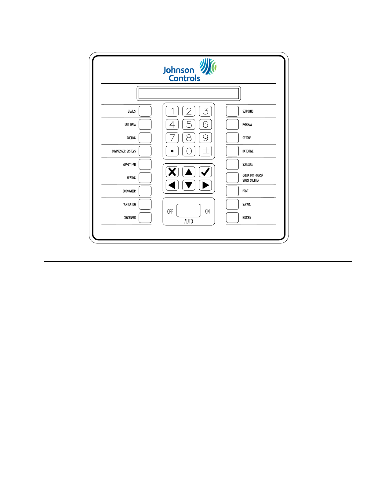
NAVIGATION
The keypad allows complete control of the system
from a central location. The keypad offers a multitude
of commands available to access displays, program pa-
rameters, and initiate system commands. The keypad
consists of thirty-six keys, which are divided into three
categories, Data Entry, Navigation, and Menu Selec-
tion keys. Each key is described in the sections below.
Data Entry Keys
Use the Data Entry Keys to enter values for items that
support edits. The keys available to support numeric
input are the 0 through 9 keys, the decimal key, the
+/- key, the key and the key. The keys available
to support choice input are the key, the key, the
key, and the key. Once editing has started, the
user must press either the key or the key. Any
other key press results in the “Press or to Exit”
message displayed for two seconds. If you try to edit
an item that is view only, it is ignored by the menu
system.
When a numeric value that can be modified is dis-
played under the “Setpoints” menu key, the Default,
High, and Low prompt is shown in the upper right por-
tion of the display. Pressing the +/- key, the decimal
key, or any of the 0 through 9 keys activate the edit
mode and a request for the proper password is made.
After the proper password is entered, the cursor is
shown at the digit to be changed. After the desired nu-
meric value is entered, press the key to save the new
value and exit the edit mode. Pressing the key fill
in the default value. Edits are only accepted when fol-
lowed by pressing the key. Pressing the key while
in the edit mode cancels the edit mode and leave the
value unchanged. If an out of range value is entered,
the Default, High and Low prompt is replaced by the
“Out of Range” message for two seconds.
When a choice value that can be modified is displayed
under the “Program” or “Options” menu key, the
prompt is shown to the left of the present choice.
The key or the key allow the different choices to
be viewed, and pressing either one activates the edit
mode and a request for the proper password made. See
Password section of this manual for the proper pro-
cedure for entering the password. When the desired
choice is displayed, press the key to save the new
value and exit the edit mode. Pressing the key while
in the edit mode cancels the edit mode and the value
is unchanged.
Navigation Keys
Use the Navigation Keys to browse items within a
menu. The keys currently available to support naviga-
tion are the Menu Select keys, the key, the key,
the key, and the key.
Menu Selection Keys
Pressing a Menu Select key brings the user to the first
screen under that menu. The screens within each menu
are arranged in a circular list. The user may browse
through the screens using the key and the key.
Pressing the key advances through the screens in
order from top to bottom until the bottom screen is
reached. When the bottom screen is displayed, press-
ing the key wraps the display to the top screen
of the menu. Pressing the key moves through the
screens in order from bottom to top until the top screen
is reached. When the top screen is displayed, press-
ing the key wraps the display to the bottom screen
of the menu. Once either the key or the key is
pressed, pressing any Menu Select key brings the user
to the first screen under that menu (even if it is the
same menu being viewed).
Navigation through the circular list of items is also
achieved by repeated presses of the same Menu Select
key, as long as no other keys are pressed. For exam-
ple, pressing the UNIT DATA key three times brings
the user to the third screen of the UNIT DATA menu;
pressing the UNIT DATA key once, then pressing the
key, then pressing the UNIT DATA key again brings
the user to the first screen of the UNIT DATA menu.
The key and the key are used to scroll “side-
ways” between the same displays for each system. For
example, when viewing the Sys 1 Pressures under the
COMPRESSOR SYSTEMS key, pressing the key
scrolls “sideways” to the Sys 2 Pressures display and
pressing the key scrolls “sideways” to the Sys Pres-
sures display for the last system on the unit.
When programming numeric or non-numeric values,
the key and the key are used to scroll forward
(down) and backward (up) through the items to be pro-
grammed or set.

JOHNSON CONTROLS 9
FORM 145.05-SU7
ISSUE DATE: 10/31/2019
This start-up guide indicates required field wiring,
connections, and programming to provide proper unit
operation. This guide does not include installation in-
formation. Refer to the Installation, Operation, and
Maintenance manual (Form 145.05-NOM7). Review
the IOM to ensure all proper procedures and safety
precautions are followed when starting this equipment.
Use the IOM as a reference if there are any questions
about the unit operation.
In addition, any system alarms indicated by the User
Interface should be diagnosed as referenced in the In-
stallation, Operation, and Maintenance manual - refer
to the Fault Description Table, located in the Service
section of that manual.
There are three different units that are manufactured
under this configuration: Constant Volume, Variable
Air Volume, and Flexsys Underfloor.
Constant Volume uses a standard supply air fan mo-
tor. Cooling/Heating operations are controlled by a
hardwired or communicated zone sensor. Once operat-
ing, supply air temperature is controlled to a supply air
temperature setpoint.
SECTION 2 - INTRODUCTION
Variable Air Volume uses a Variable Frequency Driven
supply air fan motor that controls the main supply duct
to a predetermined duct static setpoint. Cooling/Heat-
ing operations are determined by return air tempera-
ture control. Once operating, supply air temperature is
controlled to a supply air temperature setpoint.
Flexsys Underfloor systems use a Variable Frequency
Driven supply air fan motor that controls the main
supply duct or an underfloor cavity to a predetermined
duct static setpoint. Cooling/Heating operations are
determined by return air temperature control. Once
operating, supply air temperature is controlled to a
predetermined setpoint. There can be a bypass damper
installed that mixes return and supply air to a mixed air
setpoint in order to prevent overcooling the underfloor
space.
This start-up document guides a technician through the
control, mechanical, and sealed system of the unit to
complete a successful startup.

JOHNSON CONTROLS
10
FORM 145.05-SU7
ISSUE DATE: 10/31/2019
THIS PAGE INTENTIONALLY BLANK

JOHNSON CONTROLS 11
FORM 145.05-SU7
ISSUE DATE: 10/31/2019
SECTION 3 - PRE START-UP CHECKLIST

JOHNSON CONTROLS
12
FORM 145.05-SU7
ISSUE DATE: 10/31/2019
SECTION 3 - PRE START-UP CHECKLIST

JOHNSON CONTROLS 13
SECTION 3 - PRE START-UP CHECKLIST
FORM 145.05-SU7
ISSUE DATE: 10/31/2019

JOHNSON CONTROLS
14
FORM 145.05-SU7
ISSUE DATE: 10/31/2019
SECTION 3 - PRE START-UP CHECKLIST

JOHNSON CONTROLS 15
SECTION 3 - PRE START-UP CHECKLIST
FORM 145.05-SU7
ISSUE DATE: 10/31/2019

JOHNSON CONTROLS
16
FORM 145.05-SU7
ISSUE DATE: 10/31/2019
SECTION 3 - PRE START-UP CHECKLIST

JOHNSON CONTROLS 17
SECTION 3 - PRE START-UP CHECKLIST
FORM 145.05-SU7
ISSUE DATE: 10/31/2019

JOHNSON CONTROLS
18
FORM 145.05-SU7
ISSUE DATE: 10/31/2019
SECTION 3 - PRE START-UP CHECKLIST

JOHNSON CONTROLS 19
SECTION 3 - PRE START-UP CHECKLIST
FORM 145.05-SU7
ISSUE DATE: 10/31/2019

JOHNSON CONTROLS
20
FORM 145.05-SU7
ISSUE DATE: 10/31/2019
SECTION 3 - PRE START-UP CHECKLIST
Other manuals for LSWU
2
This manual suits for next models
2
Table of contents
Popular Water Dispenser manuals by other brands

GE
GE GXSS20H Owner's Manual & Installation Instructions

Haws
Haws HCR8 Nstallation, operation & maintenance instructions

Omnifilter
Omnifilter WH10 installation instructions

Puratech
Puratech PROFESSIONAL Series Owner's manual and installation guide

EcoWater
EcoWater ESD2700R25 owner's manual

Antunes
Antunes WSS-0948-R owner's manual

Everpure
Everpure In-line Filter IN-15 CR Specification sheet

WaterLogic
WaterLogic WL500 - Sparkling Installation procedures

Bunn
Bunn H5E Installation & operating guide

Elkay
Elkay DSBWCT1 Installation, care & use manual

Kenmore
Kenmore 625.34842 owner's manual

Miele professional
Miele professional PG 8597 operating instructions