Canature 785 User manual

785 Automatic Water Filters
MultiMedia
Neutralizing
Carbon
Nexsand
REVISION # 2
REVISION DATE 8/20/2014
#80150313
1. Read all instructions carefully before operation.
2. Avoid pinched o-rings during installation by applying (provided with install kit) N F certified
lubricant to all seals.
3. This system is not intended for treating water that is microbiologically unsafe or of unknown
quality without adequate disinfection before or after the system.
Canadian Head Office
655 Park St.
Regina, SK S4N 5N1
astern Sales & Distribution
20 Steckle Place, Unit 21
Kitchener ON N2E 2C3
U.S. Head Office
843 10th Avenue North
Golden Valley, MN 5542

2
Safety Guide
Check and comply with your provincial /
state and local codes. You must follow
these guidelines.
Use care when handling the filter tank. Do
not turn upside down, drop, drag or set on
sharp protrusions.
The system works on 1 volt-60 Hz electri-
cal power only. Be sure to use only the
included transformer.
Transformer must be plugged into an in-
door 1 0 volt, grounded outlet only.
WARNING: This system is not in-
tended for treating water that is microbio-
logically unsafe or of unknown quality
without adequate disinfection before or
after the system.
For your safety, the information in this manual must be followed to minimize the risk of
electric shock, property damage or personal injury.
Be sure to check the entire unit for any shipping damage or parts loss. Also note damage to
the shipping cartons. Contact the transportation company for all damage and loss claims.
The manufacturer is not responsible for damages in transit.
Small parts, needed to install the softener, are in a parts bag. To avoid loss of the small
parts, keep them in the parts bag until you are ready to use them.
Unpacking / Inspection
PAGE
Unpacking / Inspection 2
Safety Guide 2
Proper Installation 3
Specification
Before Starting Installation 5
Sizing Requirements 7
Installation Instructions 8
System Start Up 10
About The System 12
Maintenance 1
Main Repair Parts 16
Trouble Shooting 23
Warranty 2
Table of Contents

3
Proper Installation
This water filter system must be properly installed and located in accordance with the
Installation Instructions before it is used.
Do not
install or store where it will not be
exposed to temperatures below freezing or
exposed to any type of weather. Water
freezing in the system will break it. Do not
attempt to treat water over 1 °F.
Do not
install in direct sunlight. Excessive
sun or heat may cause distortion or other
damage to non-metallic parts.
Properly ground to conform with all gov-
erning codes and ordinances.
Use only
lead-free solder and flux
for all
sweat-solder connections, as required by
state and federal codes.
Maximum allowable inlet water pressure is
125 psi. If daytime pressure is over 8
psi, night time pressure may exceed the
maximum. Use a pressure reducing valve
to reduce the flow if necessary.
WARNING:
Discard all unused parts and
packaging material after installation. Small
parts remaining after the installation could
be a choke hazard.

4
Specifications
Continuous operation at flow rates greater than the ser-
vice flow rate may affect capacity and efficiency per-
formance.
The manufacturer reserves the right to make product
improvements which may deviate from the specifications
and descriptions stated herein, without obligation to
change previously manufactured products or to note the
change.
Peak flow rates are intended for intermittent use only
and are for residential application only
At the stated service flow rates, the pressure drop
through these devices will not exceed 5 psig
Service Flow Rates
Normal 4.0 gpm 5.0 gpm 7.0 gpm 10.0 gpm 12.0 gpm
Peak 5.0 gpm 7.0 gpm 10.0 gpm 12.0 gpm 15.0 gpm
Micron Rating 1520 micron 1520 micron 1520 micron 1520 micron 1520 micron
ackwash Flow Rate 4.0 gpm 5.0 gpm 7.0 gpm 10.0 gpm 14.0 gpm
Filter Media Volume Cubic Feet
0.75 ft
3
1.0 ft
3
1.5 ft
3
2.0 ft
3
3.0 ft
3
Filter Tank Size 8x44 9x48 10x54 12x52 14x65
Tank Jacket / Media Loaded Yes Yes Yes No No
Shipping Weight 79 lbs 118 lbs 144 lbs 198 lbs 342 lbs
Service Flow Rates
Normal 4.0 gpm 5.0 gpm 7.0 gpm 10 gpm 12.0 gpm
Peak 5.0 gpm 7.0 gpm 10.0 gpm 12.0 gpm 15.0 gpm
ackwash Flow Rate 3.5 gpm 4.0 gpm 5.0 gpm 7.0 gpm 10.0 gpm
Filter Media Volume Cubic Feet
0.75 ft
3
1.0 ft
3
1.5 ft
3
2.0 ft
3
3.0 ft
3
Filter Tank Size 8x44 9x48 10x54 12x52 14x65
Tank Jacket / Media Loaded Yes Yes Yes No No
Shipping Weight 50 lbs 60 lbs 78 lbs 95 lbs 138 lbs
Service Flow Rates
Normal 2.0 gpm 3.0 gpm 5.0 gpm 6.0 gpm 7.0 gpm
Peak 3.5 gpm 5.0 gpm 8.0 gpm 10.0 gpm 12.0 gpm
ackwash Flow Rate 3.5 gpm 4.0 gpm 5.0 gpm 7.0 gpm 10.0 gpm
Filter Media Volume Cubic Feet
0.75 ft
3
1.0 ft
3
1.5 ft
3
2.0 ft
3
3.0 ft
3
Filter Tank Size 8x44 9x48 10x54 12x52 14x65
Tank Jacket / Media Loaded Yes Yes Yes No No
Shipping Weight 93 lbs 120 lbs 164 lbs 207 lbs 330 lbs
Service Flow Rates
Normal 4.0 gpm 5.0 gpm 8.0 gpm 10.0 gpm
Peak 7.0 gpm 8.0 gpm 10.0 gpm 12 gpm
Micron Rating 35 micron 35 micron 35 micron 35 micron
ackwash Flow Rate 5.0 gpm 7.0 gpm 10.0 gpm 14.0 gpm
Filter Media Volume Cubic Feet
0.75 ft
3
1.0 ft
3
1.5 ft
3
2.0 ft
3
Filter Tank Size 8x44 9x48 10x54 12x52
Tank Jacket Yes Yes Yes No
Shipping Weight 90 lbs 135 lbs 205 lbs 255 lbs
ALL FILTERS
Plumbing Connections
Electrical Requirements
Water Temperature
Water Pressure
3/4" (Optional 1")
Input 120V 60 Hz Output 12V 650mA
Min 39 Max. 100 degrees Fahrenheit
Min. 20 Max. 125 psi
48NEX-75 585NEX-100 585NEX-150 585NEX-200
485NU-75 585NU-100 585NU-150 585NU-200 585NU-300
585TO-75 585TO-100 585TO-150 585TO-200 585TO-300
585MM-75 585MM-100 585MM-150 585MM-200 585MM-300
Specifications
Specifications
Specifications
Specifications

5
Taste & Odor Filter (Activated Carbon)
Unpleasant tastes and doors caused by chlo-
rine or organic substances, such as decayed
vegetation and run off, are absorbed by top
quality activated carbon. The filter will auto-
matically backwash to a predetermined
schedule. This frees the bed of accumulated
impurities and readies it for operation again.
Multi-Media Filter (Sediment)
Suspended particulate matter such as clay
and silt, which gives water a cloudy appear-
ance, is trapped in the filter bed to produce
clean, clear water. A variety of gravel and
sand facilitates more thorough backwashing
and prevents channeling. eriodic backwash-
ing cleans the bed.
Neutralizing Filter
The neutralizing filter contains blended media
which raises the pH of acidic water and neu-
tralizes its corrosive characteristics. In addi-
tion to protecting pipes, plumbing fixtures
and appliances, this filter also facilitates the
removal of iron and manganese by raising
the pH. This enables an iron filter to be used.
eriodic backwashing cleans the bed. Addi-
tional media may be required six months to
two years after installation, depending on the
water’s pH.
Before Starting Installation
Tools, ipe, and Fittings, Other Materials
liers
Screwdriver
Teflon tape
Razor knife
Two adjustable wrenches
Additional tools may be required if modifi-
cation to home plumbing is required.
lastic inlet and outlet fittings are included
with the filter. To maintain full valve flow,
3/4” or 1” pipes to and from the filter fit-
tings are recommended. You should main-
tain the same, or larger, pipe size as the
water supply pipe, up to the softener inlet
and outlet.
Use copper, brass, or EX pipe and fittings.
Some codes may also allow VC plastic
pipe.
ALWAYS install the included bypass valve,
or 3 shut-off valves. Bypass valves let you
turn off water to the filter for repairs if
needed, but still have water in the house
pipes.
5/8” OD drain line is needed for the valve
drain. A 10’ length of hose is included.
with some models.

6
Place the filter tank as close as possible to
the pressure tank (well system) or water
meter (city water).
Place the filter tank as close as possible to
a floor drain, or other acceptable drain
point (laundry tub, sump, standpipe, etc.).
Connect the filter to the main water supply
pipe BEFO E the water heater. DO NOT
RUN HOT WATER THROUGH THE FIL-
TER. Temperature of water passing
through the filter must be less than 100
deg. F.
Do not install the filter in a place where it
could freeze. Damage caused by freez-
ing is n t c vered by the warranty.
Put the filter in a place water damage is
least likely to occur if a leak develops. The
manufacturer will not repair or pay for wa-
ter damage.
A 120 volt electric outlet, to plug the in-
cluded transformer into, is needed within 6
feet of the filter. The transformer has an
attached 6 foot power cable. Be sure the
electric utlet and transf rmer are in
an inside l cati n, t pr tect fr m
wet weather.
If installing in an outside location, you
must take the steps necessary to assure
the filter, installation plumbing, wiring,
etc., are as well protected from the ele-
ments, contamination, vandalism, etc., as
when installed indoors.
Keep the filter ut f direct sunlight.
The sun’s heat may soften and distort
plastic parts.
Where T Install The Filter

7
Sizing Requirements
Water Pressure
The water system must have a pump big enough to deliver the recommended backwash
rate with a minimum pressure at the inlet of the filter of 30 psi. If the existing system can-
not do this, it must be upgraded to do so. henever possible, the water system should be
adjusted to deliver at least 30 psi for even more satisfactory results.
Backwash Flow Rates
The most important criteria in sizing a filter is the capacity of the pump. The water must
pass through the filter media at the proper service flow rate. The filter must also be back-
washed at a flow rate sufficient to dislodge and remove the captured particles. Failure to
provide sufficient water will cause a build-up of particles in the filter media, impairing its
ability. In order for your filter to backwash and rinse properly, your pump must be capable
of providing the backwash flow rates indicated on page 4.
Check Your Pumping Rate
Two water system conditions must be checked carefully to avoid unsatisfactory operation or
equipment damage:
1. Minimum water pressure required at the filter tank inlet is 20 psi.
2. Measuring the pumping rate of your pump:
ith the pressure tank full, draw water into a container of known volume, and measure the
number of gallons drawn until the pump starts again. This is draw-down. Divide this figure
by cycle time and multiply the result by 60 to arrive at the pumping rate in gallons per min-
ute (gpm). To aid in your calculation, insert the date in the following formula:
DRA -DO N ______ ÷ CYCLE TIME _______ x 60 = PUMPING RATE ________ (gals)
(secs.) (Gpm)
EXAMPLE: CYCLE TIME is 53 seconds. DRA -DO N is 6 gallons; then, PUMPING
RATE equals:
6 gallons ÷ 53 seconds x 60 = 6.8 gpm
See chart on page 4 for minimum flow rates.
NOTE: If your pumping rate is inadequate for the model, do not install your filter until
the problem has been corrected.

8
1. If your hot water tank is electric, turn off the power to it to avoid damage to the element
in the tank.
2. If you have a private well, turn the power off to the pump and then shut off the main wa-
ter shut off valve. If you have municipal water, simply shut off the main valve. Go to the
faucet, (preferably on the lowest floor of the house turn on the cold water until all pres-
sure is relieved and the flow of water stops.
3. Locate the filter tank close to a drain where the system will be installed. The surface
should be clean and level.
4. Connect the inlet and outlet of the filter using appropriate fittings. Perform all plumbing
according to local plumbing codes.
Use a ½” minimum pipe or tubing size for the drain line
ON COPPER PLUMBING SYSTEMS BE SURE TO INSTALL A GROUNDING
WIRE BETWEEN THE INLET AND OUTLET PIPING TO MAINTAIN GROUND-
ING.
Any solder joints near the valve must be done before connecting any piping to the valve.
Always leave at least 6" (152 mm between the valve and joints when soldering pipes that
are connected to the valve. Failure to do this could cause damage to the valve.
5. Connect the drain hose (10 ft included to the valve and secure it with a hose clamp (also
included . Run the drain hose to the nearest laundry tub or drain pipe. This can be ran
up overhead or down along the floor. If running the drain line more than 20 ft overhead,
it is recommended to increase the hose size to 3/4”. NEVER MAKE A DIRECT CONNEC-
TION INTO A WASTE DRAIN. A PHYSICAL AIR GAP OF AT LEAST 1.5” SHOULD BE USED
TO AVOID BACTERIA AND WASTEWATER TRAVELLING BACK THROUGH THE DRAIN
LINE INTO THE FILTER.
6. Using the Allen Key (included , place the unit in the bypass position. Slowly turn on the
main water supply. At the nearest cold treated water tap nearby remove the faucet
screen, open the faucet and let water run a few minutes or until the system is free of any
air or foreign material resulting from the plumbing work.
7. Make sure there are no leaks in the plumbing system before proceeding. Close the water
tap when water runs clean.
8. Proceed to start up instructions.
Note: The unit is not eady fo se vice until you complete the sta t-up inst uc-
tions.
Installation Instructions

9
Filter Installation

10
System Start-Up
Start-up Instructions
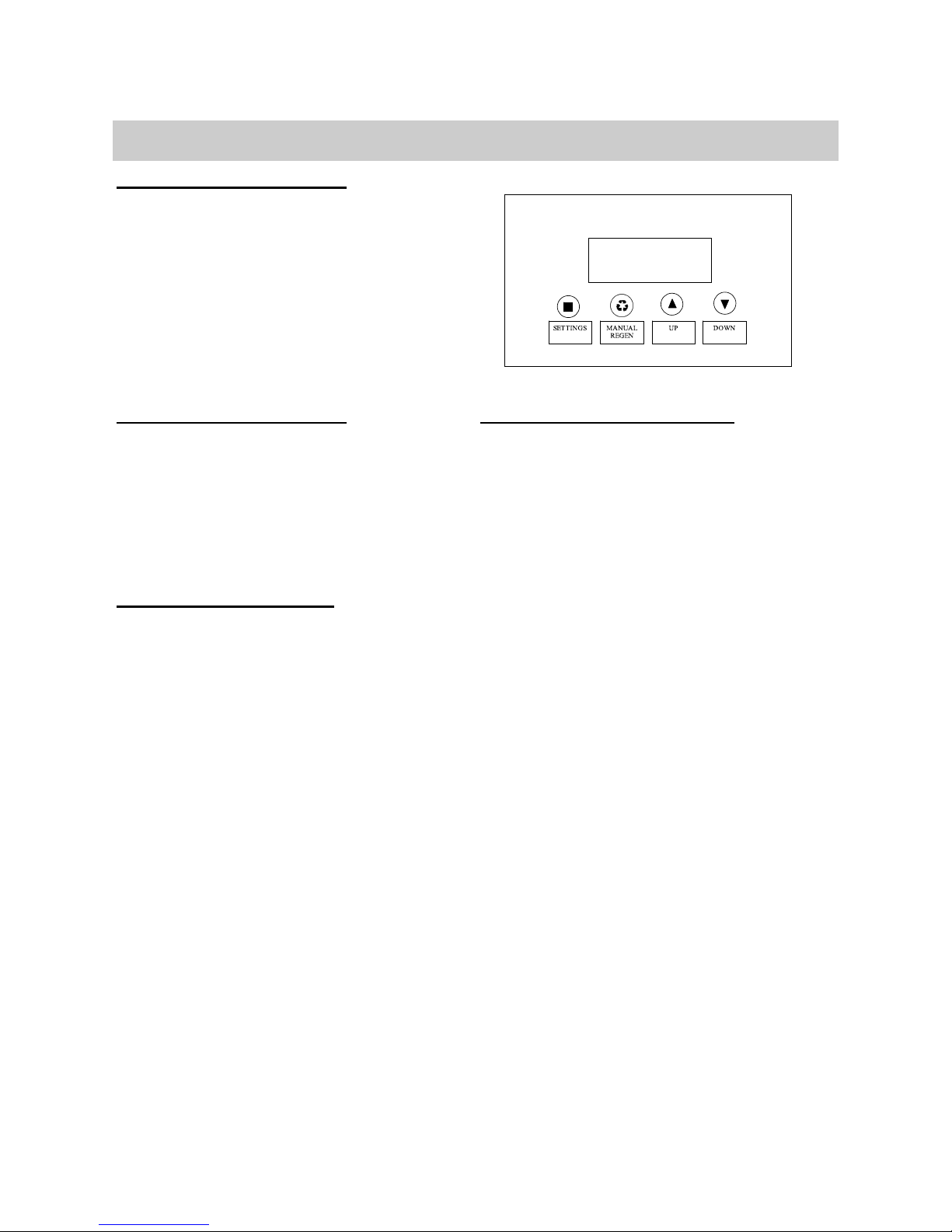
Key Pad Configuration
SETTINGS This function is to enter the basic set up infor
mation required at the time of installation.
MANUAL
EGEN
This function is to initiate an immediate or
delayed manual regeneration.
DOWN /
UP
Increase or decrease the value of the settings
while in the programming mode.
DELAYED REGENERATI N
Press and release the MANUAL REGEN. But-
ton to set a delayed regeneration that will
occur at the regeneration time. The main
dis lay age will show DELAYED REGEN ON.
To cancel ress and release the MANUAL RE-
GEN. Button. The main dis lay age will
show DELAYED REGEN OFF.
IMMEDIATE REGENERATI N
To start an immediate regeneration (or ste
valve through each osition), ress and hold
the MANUAL REGEN. Button for 3 seconds
(until bee s). The valve will start an immedi-
ate regeneration. Press any key to ski to
the next cycle.
Manual Regeneration (Step / Cycle
1. Plug the ower transformer into an a -
roved ower source. Connect the ower
cord to the valve.
2. When ower is su lied to the control, the
screen will dis lay “INITIALIZING WAIT
PLEASE” while it finds the service osition.
3. Manually ste the valve ast the BRINE
osition to the BACKWASH osition. If
screen is locked, ress SETTINGS for 3
seconds to unlock. Press and hold the
MANUL REGEN. Key for 3 seconds. Press
any key to ski the BRINE cycle.
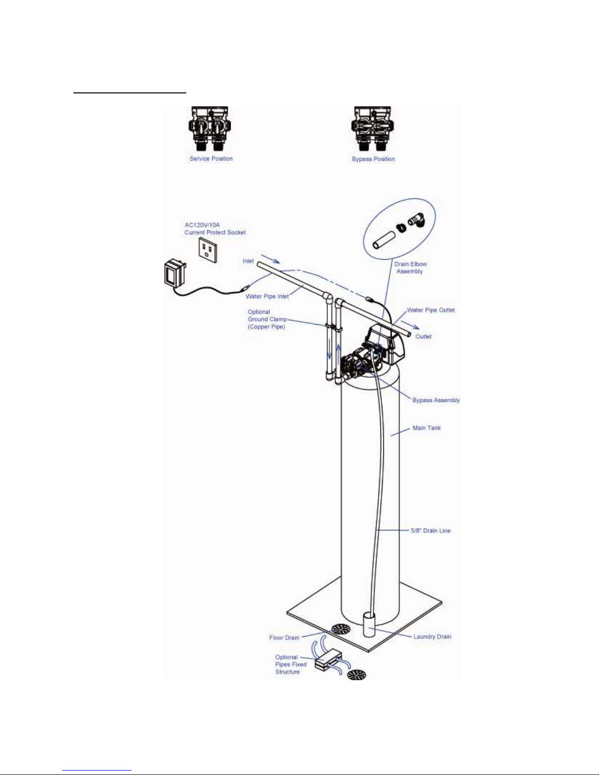
4. pen the inlet on the bypass valve
slightly and very slowly allow water
to enter the unit. (If the water en-
ters too quickly it will push the media
up into the control valve and get
plugged).
5. For carbon filters, once the unit has
filled sufficiently that water is at
least equal to the height of the top of
the media shut down the water for
15 – 20 minutes for the carbon to
soak. Unplug the power cable. After
the carbon has soaked for the recom-
mended time continue by plugging
the power cable back in. For non-
carbon filters allow unit to backwash
3-4 minutes or until drain line is clear
of any fines.
6. Press any button to advance to the RINSE
osition. Check the drain line flow. Allow
the water to run for 3-4 minutes or until
the water is clear.
7. Press any button to advance to the REFILL
osition. Check that the valve is filling wa-
ter into the brine tank. Allow the valve to
refill for the full amount of time as dis-
layed on the screen to insure a ro er
brine solution for the next regeneration.
8. The valve will automatically advance to the
SERVICE osition. O en the outlet valve
on the by ass, then o en the nearest
treated water faucet and allow the water
to run until clear, close the ta and re lace
the faucet screen.
9. Add salt into the cabinet / brine tank.
10. Program unit.

11
The table below can be used to help deter-
mine the frequency of regeneration for Multi-
Media and Taste & Odour filters. Use this ta-
ble as a guide since individual circumstances
will require more or less frequent regenera-
tions. This can be adjusted by the home
owner to suite their individual needs with fre-
quencies available from – 99 days.
To prevent bacterial build up in the media,
activated carbon filters should not exceed 6
days between backwashes.
To set a Neutralizing filter, follow the table
under mild conditions
Sediment Mild Average Extreme
Taste Odor Mild Average Extreme
No. Of Per-
sons Days Between Bac Wash (Regenerations)
26 6 6 6 6 6 6 6 6 6 4 4 4 4 4 4
36 6 6 6 4 4 4 4 4 4 3 3 3 3 3 3
46 6 6 6 4 4 4 3 3 3 2 2 2 2 2 2
56 6 4 4 3 3 3 3 2 2 2 2 1 1 1 1
66 6 4 4 3 3 3 2 2 2 2 1 1 1 1 1
76 4 4 3 3 2 2 2 1 1 1 1 1 1 1 1
86 4 4 3 2 2 2 2 1 1 1 1 1 1 1 1
94 4 3 3 2 2 1 1 1 1 1 1 1 1 1 1
10 4 3 3 2 2 1 1 1 1 1 1 1 1 1 1 1
Backwash Frequency
Programming Instructions
TIME F DAY, YEAR, M NTH, DAY,
Time of day is for normal operation of system and the scheduling of the
regeneration time. The date is used in a diagnostic function to track the
last time the system regenerated.
REGEN DAYS
This value is the number of days between regenerations or back washes to
clean the filters.
GALL NS
Default value is OFF. Adjust the GALLONS to set the capacity. This will
cause the unit to regenerate either when the gallons remaining goes to
zero or the days between regeneration is zero. Which ever occurs first.
REGEN TIME
This setting determines the time of day to perform a scheduled regenera-
tion. The normal regen time for a filter is 2:00 AM.

12
Control peration During A Power Failure
In the event of a power failure, the valve will keep track of the time and day for 48 hours.
The programmed settings are stored in a non-volatile memory and will not be lost during a
power failure. If power fails while the unit is in regeneration, the valve will finish regenera-
tion from the point it is at once power is restored. If the valve misses a scheduled regen-
eration due to a power failure, it will queue a regeneration at the next regeneration time
once power is restored.
Main Display
About The System
Periodically the filter will require a back wash to clean the trapped particles and unpack the
filter bed to restore the system flow rates. The table below explains the regeneration steps.
Regeneration Process
The main display page will pause on the Date and Time page for 5 seconds. Then it will
continually scroll through all of the system diagnostic display pages. Depending on the
Valve Type some pages will not be displayed. To manually scroll through the diagnostics,
press the down or up key. To reset the TOTAL REGENS, TOTAL GALLONS OVER RUN TO-
TAL, or PEAK flow rates, press and hold the MENU until the value changes to zero.
PARAMETER
DESCRIPTION
JULY/17/2012
8:30 PM
TOTAL 1,500 GAL
REMAIN 1,200 GAL
LAST REGEN
9/24/12
TOTAL REGENS
10
TOTAL GALLONS
001590 GAL
TOTAL 4 DAYS
REMAIN 3 DAYS
OVER RUN TOTAL
0000 GAL
CURRENT 1 5 GPM
PEAK 6 5 GPM
DELAYED REGEN
OFF
REGEN TIME
12:00 AM
VALVE MODE
B W FILTER
The current setting for regeneration time
The current setting of the valve mode
The total number of regenerations
The total amount of gallons treated by the system
The total amount of water that has exceeded the system capacity over the last 4
regenerations When remaining goes to zero, the gallons used will be added to over run total
The current flow rate and the peak flow rate since the last regeneration
Advises whether a delayed regeneration has been scheduled manually or automatically
Month, Day, Year, Time
The number of days remaining before regeneration This option is only in filter mode
The total amount is the system capacity when fully regenerated The remaining is the
capacity left in the system
The date of the last regeneration

13
Automatic Raw Water Bypass During Regeneration
The regeneration cycle can last 30 minutes after which filtered water service will be re-
stored. During regeneration, un-filtered water is automatically bypassed for use in the
household. Hot water should be used as little as possible during this time to prevent un-
filtered water from filling the water heater. This is why automatic regeneration is set for
sometime during the night and manual regenerations should be performed when little or no
water will be used in the household.
Normal regeneration time is 2:00 AM.
New Sounds
You may notice new sounds as your filter operates. The regeneration cycle lasts up to 30
minutes. During this time, you may hear water running intermittently to the drain.
Manual Bypass
In the case of emergency you can isolate your water filter from the water supply using the
bypass valve located at the back of the control. In normal operation the bypass is open with
the on/off knobs in line with the inlet and outlet pipes.
To isolate the filter, simply rotate the knobs counter clockwise (as indicated by the word BY-
PASS and arrow) until they lock. You can use your water related fixtures and appliances as
the water supply is bypassing the filter. However, the water you use will be hard. To resume
water service, open bypass valve by rotating the knobs counterclockwise.
System Configuration
Tank Size (Diameter) Drain Line Flow
Control (DLFC)
8" #5 (3.5 GPM)
9" # (5.0 GPM)
10" # (5.0 GPM)
12" #B (7.0 GPM)
14" #C (10.0 GPM)
16" none
Suggested Filter Valve Configuration

14
Maintenance
Care of Your System
To retain the attractive appearance of your new water filter, clean occasionally with mild
soap solution. Do not use abrasive cleaners, ammonia or solvents. Never subject your sof-
tener to freezing or to temperatures above 1 °F.
Maintenance of your new water filter requires very little time or effort but it is essential.
Regular maintenance will ensure many years of efficient and trouble-free operation.
1. Periodically make sure your pump is performing satisfactorily to ensure sufficient water is
available for backwashing the filter.
2. Periodically test your raw and filtered water to ensure conditions are still the same for
your original settings and that the unit is working they way it is intended to. Water test-
ing is often the best way to determine when the filter media will require replacement.
3. Periodically check that the drain line is clear and free from any obstructions.
NE - Neutralizing Filter
- the media bed in a neutralizing filter is slowly dissolved and has
to be replaced. The frequency of replacement varies, depending on water quality - consult
your dealer to determine the expected life of your media bed.
AC - Taste and Odor Filter
- under normal operating conditions the effective life of the
filter media is approximately one to three years, depending on the water quality, after
which, taste and odor problems may return. When this happens, contact your dealer for a
replacement media bed.
MM - Sediment and Turbidity Filter
- under normal operating conditions, the media
should never need to be replaced. However, if you experience pressure loss and cannot cor-
rect it with a manual regeneration, your media bed may need replacing - contact your
dealer.
Repla ing the Media Bed
Check to ensure all media parts are received.
The first step in replacing the media bed is to shut off the water supply to the filter. Then
place the unit into the backwash position to release any pressure in the lines. At this point,
you must disconnect the plumbing from the inlet and outlet. Then unscrew the control
valve from the fibreglass tank. Once this has been done, remove the distributor tube. Then
you can remove the filter media and two types of gravel from the tank. The quickest way to
do this is by simply tipping the tank upside down into a large drum or pail. The tank must
be rinsed out completely and have no media or gravel left in it at all.
Installation & Repla ement Filter Media Pak

15
Loading the Media Pak
Place the distributor tube back down the center of the tank. NOTE: the top of this tube
should be plugged with a rag or cork to prevent media from entering. Pour the bag of
coarse gravel into the tank, and then pour the bag of fine gravel into the tank.
It is important that the distributor tube is not moved or pulled out as it is not possible to put
it down to the bottom of the tank once gravel or media are in the tank.
inally pour the larger bag(s) of media into the tank in the following order:
Multimedia Filters
1. Coarse gravel (1/2 x 1/4) 4. ine garnet (30 x 40)
2. ine gravel (1/8 x 1/16) 5. ine filter sand (.45 x .55)
3. Coarse gravel (8 x 12) 6. Anthrafilt
ACF Carbon Filters Neutralizing Filters
1. Coarse gravel 1. Coarse gravel 4. Mag Oxide
2. ine gravel 2. ine gravel
3. Carbon 3. Calcite
Once this is done, the rag or cork should be removed from the distributor tube. Clean off
the top of the tank. inally place the control valve on the tank and on to the distributor
tube. Tighten the control valve on to the tank. Connect or reconnect the inlet and outlet and
drain. The control valve should be in the backwash position. Slowly open the inlet valve wa-
ter supply and slowly fill the filter tank until water appears at the open drain line. Return the
control to the service position and shut the inlet off for approximately one hour to allow the
media to soak in the water.
After one hour, turn inlet water on slowly and place the control into the backwash position
and plug the unit’s electrical cord into a constant power source. Let the unit continue
through its regeneration cycle automatically. The regeneration is necessary so all media
fines are backwashed down the drain to ensure clean filtered water.

16
Main Repair Parts
Replacing Drain Line Flow Control (DLFC)
1. Remove the red clip that secures the drain line elbow.
2. Remove the BL C washer from the elbow fitting.
3. Reassemble using the reverse procedure.

17
Filter Exploded View
Brine tank for softener
system only.

18
A A A
B
D
F
E
A
C
Main Repair Parts - Connectors

19
VALVE REPAIR PARTS LIST
Replacement
Part Number Part Description Replacement
Part Number Part Description
60010127 INJECTOR SET #0000 BLACK 60010129 85HE UPFLOW PISTON ASSEMBLY
60010126 INJECTTOR SET #000 GREY 60010171 85HE OWNFLOW PISTON ASSEMBLY
60010035 INJECTOR SET #00 VIOLET 60010130 85HE SEAL & SPACER KIT
60010034 INJECTOR SET #0 RE 60010131 85HE LFC #1 1.5 GPM
60010033 INJECTOR SET #1 WHITE 60010132 85HE LFC #2 2.0 GPM
60010032 INJECTOR SET #2 BLUE 60010133 85HE LFC #3 2.4 GPM
60010031 INJECTOR SET #3 YELLOW 60010135 85HE LFC #5 3.5 GPM
60010128 BLFC 0.2 GPM 60010136 85HE LFC #A 5.0 GPM
60010110 BLFC 0.3 GPM 60010137 85HE LFC #B 7.0 GPM
60010082 BLFC 0.7 GPM 60010138 85HE LFC #C 10.0 GPM
Control Valve Exploded View

20
Control Valve Parts List
Replacement
Part Number
MF G Part Number Part Description DWG # Quantity
5056087 Screw-M5x12(Hexagon) A01 3
5056088 Screw-M5x16(Hexagon With Washer) A02 2
5056047 nd Plug Retainer A03 1
5031016 BNT85H Piston Rod A04 1
5056097 Piston Pin A05 1
5031015 BNT85H Quad Ring Plug Cover A06 1
5056070 Quad Ring A07 2
5031011 BNT85H nd Plug A08 1
5031014 BNT85H Piston Retainer A09 1
5057001 BNT85H Piston( lectrical Downflow) A10 1
5056073 Seal A11 5
5056021 Spacer A12 4
5010082 Drain Fitting-B A13 1
5031005 BNT85H Spacer A14 1
5056186 DLFC-2# A15 1
5056172 Secure Clip-s A16 2
5031002 BNT85H Valve Body A17 1
5056508 Screw-M5x12(Hexagon With Washer) A18 5
5030004 BNT85 nd Cover A19 1
5030013
O-Ring-
¢
30×2.65 A20 1
5056063 O-Ring-¢78.74×5.33 A21 1
26010103 O-Ring-¢25×3.55 A22 1
7060007 Valve Bottom Connector A23 1
13000426 Screw-ST2.9X13(Large Washer) A24 2
5031022 O-Ring-¢32×3 A25 1
5031021 O-Ring-¢18×3 A26 1
5031013 Injector Plug Body A27 1
30110007 Plastic Ball ¢6 A28 1
30040089 Injec tor Throat A29 2
5031012 BNT85H Injector Fixed Sleeve A30 1
30040090 Injec tor Nozzle A31 2
5056103 Injector Screen A32 1
5031003 BNT85H Injector Cover Body A33 1
5031018 O-Ring-¢40×2.65 A34 1
5031004 BNT85H Injector Cover Cap A35 1
5031027 Screw-M5x25(Hexagon With Washer) A36 4
5056075 Seal Mat A37 1
5056134 O-Ring-¢12×2 A38 3
5056054 Injector Stem A39 1
5056031 Injector Spacer A40 1
5056081 O-Ring-¢12.5×1.8 A41 1
5056030 Injector Cap A42 1
5056093 Injector Screen A43 1
5010049 Special Washer A44 1
5056105 Retaining Ring A45 1
5031010 BNT85H BLFC Fixed Sleeve A46 2
5056076 BLFC-2# A47 1
5005629 Injector Fitting(3/8". lbow) A48 1
785 CON ROL VALVE (DOWNFLOW)
Table of contents
Other Canature Water Dispenser manuals
Popular Water Dispenser manuals by other brands

DVA
DVA LT Series manual

Glacial
Glacial 7LIECH-BP-G user manual

KitchenAid
KitchenAid 3184330 Installation Instructions and Use & Care Guide

Cosmetal
Cosmetal NIAGARA Installation, use and maintenance handbook

Newco
Newco Nexus CT SIP quick start guide

MARLO
MARLO NXT2 Series Installation, operation and maintenance manual

Omnifilter
Omnifilter U25 Series E installation instructions

Hydronix
Hydronix Hydro Guard HDGT-45 Installation instructions manual

Bosch
Bosch BRITA INTENZA instruction manual

BWT
BWT Rondomat HVD Series Installation and operation manual

Cornelius
Cornelius CR50Aqua operating instructions

Hidrotermal
Hidrotermal ARS-12.5 Installation and maintenance manual