JohnsonFit HT5.0 User manual

HT5.0 SERVICE MANUAL
1

TABLE OF CONTENTS
CHAPTER 1: Serial Number Location…………………………………………3
CHAPTER 2: Console Operation…………………………………………………4
CHAPTER 3: Troubleshooting & Maintenance…………………………………7
3.1 Common Product Questions……………………………………………7
3.2 Basic Troubleshooting……………………………………………………7
3.3 Maintenance………………………………………………………………9
CHAPTER 4: Part Replacement…………………………………………………10
4.1 Console Replacement……………………………………………………10
4.2 Crank Weldment Replacement…………………………………………10
4.3 Drive Belt Replacement …………………………………………………11
4.4 Main Axle Bearing Replacement ………………………………………12
4.5 Transmission Axle BearingReplacement ……………………………13
2

CHAPTER 1: Serial Number Location
The serial number is located on the front base of the frame.
3

CHAPTER 2: Console Operation
4

DISPLAY WINDOWS
5

6

7

Chapter 3: Troubleshooting & Maintenance
3.1 COMMON PRODUCT QUESTIONS
Are the sounds my equipment makes normal?
Our equipment is some of the quietest available because they use belt drives and
friction
free magnetic resistance. We use the highest grade bearings and belts to
minimize noise.
However, because the resistance system itself is so quiet, you will
occasionally hear
other slight mechanical noises. Unlike older, louder technologies, there
are no fans,
friction belts, or alternator noises to mask these sounds on our equipment.
These
mechanical noises, which may or may not be intermittent, are normal and are
caused by
the transfer of the significant amounts of energy to a rapidly spinning flywheel.
All
bearings, belts or other rotating parts will generate some noise which will transmit
through the casing and frame. It is also normal for these sounds to change slightly during
a workout and over time because of thermal expansion of the parts.
Why is the equipment I had delivered louder than the one at the store?
All fitness products seem quieter in a large store showroom because there is general
more background noise than in your home. Also, there will be less reverberation on a
carpeted concrete floor than on a wood overlay floor. Sometimes a heavy rubber mat will
help reduce reverberation through the floor. If a fitness product is placed close to a wall,
there will be more reflected noise.
How long will the drive belt last?
The computer modeling we have done indicated virtually thousands of maintenance free
hours. Belts are now commonly used in far more demanding applications such as
motorcycle drives.
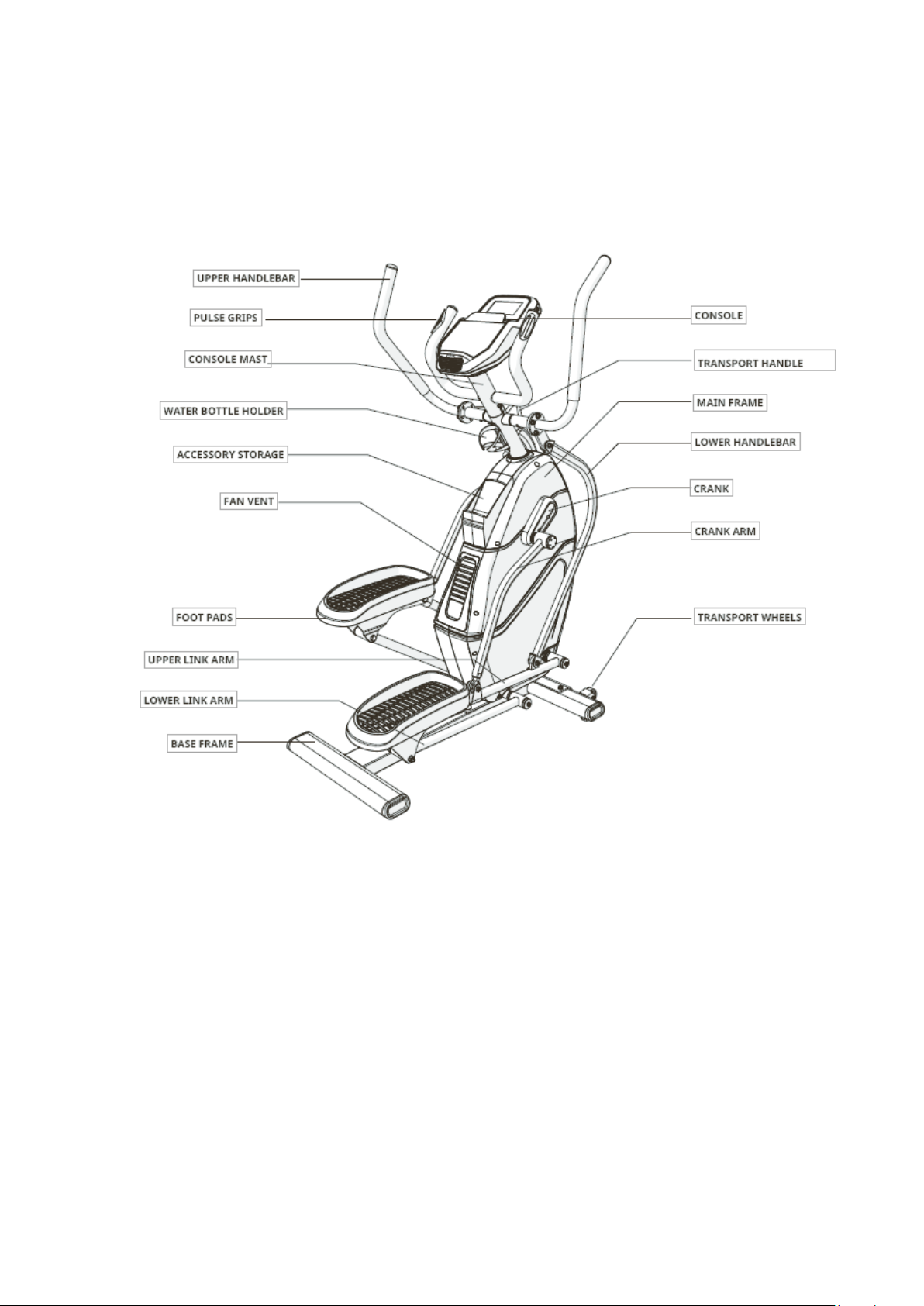
Can I move the trainer easily once it is assembled?
Your equipment has a pair of transport wheels built into the front stabilizer tube. Please
follow the MOVING THE EQUIPMENT section in the Owner’s Manual to transport
your
equipment. It is important that you place your equipment in a comfortable and
inviting
room. Your equipment is designed to use minimal floor space. Many people
will place
their equipment facing the TV or a picture window. If at all possible, avoid
putting your
equipment in an unfinished basement. To make exercise a desirable daily
activity for you,
the equipment should be in a comfortable setting.
3.2 BASIC TROUBLESHOOTING
3.2.1Problem: The console does not light up.
Solution: Verify the following:
Make sure the outlet which the machine is plugged into is functional. Double check
that the breaker has not tripped.
8

The correct power cord is being used. Only use the power cord included or
provided by your local dealer.
The power cord is not pinched or damaged and is properly plugged into the outlet
and the machine.
Unplug the power cord, remove the console and check that all connections to the
console are secure and not damaged or pinched.
3.2.2Problem: The console lights up but the Distance/Watts/RPM do not count.
Solution: Verify the following:
Turn off the machine and unplug power cord. Remove the console and check that
all connections to the console are secure and not damaged or pinched.
If doing the above does not fix the problem, the speed sensor and/or magnet may
have become dislodged or damaged.
3.2.3Problem: The resistance levels seem to be incorrect, seeming too hard or too easy.
Solution: Verify the following:
The correct power cord is being used. Only use the power cord provided or
authorized by your local dealer.
Reset the console and allow the resistance to reset to the default position. Restart
and retry the resistance levels.
3.2.4Problem: The equipment makes a squeaking or chirping noise.
Solution: Verify the following:
The equipment is on a level surface.
Loosen all bolts attached during the assembly process, grease the threads, and
tighten again.
Apply lithium-based grease to the top surface of the guiderails.
3.2.5Problem: When
an audio device
is connected, there is no sound coming from the
speakers or
the speakers sound fuzzy.
Solution: Make sure audio cable is plugged in securely to both the console and MP3
player jacks.
3.2.6Problem: Heart rate abnormal (Grip-pulse only)
Check your exercise environment for sources of interference such as fluorescent lights,
computers, underground fencing, home security systems or appliances containing large
motors. These items may cause erratic heart rate readouts.
You may experience an erratic readout under the following conditions:
Griping the heart rate handlebars too tight. Try to maintain moderate pressure while
holding onto the heart rate handlebars.
Constant movement and vibration due to constantly holding the heart rate
handlebars while exercising. If you are receiving erratic heart rate readouts, try to
only hold the grips long enough to monitor your heart rate.
8

When you are breathing heavily during a workout.
When your hands are constricted by wearing a ring.
When your hands are dry or cold. Try to moisten your palms by rubbing them
together to warm.
Anyone with heavy arrhythmia.
Anyone with arteriosclerosis or peripheral circulation disorder.
Anyone whose skin on the measuring palm is especially thick.
3.3 MAINTENANCE
What kind of routine maintenance is required?
Minimal maintenance and cleaning is required. Adhering tothis schedule will extend
the life of your machine.
How do I clean my bike?
Clean with soap and water cleaners only. Never use solvents on the plastic parts.
Cleanliness of your equipment and its operating environment will keep maintenance
problems and service calls to a minimum. For this reason, it is recommend that the
following preventive maintenance schedule be followed.
1) Clean the equipment: (Daily)
•
Turn off the equipment by unplugging the power cord from the wall outlet.
•
Wipe down the equipment with a damp cloth. Never use solvents, as they can
cause damage to the equipment.
•
Inspect the power cord. Ifthe power cord is damaged, reference contact
information on the back cover ofthe INFORMATION CARD for a
replacement.
•
Make sure the power cord is notunderneath the equipment or in any other
area where it can become pinched or cut during storage or use.
2) Clean underneath the equipment: (Weekly)
•
Turn off the equipment by unplugging the power cord from the wall outlet.
•
Move the equipment to a remote location.
•
Wipe or vacuum any dustparticles or other objects that may have
accumulated underneath the equipment.
•
Return the equipment to its previous position.
3) MONTHLY
•
Inspect and tighten all assembly bolts and pedals on the machine
•
Clean any debris off ofthe pedal arms and link arms.
4) BI-MONTHLY
•
Lubricate the link arm joint with Silicone lubricant (included). Apply 1-2 drops
on left and right side of link armjoints.
9

Chapter 4: Part Replacement
4.1 CONSOLE REPLACEMENT
Tools required: Screwdriver
Steps:
a.
Unscrew the screws on the console mast with a screwdriver. (Figure 1)
b.
Pull out the console wire and unplug the connectors. (Figure 2)
c.
Replace with a new console and reverse the above steps to reassemble.
Figure1 Figure 2
4.2 CRANK WELDMENT REPLACEMENT
Tools required: 13#/17# open
spanner;5mm/8mm allen wrench; screwdriver ;hammer
Steps:
Figure3
Figure4
Figure5
Figure6
Figure7
Figure8
Figure9
Figure10
Figure11
Figure12
10

a.
Remove the bolt and nut securing the crank arm to the upper link arm with the
13# open spanner( Figure 5)
b.
Remove the axle cover (Figure 6)
c.
Remove the bolt securing the crank arm to the crank with the 13# open
spanner( Figure 7)
d.
Slide the ends of the crank arm off the axle( Figure8)
e.
Remove the screws (2pcs) fixed on the crank cover with a screwdriver,Remove the
crank cover( Figure9)
f.
Remove the bolts and nuts securing the crank weldment to the main axle with the
17# open spanner and 5mm/8mm allen wrench ( Figure 10 & Figure 11)
g.
Slide the ends of the crank weldment off the main axle( Figure12)
h.
Replace with a new crank weldment and reverse the above steps to reassemble.
4.3 DRIVE BELT REPLACEMENT
a.
Remove the crank weldment as mentioned in 4.2 from step a to step h.
b.
Remove the accessory storage (Figure 13)
c.
Remove the screws fixed on the chain cover and the screws on the bottom of the
chain cover with a cross screwdriver. ( Figure 14&15)
d.
Remove the fan vent (Figure 16)
e.
Remove the chain cove(Figure 17)
f.
Pull the drive belt free of the crank pulley,small flywheel and idle pulleys(Figure 18)
g.
Replace with a new drive belt and reverse the above steps to reassemble.
Figure13
Figure14
Figure15
Figure16
Figure17
Figure18
Figure17
Figure18
11

4.4 MAIN AXLE BEARING REPLACEMENT
Tools required: 32# open
spanner; hammer
Steps:
a.
Remove the crank weldment as mentioned in 4.2 from step a to step h.
b.
Remove the chain cover as mentioned in 4.3from step a to step e.
c.
Remove the retaining nuts fixed on the crank axle with the 32# open spanner( Figure
19& 20)
d.
Remove the drive belt as mentioned in 4.3 step f.
e.
Use a hammer to gently tap the crank axle out of the frame (Figure 21)
f.
Use a hammer to gently tap the bearing out of the frame. (Figure 22)
g.
Wipe the bearing hole clean and replace with a new bearing. (Figure 23)
h.
Reverse the above instructions to reassemble.
Figure19
Figure20
Figure21
Figure22
Figure23
12

4.5 TRANSMISSION AXLE BEARING REPLACEMENT
Tools required: Shaft pullout device; 10mm socket key
Steps:
Figure23
Figure24
Figure25
Figure26
Figure27
Figure28
Figure29
Figure30
Figure31
Figure32
Figure33
Figure34
13

a.
Remove the chain cover as mentioned in 4.3from step a to step e.
b.
Remove thetransmission belt.(Figure25)
c.
Use a bar tosecure the flywheel to prevent rotation;remove theflywheel with the
shaft pullout device and extended wrench(Figure23&26)
d.
Using a 10mm socket key,remove the screws fixed on the fan wheel and remove
th
e
fan wheel (Figure24&27)
e.
Use a hammerto gently tap thetransmission axle out of the frame.(Figure28)
f.
Use a hammerto gently tap thebearing out of the frame.(Figure29)
g.
Wipethe bearinghole clean and replace witha new bearing.(Figure30)
h.
Install the transmission axle onto the frame(Figure31)
i.
Place the frame sideways with a support block(height:280mm) underneath and
spread a layer of machine grease over the axle, then install the flywheel (Figure
32&33)
j.
Turn the flywheel by hand to confirm that the bearing will turn smoothly. (Figure34)
k.
Reverse theabove instructions to reassemble.
14
Table of contents