Jonco BC26 User manual

BC26 Self propell Brush Cutter
Owner’s Manual
IMPORTANT- READ CAREFULLY BEFORE USE AND KEEP FOR FUTURE REFERENCE


1
SPECIFICATIONS
BC26
Gasoline engine
Engine Type
Displacement
Fuel Capacity 1.5L
Oil Capacity 0.6L
Unit Weight 82kg
Overall Length 1.6m
Overall Width 0.7m
Overall Height 1.0m
Maximum Operating
Slope 20o
196cc

UNPACKING
Your Self-Propelled Brush Cutter was shipped in one carton, completely assembled except for the upper handle assembly
and the front guard bar. Mounting hardware for the handle and guard bar is temporarily installed on the handle bracket and the
front of the deck assembly.
READ all safety instructions before assembling unit.
2
INSTRUCTION LABELS
The labels shown below were installed on your Brush Cutter. If any labels are damaged or missing, replace them before
operating this equipment.
DISCONNECT spark plug wire before assembling unit.

3
ASSEMBLY
1. REMOVE unit from carton and check the contents of the parts bag.
2. REMOVE mounting hardware from the hardware bag.
3. ATTACH the handle to the engine base BY tighten C.
4. TIGHTEN mounting hardware on handle braces.
5. ATTACH guard bar to Skid bar by installing the side bolts
6. Rotary latch D, Release the latch, then turn the handle, Replace the latch to lock
the handle.
OPERATION
OPERATOR CONTROLS
The operator’s station is at the rear of the machine between the handlebars. The operator should STAND in a position to allow
both handlebars to be grasped firmly and which allows sufficient leverage to steer the machine. Operator’s controls are shown
below.
Operator Control Locations
A Propelling Clutch Lever
B Blade Clutch Lever 1 STOP engine
2 Choke and start engine
3 Work
Fig. 1

4
CUTTING OPERATION
1. Press blade clutch lever Bdown to engage blade. Allow blade to spin up to normal operating speed.
2. Press propelling clutch level Adown to engage transaxle in FORWARD direction.
CLEARING A CLOGGED DECK
DISCONNECT spark plug wire before servicing unit.
1. Shut engine off and wait for blade to stop completely.2
.Disconnect spark plug wire.
3. Remove clog from cutting deck.
WEAR durable gloves. Clog may contain sharp materials.
4. Reconnect spark plug wire.
SHUT DOWN
1. Release PROPELLING levers(A) to disengage transaxle.2
.Release blade clutch lever (B) to disengage blade.
3. (Non-Electric) Move the throttle to the "STOP" position on the throttle control.
STARTING ENGINE
CHECK engine oil level before operating machine.
DO NOT START equipment with drive or blade clutch engaged.
1. Place equipment on a level, firm surface that is free of rocks or other debris.
2. Place throttle in “Choke and start”position. (See Fig. 1)
3. Pull choke out.
4.Units equipped with manual starters: Pull starter rope to start engine.
5.Push throttle to " WORK" position.
6.Pull throttle control back to and allow engine to reach correct operating speed.
NOTE: PULL STARTER CORD slowly until resistance is felt. Then pull cord rapidly to avoid kickback

5
COMMON REPLACEMENT PARTS
Blade.
Transaxle Drive Belt.
Blade Drive Belt.
Side deck skid.
Throttle Control Assembly. Throttle control including cable.
CLEANING
Your Brush Cutter should be cleaned periodically to ensure optimum performance and service life. Clogs and debris should
be removed from the blade area and debris should be removed from the engine cooling fins. A garden hose or pressure
washer may be used for cleaning.
DO NOT SPRAY WATER DIRECTLY ON THE BLADE CLUTCH WHEN USING A POWER
WASHER.
BLADE SHARPENING AND REMOVAL
READ all safety instructions before servicing unit.
1. Disconnect spark plug wire.
2. Lift and support front of unit to allow access to underside.
DISCONNECT spark plug wire before servicing unit.
MAINTENANCE
PERIODIC MAINTENANCE
Periodic maintenance should be performed at the following intervals:
Maintenance Operation Every
Use Daily or Every
5 Hours Every 25
Hours Every 50
Hours Every 100-150
Hours
Inspect for worn or damaged parts
Check for excessive vibration
Inspect for loose parts
Sharpen blade. Note: nut will need to be
replaced when blade is removed
Inspect belts for wear
Lubricate throttle control cable and linkage
Check blade clutch cable tension
Apply anti-seize compound to rear axles
Replace blade drive and transaxle drive belts

6
BLADE DRIVE AND TENSION
NOTE: The Blade Drive belt is under constant tension by the idler arm on the deck
DISCONNECT spark plug wire before servicing unit.
1.Disconnect spark plug wire.
2. Loosen six screws holding belt deck top plate (item26) and remove the plate.
3. Examine condition of belt and amount of tension on belt.
4. If the idler (item14) is not providing enough tension inspect the spring attaching it to the spindle base. If not enough
tension is being put on the arm, replace the spring.
5. Replace engine plate and secure with screws removed earlier.
6. Reconnect spark plug wire.
7. Check belt tension by operating unit under conditions that caused belt slippage. If belt continues to slip it may require
replacement before operation can be continued.
BLADE CLUTCH ADJUSTMENT
DISCONNECT spark plug wire before servicing unit.
If clutch continues to slip or squeal, do not operate equipment until adequate adjustment or repair has been
performed. Improper adjustment can cause clutch to overheat and slip, greatly reducing performance and clutch life.
1. Disconnect spark plug wire.
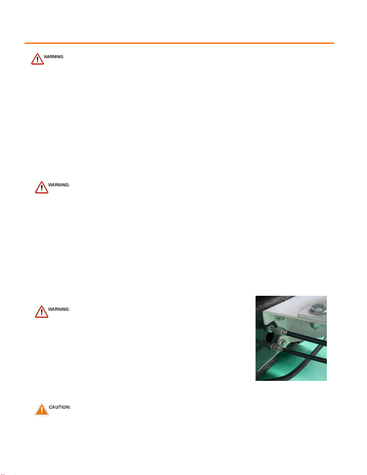
2. As the clutch/brake wears or begins slipping or squealing, adjustment may be
required to maintain proper cable tension and clutch engagement. A properly
adjusted blade clutch should require 10 lbs. of force to depress the end of the
clutch lever. The blade clutch cable spring should stretch 1/4” to 3/8” (6.4-9.5
mm).
3. Adjust cable tension by tightening or loosening cable adjustment nut on rear of
engine base (See Fig. 9). Be sure to leave enough slack in cable to allow
blade brake to engage.
4. Reconnect spark plug wire.
Fig. 9
UNIT IS HEAVY. Make sure support is adequate to support weight of machine.
3. Block blade to prevent it from rotating during removal.
4. Remove blade bolt , and friction washer .
5. Remove blade and install replacement blade. When replacing the blade use ORIGINAL PARTS
NOTE: When sharpening blade make sure to sharpen all cutting edges. If the lock nut is removed and replaced more
than once, it should be replaced with a new lock nut.
6. Attach new blade with new blade bolt, and new friction washer removed earlier included with your new blade.
NOTE: Inspect fasteners for wear and replace if necessary.
7. Torque blade lock nut to 40 ft-lbs.
8. Reconnect spark plug wire.

5. Slip the belt off of the transaxle pulley.
6. Replace the belt in reverse order.
NOTE: See Fig 12 for proper belt routing.
TRANSAXLE DRIVE BELT REMOVAL AND REPLACEMENT
BLADE DRIVE BELT REMOVAL AND REPLACEMENT
DISCONNECT spark plug wire before servicing unit.
1. Disconnect spark plug wire.
2. Lift and support the rear of the unit to allow access to the underside
3. Unattach the spring from the bracket that is keeping tension on the drive belt.
4. Walk the belt off of the clutch by slowly pulling the engine over.
1. Disconnect spark plug wire.
2. Lift and support rear of unit to allow access to underside.
UNIT IS HEAVY. Make sure support is adequate to support weight of machine.
3. Loosen six screws holding belt deck top plate (item26) and remove the plate.
4. Follow the steps 3 and 4 in the Transaxle drive belt removal section to removethe Transaxle drive belt.
5. Relieve the tension on the blade belt by pulling the deck idler arm off of the belt. Then walk the belt off of the deck pulley.
6. Feed the belt back to the engine base then slip the belt off of the clutch.
7. Install the new belt in reverse order making sure the belt is seated properly in the clutch.
WARNING: use caution not to pinch
fingers between the belt and clutch
NOTE: make sure the belt is seated properly in the clutch and transaxle and make sure that it does not bend over the fan blades on
the transaxle.
NOTE: It may be necessary to pry idler pulley away from its original position to release belt, using a ratchet with an
extension in the square hole on the idler arm should allow the proper leverage to pull it off the belt.
8. Reconnect spark plug wire
7

8
TRANSAXLE DRIVE ADJUSTMENT
DISCONNECT spark plug wire before servicing unit.
DECREASE
INCREASE
1. Disconnect spark plug wire.
2. Adjustments to cable tension are made at the barrel entering the Drive
Control Levers.
3. Adjust cable tension by tightening or loosening cable adjustment barrel
on rear of engine base .
4. Reconnect spark plug wire.
Belt Routing Diagram
(Top View of Machine)
Blade Drive Belt (with Transaxle
Belt not Shown)
LOOKING THROUGH TOP
Transaxle Drive Belt
(Seated below drive belt on
clutch)
NOTE:
Moving the cable adjustment barrel OUT increases tension. Moving the barrel IN decreases tension. Increasing the tension too
much will cause the drive to stay engaged whereas not enough will cause it not to engage when the lever is pulled.

9
TROUBLESHOOTING
Problem
Possible Cause
Corrective Action
Engine will not start
Throttle is set to Slow/Stop position.
Move throttle to fast position.
Out of gasoline.
Fill gas tank.
Old or contaminated gasoline.
Drain gas tank and fill with fresh
gasoline.
Spark plug wire disconnected.
Connect spark plug wire.
Dirty air cleaner.
Clean or replace air cleaner.
Blade drive cable tension incorrect. Adjust blade drive cable tension.
Will not cut or cutting performance is
poor Dull blade. Sharpen or replace blade. NOTE: a
new bolt will need to be installed if
blade is removed.
Clogged deck. Unclog deck.
Excessive debris built up on or blocking
blade. Clear debris from blade area.
Engine RPM set too low. Check engine RPM.
Abnormal vibrations Blade loose or out of balance. Check blade for tightness. Rebalance if
necessary.
Engine loose. Check engine mounting bolts.
Blade drive belt worn. Replace blade drive belt.
Belt slips or smokes Belt tension too low. Adjust belt tension.
Belt worn or stretched. Replace belt.
Pulleys worn or damaged. Replace pulleys.
Clutch slips or squeals Clutch cable tension too low. Replace spring on idler arm.
Clutch worn or damaged. Replace worn or defective clutch
assembly parts.
Blade brake will not engage Inadequate slack in clutch cable. Adjust clutch cable.
Clutch worn or damaged. Replace clutch/brake assembly.
Transaxle will not engage Clutch lever not engaging clutch. Adjust clutch cable.
Clutch cable defective. Replace cable.
Belt worn or broken. Replace belt.
Transaxle will not disengage Clutch cable out of adjustment. Adjust clutch cable.
Engine will not turn over Defective blade clutch. Replace clutch.
Engine problem. Contact an authorized servicing dealer
for your engine.

10
BC26 PARTS DRAWING
# item
1 Chassis
2 Blade
3 Blade disk
4 Support disk
5 Gear cover
6 Gear
7 Belt oover
8 Pulley cutter
9 Spindle holder
10 Bear A
11 Spindle
12 Spindle cover
13 Belt
14 Tension pulley
15 Bearing B
16 Cutter clucth handle
17 Propell clucth handle
18 Throttle
19 Handle
20 Handle bracket
21 Handle holder
22 Engine
23 Axle lock bush
24 Wheel
25 Cover
26 Top plate
27 Top cover
28 Comb chain
29 Rod
30 Chain bracket


Table of contents