Jorvet J0453 User manual

JORVET DENTAL
POLISHING UNIT
J0453 |USER MANUAL
PACKAGE CONTENTS
uPolisher Base Unit
uFoot Control Pedal
uPower Cord
uVariable Speed Micromotor
uMicromotor Rest Stand
uStraight Hand Piece
uMetal Prophy Angle/3 Disposable
u10 Rubber Prophy Cups
u10 Cups Prophy Paste
uWarranty Card


CONTENTS
Overview & Warranty
Note Before Using
Installation Guide
Control Panel Functions
Getting Started
First Time Set-Up
Trouble Shooting
To Polish after Cleaning/Scaling
Prophy Head Maintenance
Polishing Tips
Use of Diamond Burrs/Cutting Discs
Regular Maintenance
Technical Specs
Optional Accessories
04
05
06
07
08
09
10
11
Thank you for using our JorVet J0453 Pro Scale Polisher/Variable Speed Micromotor.
We want you to get the most out of the machine and to have your experience in using
it proceed with ease. Detailed instructions are provided on how to correctly use it and
how to take full advantage of all operations and functions. Please read this entire user
manual carefully before operation of your Pro Scale unit.

4
OVERVIEW
WARRANTY
Before using the Polisher Unit, please carefully read this User Manual. The
manual contains installation procedures and operational tips.
Important Notes!
uAC power cord must be grounded with this equipment.
uThis unit should be powered from a separate wall outlet with grounding point.
Attention!
uAvoid use of this machine around Pacemakers.
uIt has been shown that electronic appliances including razors, hair dryers,
microwave ovens, TV receptors, and some electronic medical equipment
may interfere with the normal operations of pacemakers. For further readings
on the subject, please refer to:
“Advances in Cardiac Pacemaker” - The New York Academy of Sciences,
Vol. 167, Article 2, pp. 515-1075
“Electromagnetic Radiation Interference with Cardiac Pacemaker” - U.S.
Department of Health, Education and Welfare
“The Individual with a Pacemaker in the Dental Environment” - Journal of
the American Dental Association, Vol. 91, No.6, pp. 1224-1229
Please be sure to complete and mail the warranty card that is enclosed as
soon as you receive the unit. Each Pro Scale unit is warranted for a period of 18
months against manufacturing or material defects. If you choose to use our free
loaner service, please note that you will be charged for shipping to and from your
location. We DO NOT issue call tags.
For customer service, please call Jorgensen Laboratories.
1.800.525.5614 |970.669.2500

5
NOTE BEFORE USING
INSTALLATION GUIDE
uThe power cord must be grounded. If this requirement is not met, damage could occur
to the polishing unit and/or the user.
uThe unit should be placed on a steady and stabled platform or table. Placing the unit on
an unstable tilted table may degrade the performance and/or may cause damage to the
system.
uDO NOT dismantle the unit on your own or by uncertied technicians. Violation of the
requirement may cause harm to the user and/or damage the unit. This will also void the
warranty.
uFor electrical safety, the power cord should not be placed under heavy objects and high
temperature heat sources should be avoided.
uIf you have any problems while the unit is in use, unplug cord for safety.
Unpacking
u
When unpacking the box, check this unit for any damage. If damaged, please
contact Jorgensen Laboratories immediately.
u
Enter the unit serial number on your warranty card and mail it within 10 days of
receiving your unit.
Environment
u
The unit should be stored in a clean, dry environment. The following environmental
limitations apply to both storage and shipping.
u
Temperature
35° F - 85° F
u
Labels
The meaning of labels printed on the outside of the box are listed below.
Before Starting The Unit
u
Check the JorVet J0453 and make sure both Power and Digital Display are o when
the switch is o.
u
Plug the unit into a grounded outlet.
uConnect the micromotor.
KEEP AWAY FROM WATER THIS SIDE UP

6
CONTROL PANEL FUNCTIONS
FRONT
BACK
1
1
Select Button
Turns unit On/O
LED Display - x100rpm
Indicates motor running and speed
Micromotor Outlet
Connects to micromotor cord
Speed Control
Increases/Decreases speed
1 3
2 4
Forward/Reverse Switch
Micromotor forward or reverse function
AC Input
Connects to electric cord
Foot Pedal Outlet
Connects to foot pedal cord
Fuse Box
Replaceable T2A 250Vac fuse
1 4
On/O Switch
On (-), O (o)
3
2 5
2
2
3
3
4
4
5
GETTING STARTED
CONTROL PANEL FUNCTIONS
On the front panel of the Pro Scale Polisher, you will nd the following switches or dials
which control the unit
u
Power switch with LED indicator. Controls the power source, i.e. remote foot pedal.
u
On/O switch on top of the left side.
uSpeed Control which controls the RPM of the micromotor. Speeds may be set from
300 to 30,000rpm. Lower speeds up to 3,000rpm should be used for polishing.
Higher speeds should be used for cutting or drilling.
NOTE: The red switch on the back of the unit controls the forward/reverse direction
of the micromotor

7
FIRST TIME SET-UP
TROUBLE SHOOTING
Connect
u
The power cord to the unit. Plug the cord into an electrical outlet.
u
The foot pedal switch to the back of the unit into the receptacle. Place the pedal on
the oor.
u
The micromotor to the back of the unit into receptacle on the far left-hand side of the
unit. Lock the connector in place.
The Polisher is Assembled as Follows
u
The straight hand piece is pushed onto the rod above micromotor. It will snap into
place.
u
The prophy angle is next; attach on top of the straight hand piece.
u
The locking ring on the straight hand piece needs to be in the open position. It is
pushed down and to the right.
u
The prophy angle is placed on the straight hand with cut out portion place over
the raised bubble on the straight hand piece.
u
The locking ring is moved left (counter-clockwise) so that the two depressed dots
are in alignment. If the locking ring is not engaged, the prophy angle will not spin.
u
To remove the prophy angle, simply reverse the above procedure.
To help troubleshoot the most common problems, please review the chart below. Should
a problem or malfunction not be resolvable, please turn o unit and immediately contact
Jorgensen Laboratories 800.525.5614.
PROBLEM POSSIBLE CAUSE SOLUTION
No Power Unit not properly connected Check all plugs for proper connection
Foot Switch
Sticks Open
Foot pedal internal spring is stuck Hold foot pedal in hand, toggle
back and forth to loosen the spring
Twisted foot pedal cord Make sure the cord is untwisted
where it connects to the foot pedal.
Prophy Head
Not Working
When Micro-
motor is On
Locking ring is not engaged Check that locking ring is not closed
Lack of lubrication or
dirty prophy angle Lubrication or cleaning is needed
Defected or broken prophy angle Prophy angle needs to be replaced

8
PROPHY HEAD MAINTENANCE
The prophy head needs lubrication and regular cleaning.
u
Remove rubber cap
u
Remove cup holder with pliers by turning raised, knurled area. Wash out debris from
inside; then put one drop of oil onto the gears.
NOTE: This is a lightweight 3-in-1 oil commonly used in sewing machines and
available at hardware stores.
u
Smart lube is included for this application.
TO POLISH AFTER CLEANING AND SCALING
uFlip On/O toggle switch
uPush the power switch so that the LED is lit.
uCheck that your foot is connected. Make sure the cord does not twist where it connects
to the foot pedal. Twisting of the electrical cord may cause the foot pedal to stick on
open.
uPlace a rubber cup on the prophy angle and then place a little prophy paste in the cup.
Adjust the speed control to a low speed. Depress the foot switch and begin polishing
each tooth surface. Add prophy paste as needed.
NOTE: You may operate the unit without using the foot switch by depressing the
“manual operation control” located on the front panel of the unit.
The unit and hand piece should be cleaned, after each use, with a damp cloth. Lubricate
the shaft of the prophy angle with one drop of oil and put one drop of oil in the hand piece
opening. DO NOT OVER OIL!
Prophy Head for
Rubber Cup Attachment
Locking Ring
1
1
Cut Out on Prophy Angle
(Inserted over bubble
on straight piece)
3
3
2
1 3
Prophy Head
Straight Hand Piece
1
Micromotor
3
2
2
2
Open here
for lubrication
Locking ring

9
USE OF DIAMOND BURRS OR CUTTING DISCS
POLISHING TIPS
The concept of polishing has changed over the years. It is now suggested that only
the area with heavy plaque or stain accumulation be polished. These are called plaque
retentive areas. Other areas that do not accumulate plaque can be aected deleteriously
by unnecessary heavy polishing. The polishing paste is abrasive and actually creates
plaque retentive areas on smooth enamel. The polishing paste should be wiped clean
with a wet towel after use.
The polishing speed should be below 2500rpm. At higher speeds, the tooth can be over-
heated and damaged. The prophy angle can get hot, especially at higher speeds. It is
also normal for the entire prophy head and straight hand piece to spin together when not
being held in the hand.
When polishing, it is not unusual to wrap hair, especially on breeds like Schnauzers.
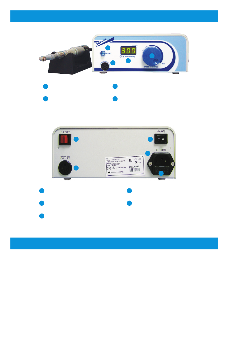
When this happens, the motor direction should be reversed by ipping the red switch
marked “forward and reverse” (this is located on the back of the unit) to reverse. This will
allow the hair to become untangled.
Samples of disposable prophy angles are included. These can be used in emergency
cases where the metal prophy head is not working. Additional disposable heads can be
purchased by calling 1.800.525.5614.
The polisher/micromotor can be modied to allow placement of diamond burrs or cutting
discs.
u
Diamond Burrs – J0452D8M
These require replacement of the prophy angle head with a contra angle head
(J045D9). The contra angle is placed on the straight hand piece just like the prophy
head. The burrs are inserted into the contra angle as outlined in their instructions.
u
Cutting Discs – J0452D7
The prophy head is removed and the diamond cutting disc is inserted directly into
the straight hand piece and locked in place.
Both the burrs and discs should run at higher RPMs to work eectively. Use caution
and work slowly when operating cutting instruments.

10
REGULAR MAINTENANCE
TECHNICAL SPECS
The polisher unit does not need special maintenance however it does need to be
regularly and thoroughly cleaned.
u
Daily Start-Up
When starting the unit at the beginning of the day, push the Main Power Switch.
NOTE: If digital display does not light, please contact Jorgensen Laboratories.
u
Daily Shut-O
When stopping the unit at the end of the day, push the Power Switch to turn the unit
o. The following suggestions are also useful in extending the product life of the unit.
uPlace the main unit in an open area where air can ow freely around it.
uWhen moving the main unit, handle with care.
uBefore leaving the room, make sure the AC power is turned o.
The J0453 unit is designed and manufactured to meet the most demanding environment.
Specications are listed below.
Classications
u
Class I
Type of protection against electric shock
u
Type BF
Degree of protection against electric shock
u
IP40
Degree of protection against the harmful ingress of water
Complies to Following Directive/Standards
u
ISO13485
Medical Devices (Quality Management Systems) - Requirements for regulatory
purposes.
u
EN60601-1
Medical Electrical Equipment - General requirement for safety
u
EN60601-1-2
Medical Electrical Equipment (Electromagnetic Compatibility) - Requirements and
tests.
Power Supply
u
115V±5%, 160VA
u
230V±5%, 160VA
u
~50/60Hz

11
OPTIONAL ACCESSORIES
The following dental items are also available from Jorgensen Laboratories.
SKU DESCRIPTION
J0452D4 Portable Water Tank
J0452D5 Polishing Paste - 100 Cups
J0452D3 Metal Prophy Angle
J0452D6 Rubber Prophy Cups - 100
J0452D7 Diamond Cutting Disc
J0452D8M Diamond Dental Burrs - 7
J0452D9 Contra Angle
J0452D10 Straight Hand Piece
J0452D13 Disposable Prophy Heads - 6 Pack

Jorgensen Laboratories, Inc. |Loveland, CO 80538
Professional Veterinary Equipment Supplier
Table of contents
Popular Dental Equipment manuals by other brands

GNATUS
GNATUS Autoclave Bioclave 12L owner's manual

Belmont
Belmont BELRAY II 097 installation instructions

ivory
ivory Neo Line SL411E Operation manual

KaVo
KaVo GENTLEsilence LUX 6500B Repair Procedure

DentalEZ
DentalEZ StarDental 430 SWL Torque quick start guide

Woodpecker
Woodpecker Endo Motor instruction manual

IP Division
IP Division IP Trimmer SQ instruction manual

Wassermann Dental-Maschinen
Wassermann Dental-Maschinen WSM-2 user manual

Vista
Vista phasor 408800 user manual

mectron
mectron Easyjet Pro Use and maintenance manual

DENTSPLY
DENTSPLY X-SMART Endo Motor Operation manual

EMS
EMS AIR-FLOW handy 3.0 Operation instructions