MANUAL INTERCEPTOR
Installation and Operating Instructions
Page 4
Provide cleanouts as necessary in the piping from the fixtures to the interceptor as
this area is subject to grease-laden wastewater which can congeal and cause
blockages.
It is recommended to use a separate grease interceptor for each commercial
dishwasher. Refer to the dishwasher specifications regarding discharge flowrate and
size the interceptor accordingly.
If the cover of the interceptor will be subject to loads greater than foot traffic, a unit
with a higher load capacity cover will need to be installed. Specify this option at time
of unit order.
If the grease interceptor is serving a source of high concentration levels (i.e. a fat
drippings tray in a rotisserie cooker), the grease must be diluted with water before
entering the pipeline leading to the interceptor.
CAUTION: Installation except as instructed, tested, and rated may result in
performance failure.
CAUTION: Please take proper precautions when installing these units. Many
models will require multiple people or machinery to position for installation.
Always consult local code requirements before installation.
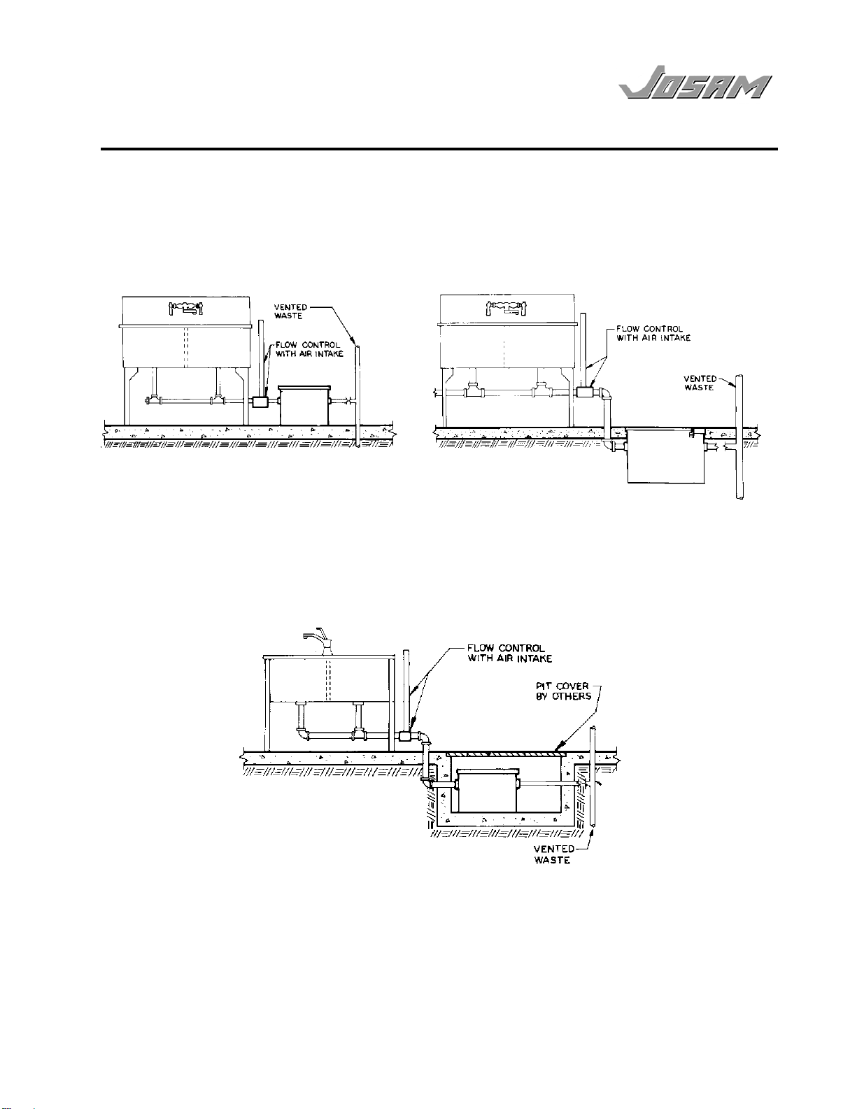
3.0 Flow Control and Venting
A flow control with air intake connection is supplied with each interceptor. This flow
control has been properly sized for this specific interceptor unit.
The orifice size and air intake are key components in a hydro-mechanical interceptor
design. Performance testing to industry standards and unit rating are dependent on
the use of the proper flow control and correct installation location.
The flow control should be placed after the last fixture being served and before the
grease interceptor. The air intake must be properly vented to allow air to mix with the
wastewater flow as it enters the interceptor to aid in grease separation.
The air intake may be connected to the vent stack if the fixtures themselves are
trapped and vented.
In order to prevent siphoning, the outlet of a grease interceptor must be vented.
Reference appropriate plumbing codes for venting requirements.