2
3. Specication
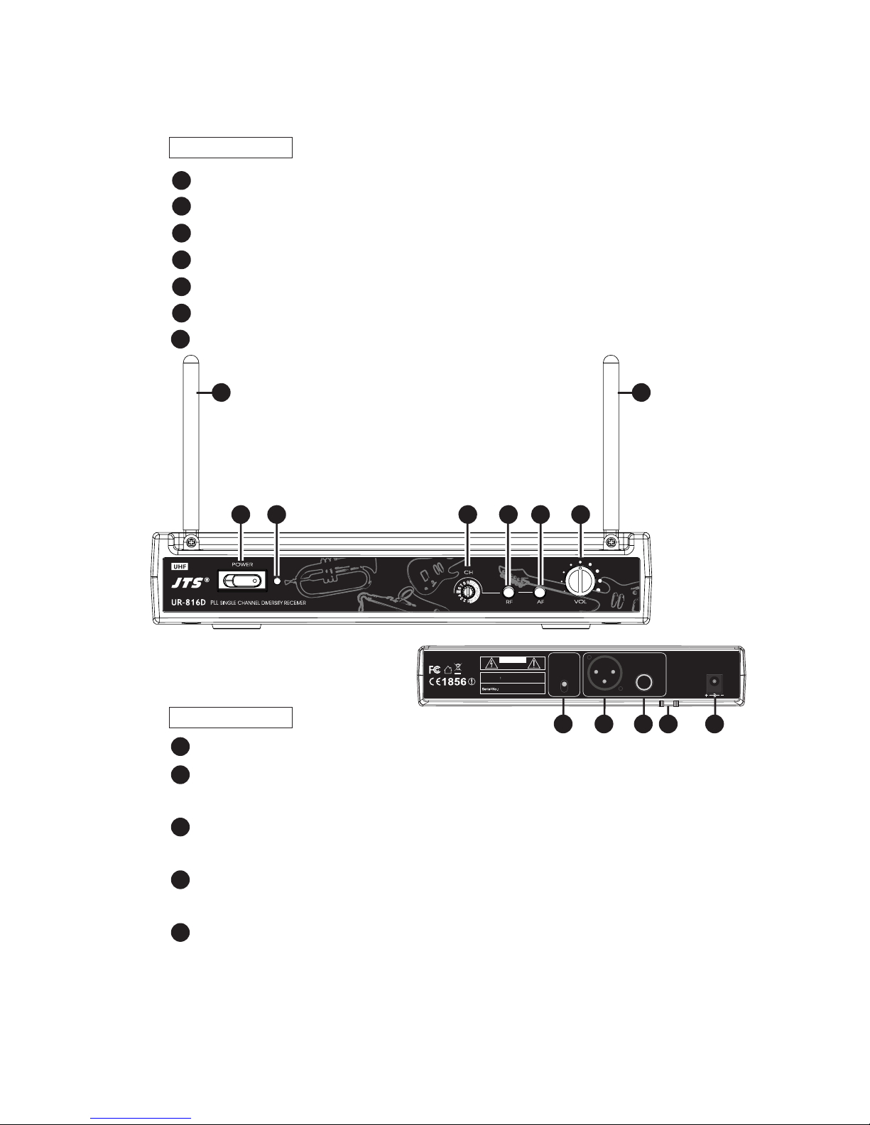
3-1 Receiver// UR-816D
3-2 Miniature Transmitter// UT-16GT
Frequency Preparation.........................
Carrier Frequency Range...................
S/N Ratio......................................................
T.H.D................................................................
Display..............................................................
Display Contents......................................
Controls..........................................................
Audio Output Level...............................
AF Output Impedance.........................
Squelch............................................................
Operation Voltage...................................
Output Connector..................................
Dimension(m/m)...................................
PLL Synthesized Control
502~960 MHz
> 105dB
<0.6%@1KHz
LED
Antenna A/B, RF/AF Status
Power On/O, Channel Selecting, Audio Level
-12dB
600Ω
Pilot Tone, Noise and Mute
12-18 VDC, 200mA
1 Balanced XLR socket
1 Unbalanced Ø6.3mm phone jack
221mm (W)* 40mm (H)* 152mm (D)
Frequency Preparation.........................
Carrier Frequency Range...................
RF Outputs..................................................
Stability............................................................
Frequency Deviation.............................
LED Display................................................
Controls.........................................................
Spurious Emissions................................
Audio Frequency Response ............
Baery..............................................................
PLL Synthesized Control
502~960 MHz
Maximum 10mW
±10KHz
±48KHz
Power On/O, Low baery, Mute
Power On/O, AF Level, Channel Selecting, Mute
<-50 dBC
40~18,000 Hz
LR03, AAA 1.5V*1