6189902 – Rev. C 07.2012
6
GB
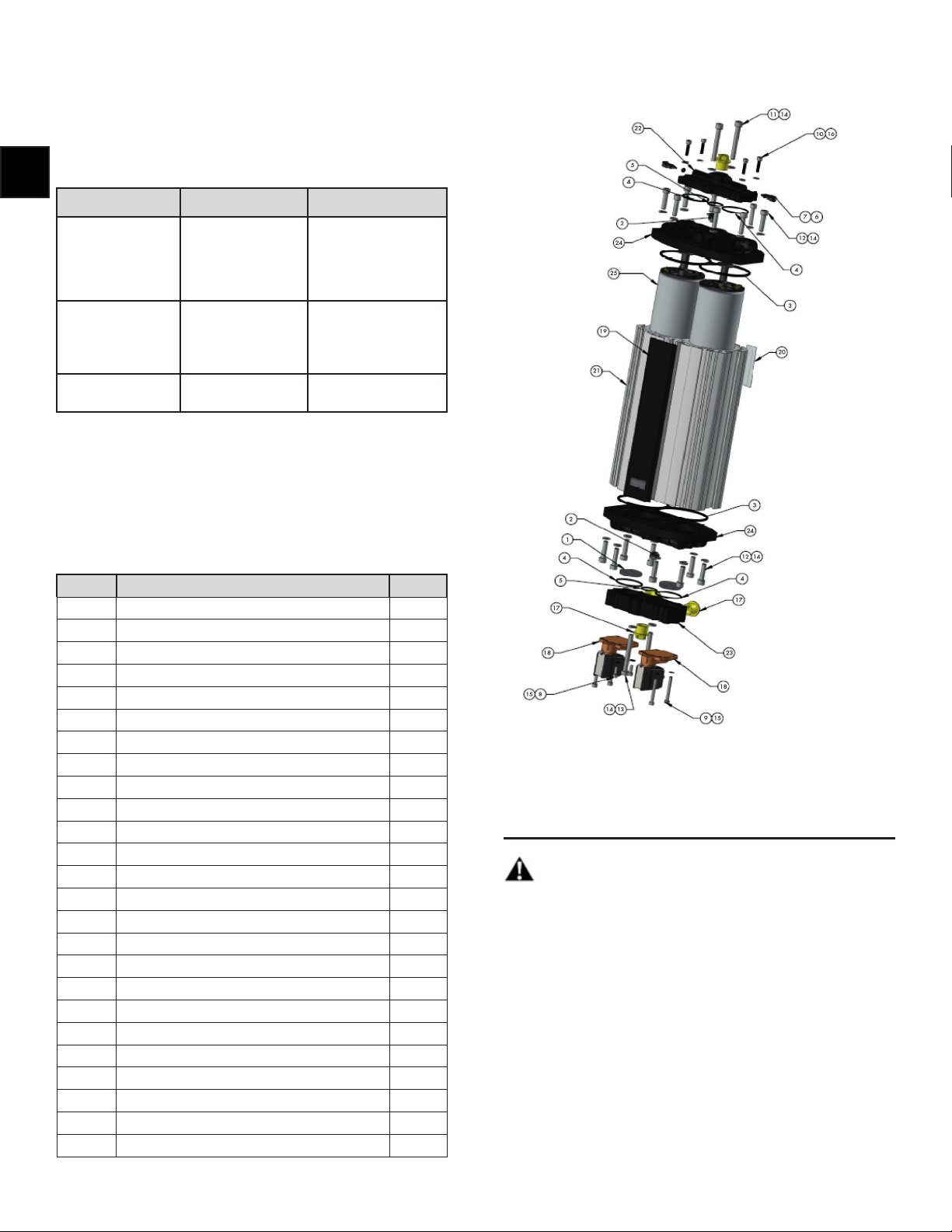
Replacement of top gasket seals, cartridges,
O-rings and valve ball:
Remove the 8(qty) M6x25 cap screws (12) and washers (14) as well
as the 2(qty) M6x50 cap screws (11) and washers in order to remove
the top common manifold (24).
Once these screws are removed, the top common manifold and the
outlet purge block (22) can be taken o the aluminum extrusion (21).
This will expose the dryer cartridges (25) which can be taken out of
the extrusion and replaced with the new cartridges.
The outlet purge block (22) can be taken o the top common
manifold (24) by removing the 4(qty) M4x18 screws (10). Once this
is removed, the valve ball (2) can be replaced as well as the 2(qty)
35mm o-rings (4) and 1(qty) 19mm o-ring (5). The gasket seal (3)
under the common manifold must also be replaced at this point.
Once all components are replaced, reassemble the common
manifold and the outlet purge block back.
NOTE: Torque all M6 bolts to 5 N.m and all M4 bolts to 3 N.m.
WARNING! Make sure that the dryer cartridges are installed
with the handle up for proper funconality.
IMPORTANT! Aer servicing the dryer, make sure to reset the
dryer service interval counter by depressing the rst 2 selecon
buons on the PLC for a minimum of 15 seconds.
Replacement of boom gasket seals, O-rings
and valve ball:
Note: Unscrew solenoid cables (not shown) from the solenoid valves
(18) before servicing the boom of the dryer. The ngs on the
valve block (23) need to be removed rst in order to remove the M6
cap head screws (12).
Remove the 8(qty) M6x25 cap screws (12) and washers (14) as well
as the 2(qty) M6x55 cap screws (13) and washers in order to remove
the boom common manifold (24) from the boom of the extrusion.
Remove the 4(qty) M4x35 cap head screws (9) and an-vibraon
washers (15) in order to take the valve block (23) o the common
manifold (24).
Once the valve block is removed, you can replace the boom valve
ball (2) as well as the 2(qty) 35mm o-rings (4) and 1(qty) 19mm
o-ring (5). The gasket seal (3) under the common manifold must also
be replaced at this point.
Once all components are replaced, reassemble the common
manifold and the valve block.
NOTE: Torque all M6 bolts to 5 N.m and all M4 bolts to 3 N.m.
Replacement of dryer solenoid valves:
If replacement of the dryer solenoids is needed at the me of seals,
o-ring and valve ball replacement, follow the same steps in the
replacement of the boom gasket seals, o-rings and valve ball with
the following addional steps:
Once the boom common manifold and the valve block are
disassembled, make sure to remove screws M4x12 cap head screws
(8) in addion to removing the M4x35 screws (9) in the valve block.
This will allow the solenoid valves (18) to be removed and replaced
with the new solenoid valves. Once the solenoid valves are changed,
reassemble the solenoids with the M4x12 and M4x35 screws onto
the valve block and the valve block onto the common manifold (24).
Finally aach the boom assembly to the extrusion with the M6x25
cap head screws (12) and the M6x55 (13) screws.
NOTE: Torque all M6 bolts to 5 N.m and all M4 bolts to 3 N.m.
WARNING! Make sure the dryer solenoids being replaced
have a voltage rang which matches the product label.
Service Intervals
The iQ-Dryer has a recommended service interval of 4,000 hours or
2 years whichever comes rst for the dryer cartridges, o-rings, and
valve balls. The actual life of the dryer may vary, depending on the
environmental condions.
The dryer solenoid valve(s) have a recommended service interval of
12,000 hours or 6 years.
2 Yrs 4 Yrs 6 Yrs 8 Yrs
4,000
Hrs
8,000
Hrs
12,000
Hrs
16,000
Hrs
Dryer
Service Kit XXXX
Solenoid
Service Kit X
Figure 6
NOTE: The drain bole should be emped every week.
Remove the cover on the drain bole by pressing in one of the two
tabs on either side.
Service Kits:
There are 2 types of service kits based on the items being replaced:
1. Dryer Service Kits.
2. Valve Service Kits.
1. Dryer Service Kits:
There are 3 dryer service kits based on the dryer size:
1. PN#: 4095000 – ADJ-050 (Q2) Dryer Service Kit.
2. PN#: 4095100 – ADJ-150 (Q3) Dryer Service Kit.
3. PN#: 4095200 – ADJ-300 (Q6) Dryer Service Kit.
The Dryer Service Kit includes:
Item # Part Descripon Qty
2 1/2” DIA 70 SHORE VITON BALL 2
3GASKET SEAL 2
4O-RING 1.78 Sec x 35 ID 4
5 O-RING 1.78 Sec x 19 ID 2
25 DRYER CARTRIDGE 2
- DRYER SERVICE MANUAL 1
Figure 7
2. Valve Service Kits:
There are 3 valve service kits based on the dryer solenoid valve voltage:
1. PN#: 4095010 – 24V DC, Valve Service Kit.
2. PN#: 4095020 – 110 VAC, Valve Service Kit.
3. PN#: 4095030 – 230 VAC, Valve Service Kit.
The Solenoid Valve Service Kit includes:
Item # Part Descripon Qty
8 M4 x 12 CAP HEAD SCREW 4
9 M4 x 35 CAP HEAD SCREW 4
15 M4 ANTI VIBRATION WASHER 8
18 SOLENOID VALVE 2
- VALVE KIT GUIDE 1
Figure 8