Jung FLW2200WW User manual

Radio performance unit
Radio Management
Radio performance unit
Art. No. : FWL2200WW
Operating instructions
1 Safety instructions
Electrical equipment may only be installed and fitted by electrically skilled persons.
Danger of electric shock. Always disconnect before carrying out work on the devise or
load. In so doing, take all the circuit breakers into account, which support dangerous
voltages to the device and or load.
Danger of electric shock. Device is not suitable for disconnection from supply voltage.
Serious injuries, fire or property damage possible. Please read and follow manual fully.
The radio communication takes place via a non-exclusively available transmission path,
and is therefore not suitable for safety-related applications, such as emergency stop and
emergency call.
These instructions are an integral part of the product, and must remain with the end
customer.
2 Device components
Figure 1
(1) Radio power pack
(2) red LED
(3) green LED
(4) Housing lid
(5) Screws
3 Function
System information
By statute, the transmitting power, the reception characteristics and the antenna cannot be
changed.
The range of a radio system from the transmitter to the receiver depends on various
circumstances.
1/9
32529813
J0082529813 02.11.2016

The range of the system can be optimised by selecting the optimal installation location, taking
into account the structural circumstances.
Figure 2: Reduced range due to structural obstacles
Intended use
- Radio-controlled switching of electrical loads for the duration of a settable time.
- Operation with suitable radio motion detectors, radio transmitters and installation buttons
as an extension
- Surface-mounted
Product characteristics
- Device responds to radio telegrams from radio motion detectors
- Operation possible via radio manual and wall transmitters
- Brightness threshold settable
- Switch-on time settable
- Switch-on for 2 hours and switch-off for 2 hours possible
- Can be integrated into All On and All Off
iCombination with radio presence detector possible, but without light control
4 Operation
Normal operation
In normal operation the power pack switches the load on for the set switch-on time when a
taught radio motion detector telegram is received. Switching-on takes place depending on the
brightness.
Taught radio hand transmitters, radio wall transmitter or installation buttons, NC contacts,
switch the load on the power pack independently of the brightness.
iSwitching on the mains voltage of the power pack always triggers a switching operation on
the power pack, regardless of the brightness setting.
The red LED (2) indicates the reception of a radio telegram and the green LED (3) indicates the
state of the switching output, see the next table.
red LED green LED
Receives radio telegram 1 second to No change
Battery of the motion detector
weak
on No change
Load is switched on No change on
Programming mode active flashes off
Transmitter taught on on
2/9
32529813
J0082529813 02.11.2016
Radio Management
Radio performance unit

Transmitter deleted on off
Switch-on for set switch-on time
oOperation with installation button: press push-button one time briefly.
Or:
oOperation with radio transmitter: Press taught channel button /\ less than 1 second.
The load is switched on for the preset switch-on time independently of the brightness.
Motion telegrams of a taught radio motion detector or radio presence detector are detected
and evaluated.
Switch on for 2 hours.
oOperation with installation button: press push-button twice briefly.
Or:
oOperation with radio transmitter: Press taught channel button /\ longer than 1 second.
The load is switched on for approx. 2 hours independently of the brightness. After that the
device switches back to normal operation.
Switch off the load
oPress the taught channel button \/ of a radio transmitter for less than 1 second.
Load switches off and device changes over to normal operation.
Switch-off for 2 hours
oOperation with installation button: press push-button three times briefly.
Or:
oOperation with radio transmitter: Press taught channel button \/ longer than 1 second.
The load is switched off continuously for approx. 2 hours. After that the device switches
back to normal operation.
All on
oPress the all on button of a taught radio transmitter.
All of the connected loads are switched on for the set switch-on time.
All off
oPress the all off button of a taught radio transmitter.
All of the connected loads are switched off.
5 Information for electrically skilled persons
5.1 Fitting and electrical connection
DANGER!
Electrical shock when live parts are touched.
Electrical shocks can be fatal.
Before working on the device, disconnect the power supply and cover up live
parts in the working environment.
Installing the power pack
Maintain a distance of at least 1 m between the radio transmitter and the power pack.
3/9
32529813
J0082529813 02.11.2016
Radio Management
Radio performance unit

Figure 3: Installing the power pack
oSlacken the two screws (5) and remove housing lid (4) (figure 1).
oIf necessary break out cable entry (8) for flush-mounted cable routing (figure 3).
oFasten power pack with two screws (6).
oRoute cables into the housing and connect to the terminals (7) (see Connecting the power
pack).
iThe power pack has double terminals for looping the connecting cables through.
oPut the housing lid on and fasten with the screws.
Connecting the power pack
The power pack can be connected in various ways.
oSelect the appropriate connection diagram depending on what installations are present.
Figure 4: Connecting the power pack
Each time the push-button (normally closed contact) is pressed, a switching operation of the
power pack is triggered (figure 4).
4/9
32529813
J0082529813 02.11.2016
Radio Management
Radio performance unit

Figure 5: Switching off the power pack
The power pack can be switched off using switch S1 or S2 (figure 5).
When the power pack is switched on again, switch S1 triggers a switching operation, while S2
does not.
Figure 6: Changeover switch
Changeover switches that are present can be replaced by push-button T, a normally closed
contact (figure 6).
5/9
32529813
J0082529813 02.11.2016
Radio Management
Radio performance unit

Figure 7: Automatic manual mode with two-circuit switch
S1 and S2 open: all off.
S1 closed, S2 open: normal automatic mode.
S1 and S2 closed: continuous light, manual mode, power pack without function (figure 7).
Figure 8: Connection in parallel with automatic staircase light switch / impulse relay
The lighting is switched on either by the automatic staircase light switch (9) or by the power
pack in combination with radio motion detectors (figure 8).
6/9
32529813
J0082529813 02.11.2016
Radio Management
Radio performance unit

5.2 Commissioning
Setting the brightness and switch-on time
Figure 9: Adjuster
(10) Brightness adjuster
(11) Switch-on time adjuster
(12) Rotary switch programming mode PROG
oSlacken the two screws (5) and remove housing lid (4) (figure 1).
oTurn brightness adjuster (10) to the desired value (figure 9).
Recommendation: A setting of 10 lux activates the device at the start of twilight.
oTurn switch-on time adjuster (11) to the desired value (figure 9). The switch-on time can be
set from approx. 10 seconds to approx. 15 minutes.
Teaching a radio transmitter
When teaching a radio transmitter, the sensitivity of the power pack is reduced to about 5 m.
The distance between the power pack and the transmitter being taught should therefore be
between 0.5 m and 5 m.
oSlacken the two screws (5) and remove housing lid (4) (figure 1).
oTurn rotary switch PROG (12) to ON to activate the programming mode (figure 9).
The red LED flashes.
oTrigger a teach telegram with the radio transmitter being taught (see instructions for radio
transmitter).
When the power pack receives the radio telegram, the green and red LEDs light up.
The connected load is switched on.
oTurn rotary switch PROG (12) to OFF to exit the programming mode.
The green and red LEDs go out.
The load is switched off, the power pack is in normal operation.
The radio transmitter has been taught.
iAfter a radio motion detector has been taught, it may still be in walking test mode, and
switches the lighting on briefly every time a motion is detected (see radio motion detector
instructions).
iIf all 30 memory slots of the power pack are occupied, a radio transmitter which has
already been taught must first be deleted.
7/9
32529813
J0082529813 02.11.2016
Radio Management
Radio performance unit

iWhen a radio transmitter is taught, All On and All Off buttons that are present are
automatically also taught.
Deleting radio transmitters
oTeach-in again the radio transmitter to be deleted.
6 Appendix
6.1 Technical data
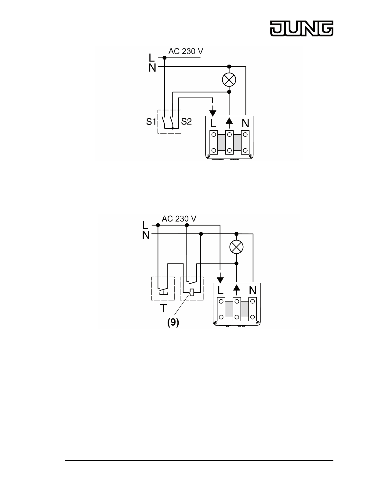
Rated voltage AC 230V~
Mains frequency 50 / 60Hz
Power consumption max. 2.5W
Ambient temperature -25 ... +55°C
Degree of protection IP 55
Circuit breaker max. 10A
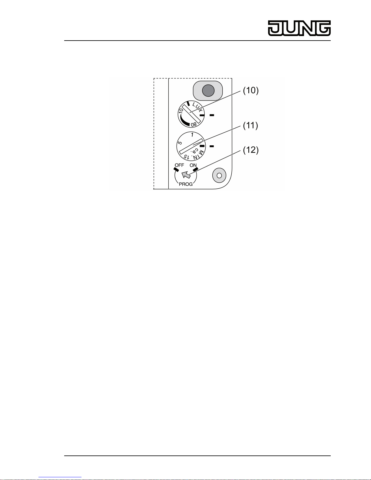
Switch-on time approx. 10s ... 15min (Retriggering)
Brightness setting approx. 3 ... 80lx
Switch-on current 20 ms max. 120A
Connected load
Incandescent lamps 2300W
HV halogen lamps 2300W
Inductive transformers 1000VA
Fluorescent lamps, uncompensated 1200VA
Fluorescent lamps, parallel compensated 920VA
Fluorescent lamps, duo circuit 2300VA
Connection
single stranded max. 4mm²
Fine-wire max. 2.5mm²
Finely stranded with conductor sleeve max. 2.5mm²
Radio frequency 433.05MHz ... 434.79MHz
Receiver category 2
Teachable radio transmitter max. 30
6.2 Troubleshooting
Load does not switch on, LEDs are off.
Cause 1: device has no mains voltage supply.
Connect device to mains voltage or check mains voltage supply.
Cause 2: no transmitters have been taught.
Teach transmitter (see section Teaching an radio transmitter).
Load does not switch on, LEDs indicate readiness for operation.
Cause 1: brightness is set too high when using radio motion detectors or radio presence
detectors.
Reduce brightness setting.
Cause 2: device is in the function "Switch-off for 2 hours".
Wait, or switch device on manually.
Device does not switch off after the set switch-on time.
Cause 1: device is in the function "Switch-on for 2 hours".
Wait, or switch device off manually.
Cause 2: There is a continuous heat motion in the detection field of a taught radio motion
detector or radio presence detector.
Eliminate the cause of the motion (see installation instructions in the appropriate manual).
8/9
32529813
J0082529813 02.11.2016
Radio Management
Radio performance unit

6.3 Conformity
Albrecht Jung GmbH & Co. KG hereby declares that the radio system type
Art. No. FWL2200WW
corresponds to the directive 2014/53/EU. You can find the full article number on the device. The
complete text of the EU Declaration of Conformity is available under the Internet address:
www.jung.de/ce
6.4 Warranty
The warranty follows about the specialty store in between the legal framework as provided for
by law.
ALBRECHT JUNG GMBH & CO. KG
Volmestraße 1
58579 Schalksmühle
GERMANY
Telefon: +49 2355 806-0
Telefax: +49 2355 806-204
www.jung.de
9/9
32529813
J0082529813 02.11.2016
Radio Management
Radio performance unit
Table of contents
Other Jung Radio manuals