Juwent UGW/D Series User manual

UGW/D
HEATING AND VENTILATION UNIT
Szymański, Nowakowski General Partnership
31 Lubelska Str., 08-500 Ryki
phone +48 81 883 56 00, fax +48 81 883 56 09
POLAND
I. CONTACTS
II. ORIGINAL INSTRUCTION MANUAL
III. WARRANTY TERMS AND CONDITIONS
IV. UNIT STARTUP REPORT
V. INSPECTION AND MAINTENANCE DOCUMENT
VI. SERVICE NOTIFICATION
VII. LIST OF SUBASSEMBLIES INSTALLED IN THE UNIT
Please read this instruction manual carefully before beginning any work.
RYKI 2013
ISSUE 1 EN

2www.juwent.com.pl
I. CONTACTS
Szymański, Nowakowski General Partnership
31 Lubelska Str., 08-500 Ryki
phone +48 81 883 56 00, fax +48 81 883 56 09
POLAND
Export department
mob.+48 502 087 841
mob.+48 664 465 243

3www.juwent.com.pl
II. ORIGINAL INSTRUCTION MANUAL
UGW/D HEATING AND VENTILATION UNITS
Size 10÷12

4www.juwent.com.pl
TABLE OF CONTENTS
1. INTENDED USE 5
2. DESIGNATIONS 5
3. OPIS URZĄDZENIA 5
4. TECHNICAL DATA 6
5. ADDITIONAL EQUIPMENT 7
6. TRANSPORT 8
7. SAFETY RECOMMENDATIONS 8
8. MOUNTING 9
9. WATER INSTALLATION 9
10. STEAM INSTALLATION 10
11. ELECTRICAL INSTALLATION 10
12. AUTOMATICS 12
13. DEVICE STARTUP 16
14. REPAIR, MAINTENANCE AND WITHDRAWAL FROM SERVICE 16
15. TROUBLESHOOTING 18
16. INFORMATION 18

5www.juwent.com.pl
1. INTENDED USE
UGW/D heating and ventilation units, size 10÷12, are intended to heat and ventilate such
compartment as:
»industrial halls
»warehouses
»workshops
»other objects of similar use
The units should be used only according to the intended use.
The manufacturer is not liable for using the units against the intended use and for any
damages arisen for this reason.
Heating and ventilation units cannot be used in the compartments with relative humidity
larger than 95% and air dust concentration over 5mg/m3.
The compartment can be served by one or larger number of the units, also by the units of different
sizes.
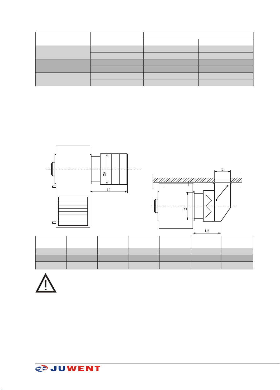
Units are suitable for mounting on walls at a height that allows direct air ow to the heated area.
Units are equipped with centrifugal fan allowing independent operation of the device or witch
attached additional equipment with air pressure drop up to 100 Pa.
The units can operate as heating units optionally with attached air lter at fan sucking side or as
heating and ventilation units with added intake boxes. The intake boxes enable to draw circulating
air, fresh air, or mixed in any proportion.
2. DESIGNATIONS
Heating and ventilation unit UGW/D- - - - - -
Size 10; 11; 12
Heating medium water (W); (oC);(MPa)
steam (P);(MPa)
Number of heating coil rows III, IV for water,
II, III for steam
Motor type
two speed three phase (TD);
single phase (J);
single speed three phase(T)
Speed 900/1400rpm, 1400rpm for size 10, 11
670 or 900 rpm for size 12
Type right (R) or left (L)
oC - heating medium temperature
MPa - permissible heating medium pressure
3. OPIS URZĄDZENIA
The unit consists of:
»highly efcient centrifugal fan in chemicals resistant version (1);
»water or steam heating coil (2);
All heating coils are made of bimetallic tubes i.e. steel core barrel and aluminium ribs rolled outside.
Standard water heating coils are made of tubes with the following dimensions: inner diameter
d=12,4mm, rib outer diameter D=38mm and ribs spacing 2,8mm and the steam heating coils are
made of tubes with d=21,4mm inner diameter, element outer diameter D=58mm and ribs spacing 5
mm. Connection spouts of the units with the steam and water heating coils are with threads.

6www.juwent.com.pl
For the bimetal water heaters the maximum temperature of heating medium is up to
150OC and the maximum operational pressure is up to 1,6Mpa.
For the steam heaters the maximum operational pressure is up to 0,6 Mpa.
There is a risk of heating medium freeze in the heater in the compartments with
the temperature below 0OC.
The risk can be reduced using an antifreeze thermostat (delivered at request), using antifreeze
heating media or removing water from the unit.
»casing (3) made of steel sheets with a single-row outlet grid allowing adjusting a direction of
supply air. The structure of grid blades protects against an automatic rearrangement of the blades.
The casing can be made of stainless steel sheets.
There are left or right types of units offered which means that with the right type the person looking
at the outlet grate sees the air intlet on the right.
4. TECHNICAL DATA
Basic dimensions
Unit size A
[mm]
B
[mm]
C
[mm]
D
[mm]
K
[mm]
L
[mm]
P
[mm]
Q
[mm]
a x b
[mm x mm]
h
[mm]
d Weight [kg]
water
steam
water III
water IV
steam II
steam III
UGW/D-10 519 945 373 345 291 260 563 90 295x400 385 ¾” ¾” 53 59 56 60
UGW/D-11 663 1245 479 410 342 342 794 116 390x520 490 1” 1” 87 96 78 95
UGW/D-12 808 1445 610 540 465 407 921 156 530x645 625 1¼” 1” 117 137 110 139
Unit environment and fan motor parameters
Unit size
Operation
temperature
[OC]
Max. air
humidity
[%]
Max. dust
content
[ mg/m3]
IP Insulating class
UGW/D-10,
11, 12 -15 ÷ +40OC95% 5 mg/m354 F

7www.juwent.com.pl
Units operational noise level
Unit size Speed
[rpm]
Noise level [dB(A)]
at the distance of 1m* at the distance of 5m*
UGW/D-10 900 59 55
1400 67 63
UGW/D-11 900 60 56
1400 70 66
UGW/D-12 670 62 58
900 68 64
*Level of operation noise - level of acoustic pressure with room absorbing capabilities A=100m2 and
directivity factor Q=2 taken into account.
5. ADDITIONAL EQUIPMENT
Air intake boxes SkCz/D
They are use for drawing of fresh and recirculation air or of their mixture at any proportion.
Air intake boxes are made of powder-coated steel sheets.
Air throttles could be controlled manually or by use of servomotors.
Filter section is equipped in net or air lter of G-2 class.
Unit size Box size D
[mm]
B
[mm]
E
[mm]
L1
[mm]
L2
[mm]
UGW/D-10 SkCz/D-10 345 340 157 436 269
UGW/D-11 SkCz/D-11 410 443 200 497 285
UGW/D-12 SkCz/D-12 540 570 240 497 285
When equipping the unit with intake boxes with lter:
- air capacity is reduced by ~10%;
- thermal powers are reduced by ~5%.
The air deriving boxes are offered in left and right types. The left type is used in left type units and
right type is used in the right type units.

8www.juwent.com.pl
6. TRANSPORT
The delivered units are completely assembled, protected from outside by polyethylene foil against
pollution and weather impacts.
The Product Manual is delivered along with the unit.
The intake boxes constitute additional equipment and they are delivered separately at the customer’s
request.
The automatics elements delivered at the customer’s request are packed separately.
The units should be transported in one layer in a way preventing mechanical damages.
7. SAFETY RECOMMENDATIONS
Solutions minimizing a possibility of hazard to persons and property were applied when
designing and manufacturing the units. However, it does not eliminate all possible risks.
The heating and ventilation units should be used only in compliance with the instruction
manual.
The start-up, mounting, connection, inspections and repairs of the unit should be
executed by an authorized installer, the electric works should be executed by a person
having required certicates authorized to carry out electric works.
All service and repair works should be executed when voltage is off.
In case of the unit failure it is necessary to switch off the power supply to the electric
motor of the fan and close the heating medium supply to the heater immediately.
The unit can be used only when electric safety devices operate correctly.
It must be permanently connected to the electric installation equipped with protective
(earth) terminal, residual current device and service switch.
It is necessary to pay attention not to change the protection lead to the power lead.
The operation of the unit with the fan without a protective net is forbidden.
The heaters of the units can be supplied with water or steam of very high temperature
(up to 160OC) what forces the users to be particularly carful.
A correct selection of ttings (including drain valves) by the designer of the installation
is a condition of safe operation of the steam heater.
Only original spare parts should be used.
Note for the user! The mounting or use of the heating and ventilation unit against the
instruction manual makes the threat of unit damage, creates the hazard to persons and
property and causes the loss of warranty.

9www.juwent.com.pl
Due to the structure the unit does not emit harmful radiation.
Although the unit was designed and manufactured in compliance with the requirements of the
standards, according to their state at the moment of production launch, a probability of injury or
health loss when using the unit is not to be avoided. This probability is connected with a frequency of
access to the unit in the course of its use, cleaning or repair, presence of persons within a dangerous
zone, acting against the safety rules specied in the instruction manual.
The gravity of body injury or deterioration of health condition depends on many factors that often
can be foreseen only partially, taking them into consideration in the structure of the unit, specifying
them and warning against them in the instruction manual.
Therefore there is a residual risk when the operator does not observe the recommendations and
guidelines included in the instruction manual.
8. MOUNTING
Hanging of the unit
For hanging the unit on the construction columns the catches are used (3 pcs) located at the rear
of the casing.
Unit size E
[mm]
F
[mm]
H
[mm]
UGW/D-10 240 28 760
UGW/D-11 345 28 1030
UGW/D-12 545 28 1180
Minimal distance of the heating unit from construction partitions at the unit sides is ~ 30 cm.
Hanging the units with intake boxes
Intake boxes should be screwed to the unit, the unit hanged on the wall and the intake box ange
screwed to the wall.
9. WATER INSTALLATION
Unit supply could be from top or lower spout. In new installations, better results are obtained with
lower spout supply due to the heater venting easier.
It is recommended:
»to use cut-off valves upstream and downstream the unit to enable its dismounting without
the necessity to drain the supply installation
»installation of the valve (recommended by Juwent) on medium supply spout.
The venting and draining of the heaters of the units is foreseen centrally in the network.
The vents and drain valves located in the installation outside the unit should be used.
The imprecise venting of the heater can be a reason for which the unit does not reach
planned parameters.
The weight of installation pipes should not rest on the spouts of the heater.

10 www.juwent.com.pl
When connecting the heater to the heating network the spouts of the heater should be protected
against breaking in a way presented in the picture.
The heater damages arisen for the afore-mentioned reason are not covered by the
warranty.
10. STEAM INSTALLATION
The steam heaters should be supplied from the top.
A correct selection of ttings (including drain valves) by the designer of the installation
is a condition of safe operation of the steam heater.
11. ELECTRICAL INSTALLATION
The electric installation and the connection of power to the unit must be executed
according to the relevant requirements of the standards and construction regulations.
The electric connections, start-up, inspections and electric repairs may be executed only
by an electrician who has required certicates to carry electric works and got acquainted
with the instruction manual.
Before the connection it is necessary to make sure whether the voltage value and power
system frequency are compliant with the data specied on the rating plates of the units.
In case of noncompliance the unit should not be connected.
The units are equipped with single (1~230 V/50 Hz) or three-phase (3~400 V/50 Hz). The units should
be powered from the main switchboard equipped with a main switch, differential protection device,
protective (earth) terminal and overload and short-circuit protection devices (motor switches). The
setup of overload protection cannot be higher than rated current of the motor (specied on the
rating plate of the motor of the unit).
The lack of required motor safety devices and non-connection of thermal contact TK to
the control circuit cause the loss of warranty.
The lead powering the motor of the fan should be inserted to the terminal box and fastened to the
protective supports by means of clamp bands.
Electrical connection of the motor must comply with the wiring diagrams placed in the terminal box.
Examples of wiring diagrams and control devices are given in Figures 1, 2 and 3.

11www.juwent.com.pl
Fig. 1. Example diagram of wiring and control of UGW/D units sizes 10, 11 with a two-speed three-
phase motor (connection Y / Y)
Fig. 2. Example diagram of wiring and control of UGW/D units size 12 with single-speed three-
phase motor (star connection only)

12 www.juwent.com.pl
Fig. 3. Example diagram of wiring and control of UGW/D units size 10, 11 with single phase motors
DIAGRAMS NOTATION:
PT – overcurrent motor protection K - Contactor
PZ – Control connecting button PW – Control disconnecting button
B - Fuses WS – service switch
12. AUTOMATICS
We can deliver for the units:
Supply and control boxes
The supply and control boxes (equipped with a main switch, overcurrent circuit breakers, short-
circuit protection devices, signalling lamps) are intended to cooperate and control the elements of
automatics, as above.
One control box allows controlling a group of the units by means of single thermostat.
The single (1~230V/50Hz) or three-phase (3~400V/50Hz) power supply of the supply and control
box should be from the main switchboard equipped with a main switch and differential protection
device.
When the automatics are ordered with the unit the electric diagrams of the unit and automatics are
delivered by the company as well.

13www.juwent.com.pl
WS Service switch
It is intended to switch off the fan motor in order to carry out service works. The use of the switch WS
prevents an unexpected activation of the motor that could cause the risk during the service works.
Type WS-3 WS-6
Main circuits: poles 3-pole 6-pole
Supply circuit switch 1- and 3-phase current 3-phase current
Rated continuous current 25A 25A
Protection rating IP 65 IP 65
Fig. 1. WS-3 Service switch (3-pole) Fig. 2. WS-6 Service switch (6-pole)
Three-way valves
The directional valves found a wide application in the units for the adjustment of heating medium
ow through the heaters. The valves should be installed in the supply line, the ow is admissible only
in the marked direction AB->A or AB->B.
Symbol DN kVS, m3/h t[OC] PN Unit type
V20 20 3,5 1...110 16 UGW/D-10
V25 25 5 1...110 16 UGW/D-11
UGW/D-12
FITTINGS:
Z: cut-off valve: manual
P: circulating pump
MV: three-way control valve controlled by
servomotor

14 www.juwent.com.pl
Valve servomotors
The servomotors that allow controlling the valves “continuous-0÷10V DC” (by means of controller
RT) or “on-off” (by means of thermostat TP or TPP) are used for a direct installation on the valves.
Therefore a position (protrusion) of the servomotor stem is proportional to the value of control
signal from the controller or thermostat.
Servomotor type on/off continuous
signal
Supply voltage 230V AC 24V AC
Closing / opening
time 180 s 150 s
Protection rating IP40 IP43
Fig. 3. Servomotor [on-off]
L-N Supply voltage 230V AC
Fig. 4. Servomotor [on-off]
N Supply voltage 230V AC
Y1 Control signal: open 230V
Y2 Control signal: close 230V
Room thermostat
A room thermostat (on-off) TP allows setting the required temperature in the room within the
range of 8...30OC by means of a knob, however, the room thermostat (on-off) TPP allows setting the
required temperature in the room within the range of 8...35OC in the day and night mode on the
liquid-crystal display.
The loss of temperature in the room below the set value causes that the thermostat applies a signal
to open the valves and switches on the fan. However, if the temperature in the room exceeds the set
value then the thermostat toggles itself applying a signal to close the valves and switches off the fan.
The thermostat can be used in the circulating and external air system.
TP or TP/IP65 thermostat
Supply voltage 24..250V AC 24..250V AC
Measurement range 8...+30OC8...+35OC
Contact rating 6(2)A 10(1,5)A
Protection rating IP30 IP65
TPP thermostat with time programmer
Supply voltage 2 batteries 1,5V
Measurement range 5...+35OC
Contact rating 5(2)A
Protection rating IP30
Fig. 5. Thermostat TP
L-Y1 Heating
L-Y2 Cooling
Fig. 6. Thermostat TPP
Q11-Q14 Heating
Q11-Q12 Cooling

15www.juwent.com.pl
Antifreeze thermostat
The heater protection system against freezing (antifreeze thermostat) is a recommended part of the
control system in the heating and ventilation units with the water heaters operating in the external
air system.
The thermostat has a capillary evenly unrolled along the eld of the heater that – after the reduction
of the air temperature (even on a short section of the capillary) below the boundary temperature
(5OC) – transmits a signal to the supply and control box which – to the thermostat response –
signalises the alarm state by the lamp “HEATER ALARM”, switches off the fan, closes the external
air throttle and opens completely the heating water valve of the heater. The system returns to the
normal operational mode automatically when the heater temperature is increased.
The antifreeze thermostat TPZ1W is used in the system with the room thermostat TP(TPP).
TPZ1 controller
Supply voltage 24...230V AC Fig. 7. Thermostat TPZ1
1-2 Freeze alarm
1-4 Normal operational mode
Measurement range -5...+15OC
Factory setting 5OC
Contact rating 10(2)A
Protection rating IP54
M Throttle servomotors
The servomotors whose task is to set the air throttle in the required position and to protect water
heaters against freezing are used to control external air throttles. Depending on a throttle control
method we use the servomotors of the following type:
»open/close “on-off”
»with continuous operation 0..10V. The setup of the throttle in the specied position is achieved
by applying the control voltage from the throttle ZW position controller of the value 0...10V.
Servomotor type on/off continuous signal
Supply voltage 230V AC 24V AC
Closing / opening
time 150 s 150 s
Protection rating IP54 IP54
Fig. 8. M throttle servomotor [on-off]
N Neutral 230V AC
Y1 Control signal: open 230V
Y2 Control signal: close 230V
Fig. 9. M Throttle servomotor - continuous signal
Y Input control signal 0…10V DC
G0 System zero
G Phase, 24V AC

16 www.juwent.com.pl
Temperature Controller
The indoor Temperature Controller shown in is used to preset room temperature within range
from 8OC up to 30OC. The controller compares the indoor temperature (measured by an integrated
sensor) with the preset value. In case of irregularities, the Controller generates a controlling signal
(constant: 0...10V DC) sent to the actuator of the heating valve.
Supply voltage 24V AC
G-G0 supply voltage 24V AC
Y1 valve control signal output, 0…10V DC
Measurement
range 8...+30OC
Output signal 0...10V DC
Protection level IP42
13. DEVICE STARTUP
Before start-up following should be done:
»check condition of the unit mounting,
»check water or steam connections tightness,
»check electrical power supply according to electrical board,
»check additional fan and unit casing protection,
»check correct connections to the motor,
»check fan direction of rotations.
To switch on the unit:
»open heat medium valves (steam supply valve should be opened gradually).
»switch on the power supply to the motor,
»adjust the direction and blown air range with use of the inlet grid blades,
To switch off the unit:
»restrict heat medium ow to the unit water heater (or cut off supply of the steam),
»switch off the power supply to the fan motor,
After a long period of standstill or in case of break in heat network operation the heaters
should be dewatered and the shut-off valves eventually closed.
14. REPAIR, MAINTENANCE AND WITHDRAWAL FROM SERVICE
The applied rolling bearings of the fan do not require a periodical lubrication. However, it is
recommended to check periodically a condition of the motor bearings (the rotor of the fan should
rotate freely without excessive backlashes and knocks).
When the noise level of the unit operation is increased it is necessary to check up the correctness of
fastenings of the fan and the whole unit (including the elements of additional equipment).
The rotor blades should be cleaned with a damp cloth after removing the protective net not to allow
unbalancing the rotor.
In case of any disturbances in the unit operation it is necessary to contact with the installer or the
service.
All maintenance and repair work should be done with disconnected power supply. The
unit should also be protected against accidental switching on by other persons.

17www.juwent.com.pl
The heater contamination state should be checked up periodically. The contaminated heater should
be blown through with compressed air.
The heater contamination reduces the air efciency and heating power of the unit.
Depending on the air pollution degree the lter contamination state in the intake box should be
checked up periodically. The contaminated lter should be cleaned (possible triple ltrating fabric
washing) or replaced with the G3 class fabric.
The contaminated lter reduces the air efciency and heating power of the unit.
After withdrawal from service the unit should be passed over to the specialized collection point of
recyclable materials.

18 www.juwent.com.pl
15. TROUBLESHOOTING
Trouble
description Possible trouble cause Troubleshooting
heat exchanger le-
akage
mechanical damage of heat exchanger (it may easy
appear when the unit is connected to the installation
without taking care
use a locking spanner to mount with the installation de-
nitely
exceedance of admissible heating medium para-
meters
connect the unit with the heating installation protected
against the excessive pressure and temperature growth
heat exchanger freeze
use an antifreeze thermostat, antifreeze heating uids or
remove water from the unit within the period of standstill
and freeze risk
use of the unit in the aggressive environment
too load operation
of the unit
minimum distance from the wall or ceiling is not
maintained use distances recommended in the instruction manual
improper revolution direction execute a proper electric connection
improper parameters of the mains use the unit only when the parameters of the mains and
the unit are compliant
air outlet is blocked by outlet grid louvres avoid a signicant closing of outlet grid louvres at high
speed ratios
fan vibrations, the blades rub against xed elements check up the correctness of the fan and fastening reliabi-
lity of other elements of the unit
not centric fastening of the fan in its bearing plate
fan does not work
incorrect or unreliable electric connections check up or correct:
1) compliance of electric connections according to the
diagrams specied in the instruction manual
2) reliability of connections on electric terminals
3) parameters of the mains
improper parameters of the mains (lack of three
phases in three-phase motors)
fan motor is damaged
fan operation control elements are damaged
Servomotor does
not open the valve
correctness of thermostat operation (characteristic
“tick” when switching)
check up or correct:
1) compliance of electric connections according to the dia-
grams specied in the instruction manual
2) reliability of connections on electric terminals
3) parameters of the mains
4) whether the servomotor reacts to an electric pulse. If
the servomotor damage is stated, the damaged element
should be claimed.
Room thermostat
does not apply the
signal
more than one unit is connected directly to the ther-
mostat (larger number means the thermostat over-
load)
check up or correct:
1) compliance of electric connections according to the dia-
grams specied in the instruction manual
2) reliability of connections on electric terminals
3) parameters of the mains
4) if there is no characteristic “tick”, the thermostat is me-
chanically damaged and should be claimed.
mounting place of the thermostat in the room
16. INFORMATION
As to all issues concerning the TERM heating and ventilation units please contact JUWENT Production
Plant or Representatives

19www.juwent.com.pl
III. WARRANTY TERMS AND CONDITIONS
1. JUWENT Szymański, Nowakowski General Partnership, headquartered in Ryki at 31 Lubelska Str., hereinafter referred to as the
Warrantor, grants the Customer a warranty of proper operation of the unit with reservation of the requirement of its use in accordance
with the conditions determined in the instruction manual and the terms and conditions specied below.
2. The warranty has been granted for a period of 24 months from the purchase date demonstrated in this warranty document with
a possibility of its special extension according to a separate agreement and specied in the Special Warranty Terms and Conditions.
3. The warranty covers the removal of technical defects of the unit arisen as a result of its use in accordance with the instruction
manual, revealed within the warranty period. The warranty provisions are valid in the territory of the Republic of Poland.
4. By virtue of the granted warranty the Warrantor is not liable for the loss of expected prots and costs resulting from a periodical
impossibility of the use of the unit incurred by the Customer.
5. To realize the Customer’s rights resulting from the warranty it is required to deliver the claimed unit with the warranty document
to the Warrantor at his expense.
6. The claimer delivers the unit in an original factory packing, in case there is no factory packing the claimed unit should be delive-
red by the Customer for the repair in a way ensuring a safe transport. The risk of accidental damage of the unit during the transport
burdens always the party that dispatches the parcel.
7. The defects revealed with the warranty period will be removed by the Warrantor free of charge. A method selection of the reali-
zation of obligations resulting from the warranty granted to the Customer belongs to the Warrantor that may remove a defect by the
repair or the replacement of the damaged subassembly or by the replacement of the unit. The property of the unit withdrawn from
service and / or defective subassemblies is transferred to the Warrantor.
8. The warranty is extended by a period for which the Customer has been deprived of a possibility to use the unit.
9. The Warrantor will make efforts that the repair is executed without further delay within the time-limit of up to 14 working days
from the delivery date of the unit. In reasonable cases of which the Customer will be informed by the Warrantor, this time-limit may
be extended, e.g. by the time of provision import or when there is a necessity to execute an expertise or laboratory tests in specialized
institutions.
10. The Warrantor is liable exclusively for the defects inherent in the sold unit. The damages arisen after its sale for other reasons are
not covered by the warranty, in particular:
a) mechanical damages (including also damages caused by microparticles occurring in the working environment of the unit),
thermal damages, chemical damages and aleatory damages or damages caused by the atmospheric factors,
b) damages occurred as a result of non-observance of typical rules or the rules required by the instruction manual related to the
operation and mounting of the unit or the use of the unit against the intended use and other damages caused by the Customer’s
activity or omission,
c) damages being a result of defective operation of the system in which the unit has been built or used,
d) damages occurred as a result of non-execution of the actions to which the Customer has been obliged in accordance with the
instruction manual, e.g. periodical cleaning, maintenance, adjustment, etc.,
e) damages occurred due to the use of materials or parts subject to a normal operational wear other than the materials recom-
mended by the Warrantor in the instruction manual,
f) damages being a result of use of power supply of the unit (of the system in which this unit functions) incompliant with the
standard, and in case the unit is also supplied with water, damages being a result of use of water (supply water and / or boiler
water) with parameters other than the parameters foreseen in the valid standard (PN-93/C-04607),
g) damages occurred as a result of operation and / or maintenance of the unit in a way incompliant with the instruction manual
and / or executed by the unauthorized persons.
11. The warranty does not cover as well:
a) activities executed by the Customer in accordance with the recommendations included the instruction manual of the unit within
the framework of normal maintenance and inspections,
b) travel and work costs of the Warrantor’s service or an entity delegated by the Warrantor in case when a warrant call turns out
to be groundless.
12. An annotation made by a trained employee in the Inspection and Maintenance Document of the unit is a conrmation of time-
-limit holding and range of activities foreseen for the maintenance of the unit.
13. The Warrantor is not liable for damages incurred by the Customer or third parties caused the run of the unit occurred in particular
as a result of non-observance of the afore-mentioned terms and conditions by the Customer.
14. In case the service works are executed by the Warrantor at the place where the unit is mounted, the Customer will make available
a free access to the rooms where the units are located to the Warrantor.
15. In case the units are mounted at the height making an access from the oor surface impossible, the Customer will ensure the
scaffolding compliant with the OHS regulations or mobile lifting platforms and vertical transport equipment.
16. The equipment from the electric and / or hydraulic system is disassembled by the Customer.
17. The claims should be lodged at the Warrantor’s address in writing / by fax / email using a service notication form.
18. The Warrantor refuses to execute the warranty activities (periodical service works or repair) in case the price for the unit or pre-
vious service work is not paid for the benet of the Warrantor.
DATE OF SALE STAMP AND SIGNATURE
Special Warranty Terms and Conditions:
Warranty period extension up to ........... months.
Other:
STAMP AND SIGNATURE

20 www.juwent.com.pl
TYPE OF UNIT:
FACTORY NUMER:
YEAR OF PRODUCTION:
IV. UNIT STARTUP REPORT
Date of
startup
Executor of startup
stamp / name and signature
Motor
current
[A]
User’s representative
stamp / name and signature Remarks
V. INSPECTION AND MAINTENANCE DOCUMENT
Date of
inspection
Executor of inspection
stamp / name and signature Service activity range Remarks
* Inspection of the unit in accordance with the section “Repair and Maintenance” in the instruction manual
This manual suits for next models
3
Table of contents
Other Juwent Fan manuals