JVA VM2 User manual

© JVA Technologies Pty Ltd Page 1 of 21 Issue:20/02/2020 9:36:00 PM
Vibration monitor manual.docx
VM2 Vibration Detection
Monitor
Product Manual
(Draft 7) Jan 2020
Contents
Instruction .....................................................................................................................................................................2
Scope............................................................................................................................................................................2
Limitations.....................................................................................................................................................................2
Standard System Components.....................................................................................................................................3
Sensor cable.................................................................................................................................................................3
Accessories...................................................................................................................................................................3
Features........................................................................................................................................................................7
Installation.....................................................................................................................................................................8
Cable Handling ...........................................................................................................................................................10
Tuning.........................................................................................................................................................................11
Operation....................................................................................................................................................................13
Programming Options.................................................................................................................................................16
Specifications..............................................................................................................................................................21

© JVA Technologies Pty Ltd Page 2 of 21 Issue:20/02/2020 9:36:00 PM
Vibration monitor manual.docx
Instruction
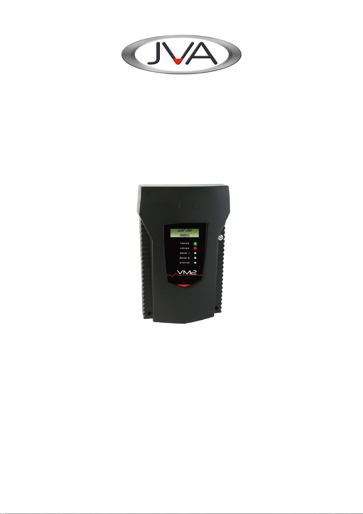
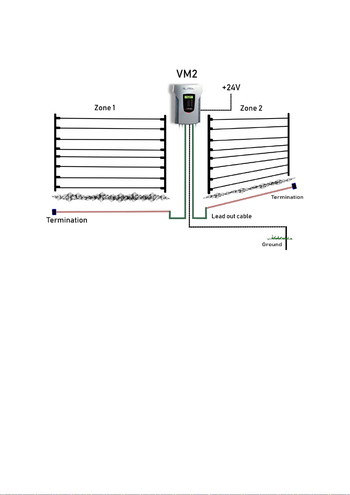
The JVA VM2 is a Perimeter Intrusion Detection System utilising Microphonic Cable. The VM2 (PTE0342) is
designed to monitor one or two zones of Microphonic (acoustic) cable to enable the detection of a breach of a
perimeter by detection of noise and vibrations created by unauthorised access or vandalism. The monitored cables
may be buried to detect digging, attached to a fence or placed inside a wall, roof or floor etc. to detect illegal
activity. The VM2, coupled with correctly installed cable creates fully monitored, zoned intrusion detection system.
The VM2 has adjustable threshold and time parameters to allow the installer to tune the system to differentiate
between an intrusion attempt and normal environmental sounds or vibrations. The VM2 complements JVA’s range
of security electric fence energisers and monitors. The VM2 is also compatible with the JVA Z-Series accessories
and software solutions. The VM2 comes with an inbuilt Wi-Fi Webserver which creates a professional Virtual
Keypad ™ for setup and control. A well as providing the features of a wired keypad, the Virtual Keypad ™ is
equivalent to both a user and an installer App, however it does not require any App to be downloaded.
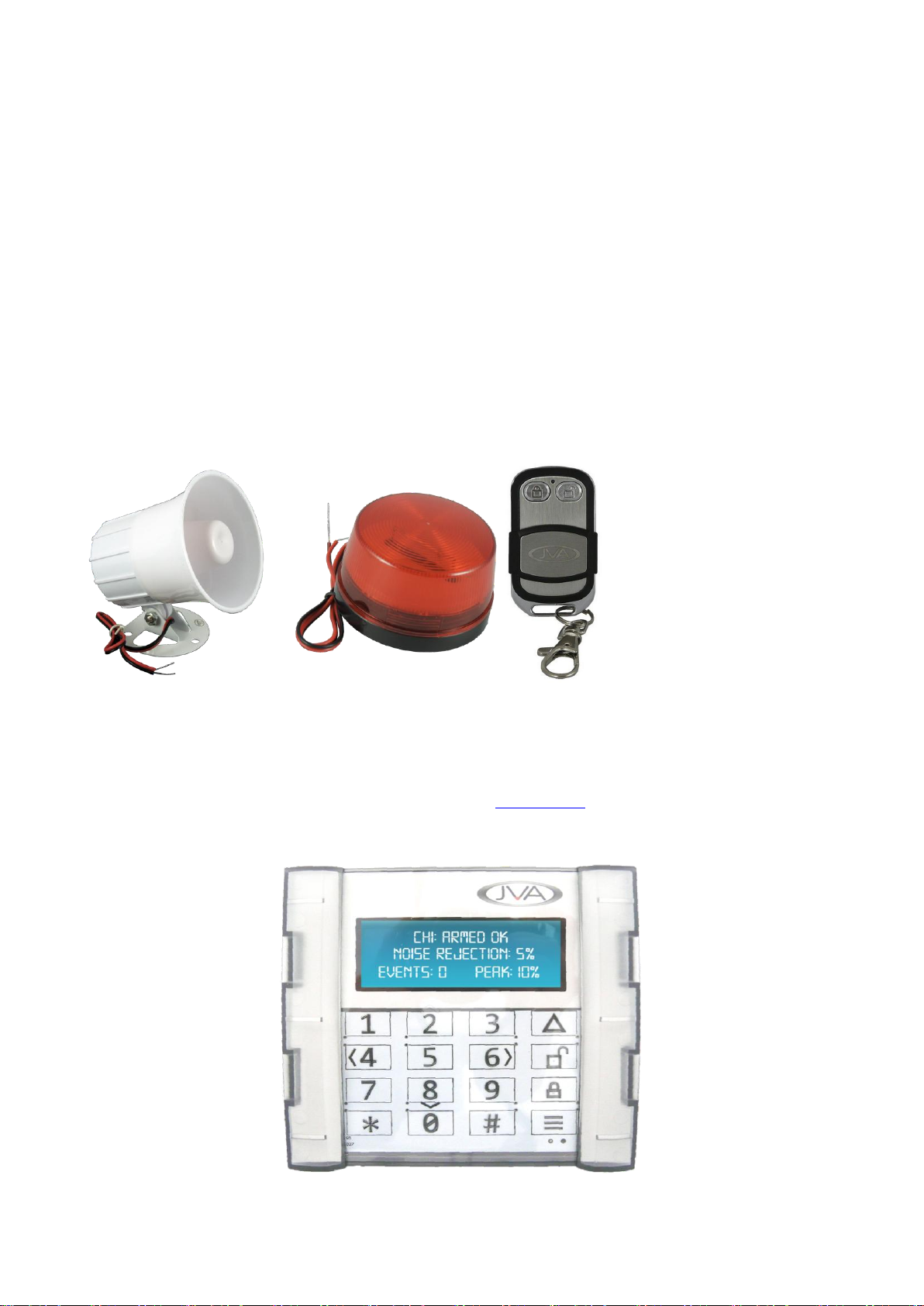
This unit can operate as a stand-alone alarm system through the addition of a Siren and Strobe; however the
addition of one of the optional user Interfaces makes the system more user friendly. These options include a 4-Line
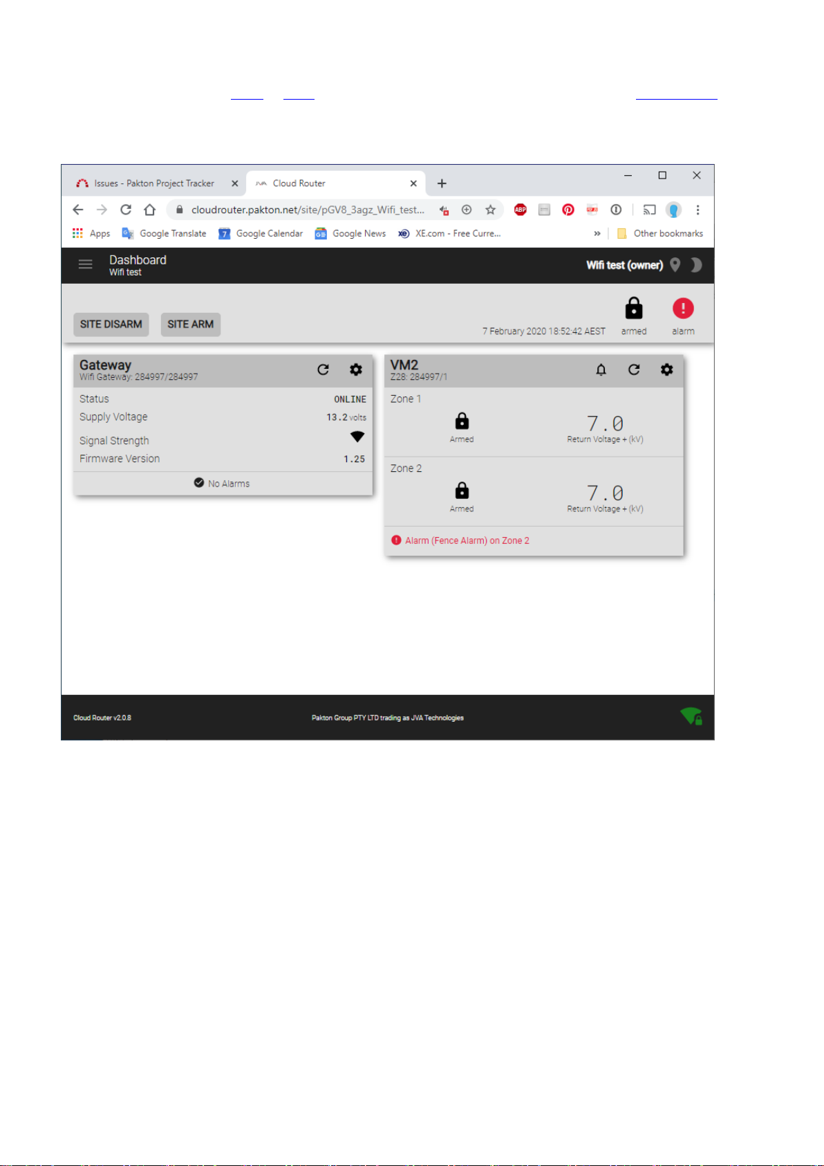
Keypad, Touch Keypad, Perimeter Patrol and the Cloud Router application.
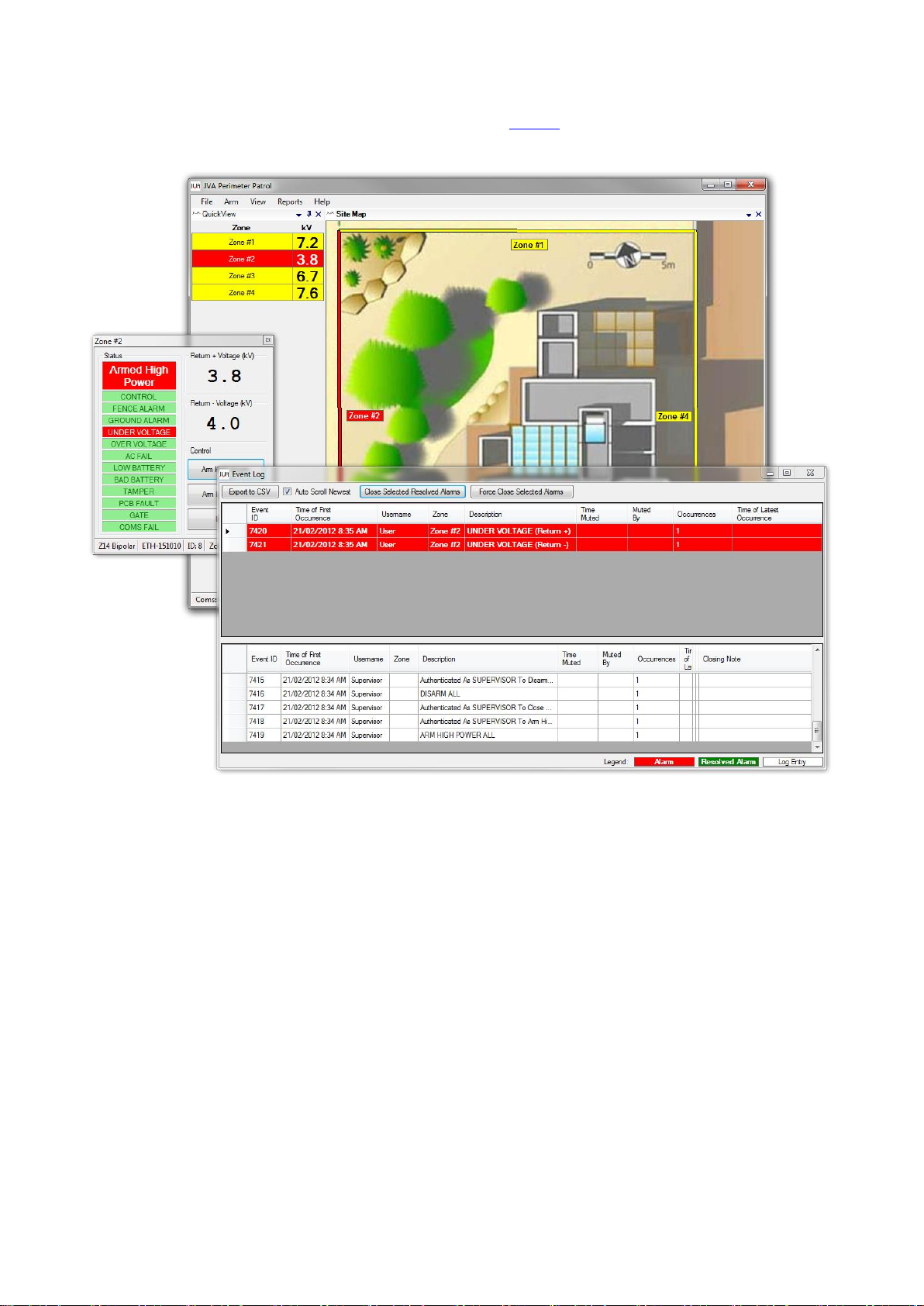
There are a variety of system integration options ranging from low level IO to a HLI based on JVA’s Perimeter
Patrol software.
Scope
This manual applies to the VM2 (PTE0342) PCB version 1.0, firmware version 1.0.
The latest manual can always be found online on the product guide page www.jva-fence.com.au/vm2 or the
general support page. https://www.jva-fence.com/downloads.php. (Draft note, these are coming soon).
Limitations
PCV 0v2. Firmware 1.0
At the time of writing the VM2 is in Beta Test stage and the following limitations applied.
1. 4-Line keypad is not yet compatible (VM2 emulates a 2 zone basic energiser for alarm reporting)
2. Touch keypad is not yet compatible
3. Perimeter Patrol is not yet compatible
4. Cloud Router is not yet compatible. Emulation will allow a VM2 to be monitored for alarms.
5. The inputs and output functions are fixed. Changes made using CLI or the Virtual Keypad will not change
the functions.

© JVA Technologies Pty Ltd Page 3 of 21 Issue:20/02/2020 9:36:00 PM
Vibration monitor manual.docx
Standard System Components
Draft Note: Show pictures of each of these:
The VM2
Sensor cable
Zone terminators
Cable joiners
Power supply
Sensor cable
The VM2 is compatible with JVA WR043 acoustic sensor cable.
Compatibility with other manufacturers cable has not been tested at this time, but it probably compatible with
AcousTek 10 and 20 and Senstar Mk1 and Mk2 cable.
Accessories
Accessories for standalone operation
Draft Note: Show a basic stand alone wiring diagram.
User Interfaces
4-Line Keypad
The 4-Line LCD keypad can arm and disarm the VM2. It can also display some of the more important running
information such as seen below. For more information see the support page.
Draft note, the 4-line is not yet compatible.

© JVA Technologies Pty Ltd Page 4 of 21 Issue:20/02/2020 9:36:00 PM
Vibration monitor manual.docx
Cloud Router
The VM2 can be linked to a Wi-Fi or GSM Cloud router gateway for control and monitoring via Cloud Router.
Draft notes: At time of printing the VM2 is only recognised when emulating a Z28. See below. The voltages are
fixed at 7.0kV (and are meaningless). The Alarms are live and it can be armed and disarmed.

© JVA Technologies Pty Ltd Page 5 of 21 Issue:20/02/2020 9:36:00 PM
Vibration monitor manual.docx
Touch Keypad
The Touch Keypad gives the most professional local user interface. It can also be configured to provide email
alerts and depending on the version, it may also provide a Cloud Router gateway function.
Draft note, the touch keypad is not compatible with the Beta test units.

© JVA Technologies Pty Ltd Page 6 of 21 Issue:20/02/2020 9:36:00 PM
Vibration monitor manual.docx
Perimeter Patrol
To connect a VM2 to Perimeter Patrol you will need a Keypad bus to USB adapter or a KPB to TCP/IP adaptor
(PTE0212). For more details on Perimeter Patrol please see the Manual.
Draft notes: 1) The Beta Units are not compatible.

© JVA Technologies Pty Ltd Page 7 of 21 Issue:20/02/2020 9:36:00 PM
Vibration monitor manual.docx
Features
Low priced
Compatible with Security Electric Fencing (can be used adjacent to or on the same fence)
Operates with:
oZ series keypads
oPerimeter Patrol
oCloud Router
Detects cut or shorted cables
Buried cable sensor system able to monitor two runs of up to 300m of active cable.
oDetects digging with any reasonable tool, shovel, pick, crowbar etc.
Able to be coupled (cable tied) to palisade or mesh fencing
oDetects cutting by a power tool
oDetects hammering or crowbar bending bars apart
Simple setup of sensitivity levels (Threshold, Event limit and Window)
Independent settings for each zone
On board Wi-Fi for
oVirtual Keypad ™ for programming
oCloud Router Gateway
LCD display
Z series Keypad Bus Mk2
IO (inputs and relays)
oArm 1, 2
oThree switched 12V outputs
oThree form C dry contact OR 12V switched relays
Battery charger for standalone operation
12 or 24V DC operation, low power requirements
Self diagnostics with on board LEDs for:
oWi-Fi status
oPCB Error
oCut or shorted cable
oEvents
oAll Power rails
oBattery Power
oSupply Power
oRelay functions

© JVA Technologies Pty Ltd Page 8 of 21 Issue:20/02/2020 9:36:00 PM
Vibration monitor manual.docx
Installation
It is recommended that all installations are performed by trained personnel. Training is available from JVA.
System elements and design
Installation Steps
1. Install the WR043 sensor cable. See section x on cable handling. Draft note not yet complete
2. Join standard RG59 cable to feed into your active zones, or to cross any areas where detection is not
required. Sealed cable joiners are available.
3. Join the WR024 cable from the fence to the VM2
4. Add a zone terminator (PTExxxx) to the end of each line
5. If using the internal back up battery, connect this before connecting 24Vdc. Note a battery is required if
you are going to run a siren and or strobes from the VM2.
6. Connect power to the VM2
7. Check the cable LEDs are showing as green (ok).
8. Connect to the VM2 Virtual Keypad (see section x)
9. Put the system into test mode and check it
10. Tune the threshold, event limit and window settings for your site to get the best balance between
sensitivity to attack and false alarms.
11. Perform a siren test
12. If using an internal backup battery, check the battery and AC fail by turning the 24Vdc supply off.
13. Create an alarm and check that the siren operates and that the User Interface(s) reports the alarm
correctly.

© JVA Technologies Pty Ltd Page 9 of 21 Issue:20/02/2020 9:36:00 PM
Vibration monitor manual.docx
Jumper Configuration
The VM2 is equipped with 9 jumpers. These are described in the table below.
Jumper
Function
Purpose
J3
Inhibit Mains fail error.
Fit J3 to inhibit Mains fail errors if the intention
is to operate the VM2 on DC only.
J4
Factory default jumper
Off to return programmable options to
factory defaults on power up.
If the energiser needs to returned to factory
default settings, remove all power (AC and
battery) and remove the J4 jumper. Reapply
the mains and the battery power. Reapply J4
jumper.
J9
Inhibit internal Beeper
Fitted to inhibit the internal beeper,
irrespective of any option setting.
J6,7,8
Powered outputs
Add these jumpers to apply power to the
common of the relay contacts for relays 3-5.
J2
Join channel 1-2 thresholds
Not applicable yet.
J10
Ch2 pull up
Not applicable yet. Linked out with PCB track.
J11, J12
Pad
Fitting a jumper to these lowers the zone
“gain”.
Vibration sensor cable connections
Connect the cable to the connectors on the left side of the front of the PCB as shown below.
NOTE: The earth must be connected to stop 50Hz mains noise from affecting the system.
Wiring and Indicators
USB
Power (+12Vdc)
Keypad Bus

© JVA Technologies Pty Ltd Page 10 of 21 Issue:20/02/2020 9:36:00 PM
Vibration monitor manual.docx
Example group wiring diagram
Cable Handling
This section contains information on how to make sure the sensor cable is not damaged in handling or installation.
It also shows how to and where to place the cable for best results for a number of typical applications.
Cable care.
Don’t kink it
Don’t knick the outer
Don’t let the core slide out
Don’t stretch or break the core
Joining and terminating the cable
The cable will need to be joined if you are using a non sensitive lead out cable. Such lead out MUST be coaxial
cable such as RG59, Do not use multi-core alarm cable, twin flex or Cat5/6 cable. Even though this system does
not use high frequency it is very sensitive to induced voltages from external sources such as 50Hz mains
electricity.
The conductors in the cable must remain insulated from the earth and any metal structure.
Use a weather proof junction box and standard double entry terminal strip, or a Gel filled cable joiner kit.
Do not run this cable in the same conduit as electric fence lead out cable.
Method for burying cable
The VM2 was designed primarily as an anti-dig sensor system. For best results bury the sensor cable in coarse
sand or gravel. Draft note: this section is not complete.

© JVA Technologies Pty Ltd Page 11 of 21 Issue:20/02/2020 9:36:00 PM
Vibration monitor manual.docx
Method for attaching cable to palisade or wire mesh fences
Draft note: Cable ties, Overlap of zones, Service Loops
Tuning
This section contains information on how to adjust the adjustable parameters to get the best balance between
sensitivity and false alarms.
The VM2 compares the sounds it picks up on the sensor cable to a preset limit called the Threshold. Any sound
that exceeds the adjustable Threshold is called an Event. If the number of Events in a preset Window of time,
exceed the Event Limit then that zone will go into alarm. An extra Event is counted if the signal exceeds the
threshold for longer than the Sample Time. This means that one long loud sound can create several Events. Note
that the front end of the VM2 is done in hardware not sampling software. This means it will not miss an event even
if the event is much smaller than the Sample Time.
The main parameters work in this way:
Parameter
Lowering this:
Raising this:
Threshold
Increase Sensitivity, generates more
Events
Reduces false alarms
Events Limit
Increase sensitivity
Reduces false alarms
Window
Reduces false alarms
Increases sensitivity
Sample Time
Increase sensitivity
Reduces false alarms
Test Mode
Put the VM2 into test mode, one zone at a time. Using the Virtual Keypad open the Device setup screen, you will
need the Installers PIN to do this, the default is 12345. Click on Test Mode for zone 1 and then 2.

© JVA Technologies Pty Ltd Page 12 of 21 Issue:20/02/2020 9:36:00 PM
Vibration monitor manual.docx
Assuming the cable is attached and properly terminated (the Cable status LED is Green). The LCD will show the
Peak and Average sound recorded and the number of recorded events in each window of time as currently set.
The alarms will not be latched and the siren will not sound. If there is an “Alarm” the number on the LCD will
increment.
Assuming there is a quiet environment what you are seeing on the screen is now your base line measurements.
Hopefully the sound % figures are low and there are no events.
If you have an average level of over 50% something may be wrong. Check that the earth terminal on the VM2 is
connected to a cabinet or site earth. If you cannot reduce this level consider purchasing or borrowing a phone
audio adaptor and recording the sound on this zone onto your phone or laptop. See later section on Recording
using a phone. Draft Note, add this. You may also consider reducing the overall sensitivity of this zone using the
Pad jumper.
If your cable is accessible you can check it is “live” by tapping on the sensor cable. Tapping with a pen should
create a peak of close to 100% and some events and an eventually an alarm.
Create the sounds of an intrusion on your fence or boundary and measure these. You will need someone standing
by the VM2 watching (or recording it with a phone camera).
For a false alarm free system, the sound levels for intrusion events must be much higher than your base level
(normal) sound levels.
Set the zone Threshold above the base level and below the intrusion peak sound level.
Leave the Window setting where it is. Reduce the Events Limit until you are happy that an intrusion sound will
cause an Alarm.
If you change the settings for Threshold, Events Limit or Window, re-enter test mode and check that an intrusion
sound causes an alarm.
Draft note we will need to create some diagrams to make this process easier, or perhaps some videos.
Repeat for the second zone.
Pad
If all the noise levels are too high (the system is too sensitive) you may engage the Pad on this zone (place a
jumper on the Pad pins J11 or J12) to reduce the amplification level (gain) on that zone.
Recording sounds for analysis
The VM2 has an audio output terminal on the PCB. JVA can supply a 3.5mm stereo to 3.5mm headphone cable to
allow you to connect to a smart phone to record the sounds as “heard” by the VM2. You can use any MP3 sound
recording App to do this. Play it back on your phone to make sure the recording has worked.
Send this file to us and we can analyse it for you.
Note: The equipment you use to record the sound should be isolated, i.e. NOT connected in any way to earth. An
Android or Iphone is perfect. A laptop may be used, so long as it is not plugged in to power.
Draft note this is not working on the V0.2 Beta samples.

© JVA Technologies Pty Ltd Page 13 of 21 Issue:20/02/2020 9:36:00 PM
Vibration monitor manual.docx
Operation
Display LEDs
The LED’s on the VM2 Display PCB allow for easy diagnostics while installing the system.
Power
-
On (Green) whenever the unit has power
Armed
-
On (Red) when the unit is armed, flashing for partial armed (1 zone)
Zone 1
-
On when there is a zone 1 alarm, short flash for an event
Zone 2
-
On when there is a zone 2 alarm, short flash for an event
Status
-
Used to flash error codes, see the table below
Error Codes
1 Tamper
2 AC Fail
3 Low Battery
4 PCB Error –see LCD for more information
LCD display
The LCD display shows the status of the VM2 at all times.
Diagnostic LEDs
The VM2 has several diagnostics LEDs visible when the lid is removed.
XBee Status
-
Shows Wi-Fi status see table ??
D22
-
Battery (12V) power present
Status
-
Same as Display LED status
D2
-
3V3 rail present
D1
-
Excitation present
D21 –D27
-
Relay 4 to 6 status
D28
-
24V power present
Cable ok LEDs
-
Green if cable is connected, terminated and not shorted
Event LEDs
-
Red when an Event has been detected

© JVA Technologies Pty Ltd Page 14 of 21 Issue:20/02/2020 9:36:00 PM
Vibration monitor manual.docx
VM2 LCD Screen
The VM2 will show the status on the LCD display.
When Armed
While armed, the LCD display cycles the following information.
Peak: means peak noise recorded in the last window of time.
Avg: means the average noise level.
Ev’s: means the events counted in the last window of time.
When an alarm occurs the screen will detail the type of alarm and the sector if applicable.
Various “troubles” are also displayed, such as AC fail or low battery.
When the VM2 is disarmed, any latched alarms are shown.

© JVA Technologies Pty Ltd Page 15 of 21 Issue:20/02/2020 9:36:00 PM
Vibration monitor manual.docx
Keypad Control
The VM2 contains a Virtual Keypad ™. You can use any Wi-Fi enabled device with a browser to access this. See
section x. While mainly designed for configuration the Virtual Keypad ™ may also be used to arm and disarm the
VM2.
The VM2 is compatible with the PTE0240 4-Line LCD and the PTE0230 Android keypad.
Compatibility
If you need to connect this device to a JVA keypad or Perimeter Patrol Software that pre-dates the release of
updates that support this device, you will need to turn emulation on. See options in section ?.
With emulation on the VM2 will appear on the keypad as a generic 2 channel electric fence energiser. The fence
voltage will always who as 0kV. The Zone 1, 2 and gate alarms will display properly as will the warnings such as
ac-fail and low battery. The keypad will be able to arm and disarm the VM2 zones. Programming with a non
compatible keypad will not work, use the Virtual Keypad ™.
To Arm/Disarm the VM2
You may use the control inputs (In1, In2), a keypad, a RF remote control, or one of the JVA software solutions
(Perimeter Patrol or Cloud Router) to arm and disarm the VM2.
When an Alarm Occurs
An Alarm will occur if any of the Zones goes into fault (triggers) while the Zone is armed. If attached, the siren will
sound and the zone strobe will light. This alarm will be indicated on any connected User interface.
The siren will cycle on and off based on the VM2 programming options. The strobe will remain on even after the
VM2 is disarmed. This will turn off when the VM2 is either re-armed, or a User Interface switches it off.
To Silence the Alarm
If there is no Keypad attached simply disarm the VM2 to silence the siren.

© JVA Technologies Pty Ltd Page 16 of 21 Issue:20/02/2020 9:36:00 PM
Vibration monitor manual.docx
Backup Power
The VM2 may be fitted with a 12V battery inside the case for backup power in case of mains fail. As the VM2 draws
very little power (see section x specifications) a standard 7.5aH battery will last much longer than 8 hours.
Programming Options
Default Installer PIN
12345
The VM2 has non-volatile memory in which programming options (or setup parameters) can be stored. These are
factory pre-set (defaults), but can be field programmed using a JVA 4 Line keypad or the Virtual Keypad ™.
Programmable Options Table
Option
Function
Default
Description
01
Group ID
1
If used as part of a group, this sets the device ID.
02
Zone 1
Threshold
25%
Sets a limit above which a sound is considered an Event worth
counting.
03
Zone 2
Threshold
25%
As above
04
Zone 1 Events
limit
5
The number of times a sound must exceed the threshold,
within the Window time, to cause an alarm
05
Zone 2 Events
5
As above
06
Zone 1 Window
30
A moving window of time over which Events are counted to
see if they exceed the Events setting. 30 = 3.0 seconds
07
Zone 2 Window
30
As above
08
Zone 1 Squelch
Off
Squelch reduces the effect of any constant noise i.e. 50Hz
hum
09
Zone 2 Squelch
Off
As above
10
Sample Time
10
Time in mS that we sample the comparators to check for an
event. NOTE we may lock this off from the users.
11
Spare
12
Battery Charger
Float Voltage
137
Battery float setting at 25C.
13
Low Battery
Level
110
90-135 (9.0V –13.5V) Low battery level below which a low
battery event is triggered. Do not enter the decimal point.
14
Wi-Fi Enable
1 (On)
15
Monitor Type
Not used yet
16
Emulation
1 (On)
Emulate a simple 2 channel energiser for compatibility with old
devices
17
Fire Cycle Time
13
13 = 1.3 seconds. If the VM2 is a slave this is not used.
18
Sectors
Not used yet
19
Spare
20
Input 1 Function
Arm Zone 1
Input 1 function (see table xx)
21
Input 2 Function
Arm Zone 2
Input 2 function
22
Input 1 Type
Input 1 Hardware type (see table xx)
23
Input 2 Type
Input 2 Hardware type
24
Alarm Delay
3
Delay from cable fault to alarm in seconds
25
Entry Delay
Not used yet
26
Exit Delay
Not used yet
27
Siren On Time
4
Sets the time that the siren (and keypad beeper) will stay on
after an alarm
28
Siren Off Time
4
The amount of time the siren will be off after the on time has
expired
29
Siren Cycles
3
The number of times the siren will sound for the time set in on
time above. After this many cycles the siren will automatically

© JVA Technologies Pty Ltd Page 17 of 21 Issue:20/02/2020 9:36:00 PM
Vibration monitor manual.docx
mute
30
Chime Mode
As per Z series, allows the keypad beeper to be used as a
door chime or siren etc.
31
Auto Rearm
Time
0
Sets the time which must elapse after an alarm has timed out
(completed the siren cycles) before the unit will automatically
re-arm ready for the next alarm event.
32
Relay 1
Strobe 1
Used to assign an alarm function to relay 1 (siren output)
33
Relay 2
Strobe 2
34
Relay 3
Siren
Not on PCB 0v2
35
Relay 4
Armed
Either zone armed
36
Relay 5
Alarm
Either zone in alarm
37
Relay 6
General
PCB error
Draft Note: There are a number of other system settings that we will leave fixed (and hidden) for now:
Filter Order. This sets the reaction time of the squelch which comes from the long term filter of the peak
signal. Set to 5 (Filter time const approx 2^5 * Sample time).

© JVA Technologies Pty Ltd Page 18 of 21 Issue:20/02/2020 9:36:00 PM
Vibration monitor manual.docx
Programming Options in Detail
See the programming options table above. Programmable Options are also known as Configuration or Setup. The
default settings have been chosen to be useful for a “normal” site. If you need to return the unit to default settings
see below (Return to Defaults).
Group ID
A group of Z series devices connect on a wired Keypad Bus must have only 1 master. The other
Energisers/Monitors in the group are slaves. The VM2 should be a master only if it is not in a group with Z series
energisers or monitors. I.e. if it is in a group the VM2 should be a slave.
If a PAE212 TCP/IP adaptor is used, it is the group master. All other devices should be set to slaves.
The VM2 defaults to a master (ID=1) so that it will operate correctly with a Keypad or Gateway.
Threshold (1 and 2).
If the VM2 detects a peak noise over this level it will
register an event. This should be set above the
normal background noise level on your site. This is
often the only setting that will need to be adjusted on
a typical site.
Events Limit (1 and 2)
If there are more than this number of Events
in a single Window of time, then there will be
an alarm. Increase this to reduce false
alarms. Adjust Threshold before changing
this setting.
Window (1 and 2)
This setting determines the amount of time in the moving Window used to count Events. This means that 5 events
spread over a long period will not trigger an alarm. Five events in rapid succession (within the one Window) will
trigger an alarm if the Events Limit is below 5. Reduce this to reduce false alarms. Adjust Threshold before
changing this setting.
DNY (Squelch 1 and 2)
This is not used yet.

© JVA Technologies Pty Ltd Page 19 of 21 Issue:20/02/2020 9:36:00 PM
Vibration monitor manual.docx
Sample Time
This setting can be used to reduce the number
of Events that occur from a single strike to a
fence. This is usually the last setting to adjust of
all those above.
Battery Float Set
The VM2 contains an inbuilt battery charger for a standby 12V lead acid battery. If you are not using the battery
ignore this setting.
This setting adjusts the voltage at which a lead acid battery will be charged and held at when fully charged. Please
consult your battery manufacturers specifications for the correct value.
If power outages are frequent use the recommended cyclic value; typically 14.7V.
If power outages are rare use the standby value; typically 13.7V
Raising this setting will NOT increase the speed at which a flat battery is charged. Setting it too high will damage
the battery.
Note that the temperature of the PCB is used to adjust this value. This assumes a lead acid battery type.
If you are measuring the float voltage at the battery leads using a multimeter, you must do this within 10 minutes of
power up, otherwise the controller will determine that there is no battery connected and show an alarm.
Low Battery Level
Low battery level below which a low battery event is triggered.
Set this to less than 130 (13.0V). Default setting is 110 (11.0V). The Low Battery Alarm will clear when the supply
has increased to 1.0V above the Low Battery Level.
Wi-Fi Enable
Turn this off if you are not using the Virtual Keypad ™. If you wish to secure the virtual keypad, change the WiFi
password using the Virtual Keypad instead.
If you turn this off, you will NOT be able to use the Virtual Keypad ™.
Fire Cycle Time
Not Used.
Input Functions
The defaults are:
Input 1- Arm Zone 1
Input 2- Arm Zone 2
Input Types
The defaults are normally open dry contact.
Alarm Delay (Cable fault alarms)
This sets the amount of time between a cable fault and an alarm. The default is 3 seconds.
Entry Delay
0-255 Seconds of Entry/Gate Delay. Only applicable if an input is set to a Gate input or a general entry zone input.

© JVA Technologies Pty Ltd Page 20 of 21 Issue:20/02/2020 9:36:00 PM
Vibration monitor manual.docx
Exit Delay
0-255 Seconds of Exit Delay. Only applicable if an input is set to a general exit alarm zone input.
Siren on Time
This option sets the duration of time that the siren will remain on after a fence alarm occurs. After this time the siren
will turn off for the Siren Off Time indicated in the table. The siren will sound again if the alarm is still present after
this off time has passed.
The default is 3 Minutes. This may be the subject of local regulations to stop an alarm causing undue
disturbance to neighbours, etc.
Draft note: None of the siren features are work on the Beta Test units
Note: the siren on time will be cut short if the battery falls below the low
Battery level.
Siren Off Time
This option sets the amount of time the siren will be off for after the Siren On Time has expired. If an alarm is still
present after this off time the siren will sound again.
Siren Cycles
This option sets the maximum number of times the siren will sound for the “on time” if the alarm continues. This
may be limited by local regulations to stop an alarm causing undue disturbance to neighbours etc.
Note: This is the maximum number of cycles for 1 continuous alarm, intermittent alarm events could cause more
than this number of siren soundings.
Chime mode
Draft note complete this.
Auto Re-Arm time
This option sets the time which must elapse before another alarm will sound after the first alarm has timed out
(gone completely through its cycles).
If an event occurs which triggers the siren, any other events which would otherwise trigger the siren (such as a
gate alarm) will be ignored while the siren is sounding and until after the Auto re-arm time has passed.
The default is 0 Seconds (Immediate).
Relay Functions
All relays can be set to any of the available functions (user assignable).
The defaults for the VM2 are:
Relay 1 –Strobe 1
Relay 2 –Strobe 2
Relay 3 –Siren (The 0V2 PCB did not have this output)
Relay 4 –Armed (or partially armed)
Relay 5 –Any Zone Alarm
Relay 6 –General Alarm
Return to Factory Defaults
At some point, you may want to return the VM2 to Factory Defaults. To do this remove all power from the VM2.
Remove J4, reapply power and replace J4.
Other manuals for VM2
1
Table of contents
Other JVA Monitor manuals