JVC KY-F550 User manual

KY-F550
COLOR VIDEO CAMERA
INSTRUCTIONS
For Customer Use:
Enter below the Serial No. which is
located on the bottom of cabinet. Retain
this information for future reference.
Model No. KY-F550U
Serial No.
Thank you for purchasing this JVC product.
Before operating this unit, please read the
instructions carefully to ensure the best
possible performance.
This instruction manual is made from 100%
recycled paper.
*Illustration with optional lens attachment.
LWT0158-001B

SAFETY PRECAUTIONS
FOR USA AND CANADA
This symbol indicates type B equip-
ment classified in accordance with
IEC Publication. 60601-1 Safety of
medical electrical equipment.
®
MEDICAL ELECTRICAL EQUIPMENT
WITH RESPECT TO ELECTRICAL SHOCK, FIRE AND
MECHANICAL HAZARDS ONLY
IN ACCORDANCE WITH
UL.60601-1, CAN/CSA C22.2 NO.601.1
56PA
AA-P700MD AC Adaptor is designed to use in Hos-
pital or other Medical usage.
AA-P700 AC Adaptor is designed to use for non
Medical usage.
Please use for appropriate AC Adaptor for your sys-
tem.
The use of ACCESSORY equipment not complying
with the equivalent safety requirements of this equip-
ment may lead to a reduced level of safety of the
resulting system. Consideration relating to the choice
shall include:
-use of the accessory in the PATIENT VICINITY
-evidence that the safety certification of the AC-
CESSORY has been performed in accordance
to the appropriate IEC 60601-1 and/or IEC
60601-1 harmonized national standard.
Thank you for purchasing the JVC KY-F550 Color Video Camera.
These instructions are for KY-F550U.
I
Risk Class : 1
Type : No Applied Parts
Moisture Protection : Ordinary
AP/APG Category : No
Operation Mode : Intermit

JVC Sales Office
JVC PROFESSIONAL PRODUCTS COMPANY
1700 VALLEY ROAD, WAYNE, NJ 07470, U.S.A.
TEL : (973)315-5000
JVC CANADA INC.
21 FINCHDENE SQUARE, SCARBOROUGH,
ONTARIO M1X 1A7, CANADA
TEL : (416)293-1311
(FOR USA AND CANADA) Note for Accessory options.
AA-P700MDU AC Adaptor is designed to use in Hospital or other
Medical usage.
AA-P700U AC Adaptor is designed to use for non Medical usage.
Please use for appropriate AC Adaptor for your system.
II

1. Read all of these instructions.
2. Save these instructions for later use.
3. All warnings on the product and in the operating instructions should be adhered to.
4. Unplug this appliance system from the wall outlet before cleaning. Do not use liquid cleaners or aerosol
cleaners. Use a damp cloth for cleaning.
5. Do not use attachments not recommended by the appliance manufacturer as they may cause hazards.
6. Do not use this appliance near water – for example, near a bathtub, washbowl, kitchen sink, or laundry
tub, in a wet basement, or near a swimming pool, etc.
7. Do not place this appliance on an unstable cart, stand, or table.The appliance may
fall, causing serious injury to a child or adult, and serious damage to the appliance.
Use only with a cart or stand recommended by the manufacturer, or sold with the
appliance.
Wall or shelf mounting should follow the manufacturer’s instructions, and should
use a mounting kit approved by the manufacturer.
An appliance and cart combination should be moved with care. Quick stops,
excessive force, and uneven surfaces may cause the appliance and cart combination
to overturn.
8. Slots and openings in the cabinet and the back or bottom are provided for ventilation,
and to insure reliable operation of the appliance and to protect it from overheating,
these openings must not be blocked or covered. The openings should never be blocked by placing the
appliance on a bed, sofa, rug, or other similar surface. This appliance should never be placed near or
over a radiator or heat register. This appliance should not be placed in a built-in installation such as a
bookcase unless proper ventilation is provided.
9. This appliance should be operated only from the type of power source indicated on the marking label. If
you are not sure of the type of power supplied to your home, consult your dealer or local power company.
For appliance designed to operate from battery power, refer to the operating instructions.
10. This appliance system is equipped with a 3-wire grounding type plug (a plug having a third (grounding)
pin). This plug will only fit into a grounding-type power outlet.This is a safety feature. If you are unable to
insert the plug into the outlet, contact your electrician to replace your obsolete outlet. Do not defeat the
safety purpose of the grounding plug.
11. For added protection for this product during a lightning storm, or when it is left unattended and unused
for long periods of time, unplug it from the wall outlet and disconnect the antenna or cable system. This
will prevent damage to the product due to lightning and power-line surges.
12. Do not allow anything to rest on the power cord. Do not locate this appliance where the cord will be
abused by persons walking on it.
13. Follow all warnings and instructions marked on the appliance.
14. Do not overload wall outlets and extension cords as this can result in fire or electric shock.
15. Never push objects of any kind into this appliance through cabinet slots as they may touch dangerous
voltage points or short out parts that could result in a fire or electric shock. Never spill liquid of any kind
on the appliance.
16. Do not attempt to service this appliance yourself as opening or removing covers may expose you to
dangerous voltage or other hazards. Refer all servicing to qualified service personnel.
17. Unplug this appliance from the wall outlet and refer servicing to qualified service personnel under the
following conditions:
a. When the power cord or plug is damaged or frayed.
b. If liquid has been spilled into the appliance.
c. If the appliance has been exposed to rain or water.
d. If the appliance does not operate normally by following the operating instructions. Adjust only those
controls that are covered by the operating instructions as improper adjustment of other controls may
result in damage and will often require extensive work by a qualified technician to restore the appliance
to normal operation.
e. If the appliance has been dropped or the cabinet has been damaged.
f. When the appliance exhibits a distinct change in performance – this indicates a need for service.
18. When replacement parts are required, be sure the service technician has used replacement parts specified
by the manufacturer that have the same characteristics as the original part. Unauthorized substitutions
may result in fire, electric shock, or other hazards.
19. Upon completion of any service or repairs to this appliance, ask the service technician to perform routine
safety checks to determine that the appliance is in safe operating condition.
S3125A
2

CAUTION
RISK OF ELECTRIC SHOCK
DO NOT OPEN
CAUTION: TO REDUCE THE RISK OF ELECTRIC SHOCK,
DO NOT REMOVE COVER (OR BACK).
NO USER-SERVICEABLE PARTS INSIDE.
REFER SERVICING TO QUALIFIED SERVICE PERSONNEL
ATTENTION
RISQUE D’ELECTROCUTION
NE PAS OUVRIR
ATTENTION: POUR EVITER TOUT RISQUE D’ELECTROCUTION
NE PAS OUVRIR LE BOITER.
AUCUNE PIECE INTERIEURE N’EST
A REGLER PAR L’UTILISATEUR.
SE REFERER A UN AGENT QUALIFIE EN CAS DE PROBLEME.
Le symbole de l’éclair à l’intérieur d’un triangle équila-
téral est destiné à alerter l’utilisateur sur la présence
d’une “tension dangereuse” non isolée dans le boîtier
du produit. Cette tension est suffisante pour provoquer
l’électrocution de personnes.
Le point d’exclamation à l’intérieur d’un triangle équi-
latéral est destiné à alerter l’utilisateur sur la présence
d’opérations d’entretien importantes au sujet desquel-
les des renseignements se trouvent dans le manuel
d’instructions.
*Ces symboles ne sont utilisés qu’aux Etats-Unis.
The lightning flash with arrowhead symbol, within an
equilateral triangle, is intended to alert the user to the
presence of uninsulated “dangerous voltage” within the
product’s enclosure that may be of sufficient magnitude
to constitute a risk of electric shock to persons.
The exclamation point within an equilateral triangle is
intended to alert the user to the presence of important
operating and maintenance (servicing) instructions in
the literature accompanying the appliance.
INFORMATION
This equipment has been tested and found to comply with
the limits for a Class B digital device, pursuant to Part 15
of the FCC Rules. These limits are designed to provide
reasonable protection against harmful interference in a
residential installation. This equipment generates, uses,
and can radiate radio frequency energy and, if not installed
and used in accordance with the instructions, may cause
harmful interference to radio communications. However,
there is no guarantee that interference will not occur in a
particular installation.
If this equipment does cause harmful interference to radio
or television reception, which can be determined by turning
the equipment off and on, the user is encouraged to try to
correct the interference by one or more of the following
measures:
●Reorient or relocate the receiving antenna.
●
Increase the separation between the equipment and receiver.
●
Connect the equipment into an outlet on a circuit
different from that to which the receiver is connected.
●Consult the dealer or an experienced radio/TV
technician for help.
CAUTION
CHANGES OR MODIFICATIONS NOT APPROVED BY
JVC COULD VOID USER’S AUTHORITY TO OPERATE
THE EQUIPMENT.
NOTE:
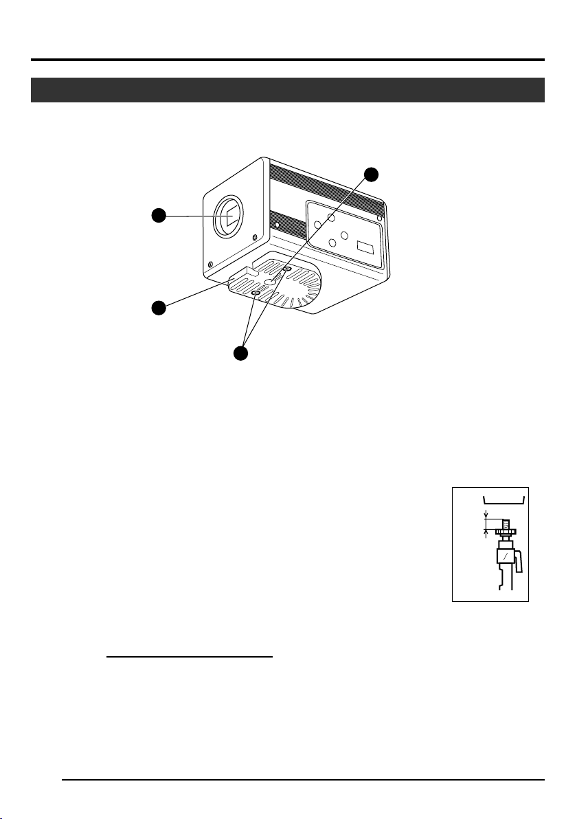
The rating plate (serial number plate) is on the bottom of the unit.
WARNING:
TO REDUCE THE RISK OF FIRE OR
ELECTRIC SHOCK, DO NOT EXPOSE THIS
APPLIANCE TO RAIN OR MOISTURE.
This unit should be used with 12 V DC only.
CAUTION:
To prevent electric shocks and fire hazards, DO
NOT use any other power source.
THIS DEVICE COMPLIES WITH PART 15 OF THE FCC
RULES. OPERATION IS SUBJECT TO THE FOLLOW-
ING TWO CONDITIONS: (1) THIS DEVICE MAY NOT
CAUSE HARMFUL INTERFERENCE, AND (2) THIS
DEVICE MUST ACCEPT ANY INTERFERENCE
RECEIVED, INCLUDING INTERFERENCE THAT MAY
CAUSE UNDESIRED OPERATION.
AVERTISSEMENT:
POUR EVITER LES RISQUES D’INCENDIE
OU D’ELECTROCUTION, NE PAS EXPO-
SER L’APPAREIL A L’HUMIDITE OU A LA
PLUIE.
Cet appareil ne doit être utilisé sur 12 V en
courant continu.
ATTENTION:
Afin d’éviter tout resque d’incendie ou
d’électrocution, ne pas utiliser d’autres sources
d’alimentation électrique.
REMARQUE:
La plaque d’identification (numéro de série) se
trouve sur la partie inférieure de l’appareil.
Cet appareil numérique de la Class B est
conforme à la norme NMB-003 du Canada.
This Class B digital apparatus complies with
Canadian ICES-003.
INFORMATION (F0R CANADA)
RENSEIGNEMENT (POUR CANADA)
SAFETY PRECAUTIONS
3

4
Contents
1. Getting Started
Features ............................................................................................................................................... 6
Points to Note During Use .................................................................................................................... 7
Part Names and Functions ................................................................................................................... 8
Description of Terminals ..................................................................................................................... 12
2. Preparation Before Shooting
Connecting Through Digital Output .................................................................................................... 14
Connecting Through Analog Output ................................................................................................... 16
Mounting the Lens .............................................................................................................................. 17
Connecting the Power Supply ............................................................................................................ 18
Mounting the Camera ......................................................................................................................... 19
Precautions to Prevent Camera From Falling .................................................................................... 20
3. Setting and Adjustment During Shooting
External Monitor Adjustment .............................................................................................................. 21
White Balance Adjustment ................................................................................................................. 22
White Shading Adjustment ................................................................................................................. 24
4. Various Modes of Shooting
Shooting the Computer Monitor .......................................................................................................... 26
Output of Negative Image ................................................................................................................... 27
White Spot Correction ........................................................................................................................ 28

5
5. Setting Via the Menu Screen
Flow of Menu Screens ........................................................................................................................ 30
Setting Procedures ............................................................................................................................. 32
“EXPOSURE” Screen ......................................................................................................................... 33
“ADVANCED EXPOSURE” Screen .................................................................................................... 35
“WHITE BALANCE” Screen................................................................................................................ 36
“PROCESS (1/2)” Screen ................................................................................................................... 38
“PROCESS (2/2)” Screen ................................................................................................................... 40
“SYSTEM” Screen .............................................................................................................................. 41
“MATRIX ADJUST” Screen ................................................................................................................ 42
“CAPTURE” Screen ............................................................................................................................ 43
“FILE MANAGE” Screen ..................................................................................................................... 44
6. Others
Connecting the Remote Control Unit .................................................................................................. 46
Connecting the IEEE 1394 Cable ....................................................................................................... 48
Connecting the analog output (D-SUB) Cable .................................................................................... 48
Technical Information ......................................................................................................................... 49
Specifications ..................................................................................................................................... 50
Notations and Symbols Used in This Manual
Caution
Note
☞
Precautions during operation are stated.
Restrictions of functions and specifications are stated for reference purposes.
Indicates the page and item to refer to.
All product names in this manual are trademarks or registered trademarks of their respective companies.
Marks such as ™, ® and © are not used in this manual.

6
Features
1. Getting Started
●High quality images can be obtained through high sensitivity of 2000 lx (F11) and high resolution of
horizontal resolution at 800 lines via the newly developed 12-bit DSP.
●Miniature and Lightweight Camera that Employs C Mount
Employment of C mount and 1/3-inch color separation optics, and compact design through high-density
mounting of the newly developed IC.
●Equipped with D-SUB terminal
Multiple types of output signals which include RGB, Y/C, composite video and composite sync signal
enable this unit to be connected directly to various types of device.
●Equipped with DV Terminal
Digital video signals can be sent to IEEE 1394 compliant devices.
●SMPTE-compliant Built-in Color Bars Generator
Color monitor can be adjusted with ease with the use of SMPTE color bars.
●Variable Scan Shutter
Eliminates flicker when shooting screen pictures other than NTSC, such as computer screens.
●Slow shutter
Accumulate up to 240 frames of image (approximately 8 seconds). Boosts the brightness of images dur-
ing shooting for objects with insufficient illumination and little motion.
●Equipped with White Shading Function
Corrects color shading triggered by optical characteristics.
●Black Stretch/Black Compress Feature
Stretches or compresses the gain of the dark section in an image to adjust the tone of that section.
●Negative
Used for special purposes such as shooting using films.
●AE (Automatic Exposure)
6 selectable modes in the AE area that are useful when there is a difference in brightness between the
object and its surroundings. In addition, exposure settings can also be performed according to shooting
conditions via selection of AE level adjustment or photometry detection.
●Random Trigger Correction Feature
Fast moving objects can be shot with triggering input timing.
●Freeze Correction Feature
Still images (frozen images) of the camera can be captured with triggering input timing.
●Built-in White Spot Correction Feature
●Equipped with Remote Terminal
Supports remote control via the remote control unit (sold separately).

7
Points to Note During Use
●For important shootings, perform trials in advance to ensure that they are properly recorded.
●We will not compensate for contents lost due to the malfunction of this unit.
䡵Characteristic CCD Phenomena
●Smear and Blooming
When shooting a bright light source, the CCD may induce white streaks (smear) in the vertical direction
of the light source. When the light source is extremely bright, light of the surroundings may expand
(blooming).
●Aliasing
Note that a jagged effect may occur when shooting striped patterns or lines.
●White spot
Operating this unit under a high temperature may give rise to white spots in the image. Ensure to use
this unit within the specified range (–5˚C to 40˚C). White spots may also appear when set to slow
shutter.
This unit comes with the white spot correction feature that helps to reduce this phenomenon.
☞Page 28
䡵Precautions During Handling
●Strong Electromagnetic Waves or Magnetism
When placed near radios or TV transmitters, or transformers and monitors that emit strong magnetism,
noise or color change may occur in the image. Ensure that this unit is kept away from the above
during use.
●Compatible Lens ☞Page 17 ‘Mounting the Lens’
Lens mount of this unit makes use of C mount and there are restrictions on the type of lens to be used.
Pay attention to their performance, dimensions, length of the screw portion when lenses other than
those specified are used.
This unit is not equipped with back focus adjustment function. If zoom len is to be used, please use
only lens which are equipped with back focus function.
●Cleaning the Body of this Unit (Turn off the power before cleaning.)
Wipe using a soft cloth.
Do not wipe with thinner or benzene. These may corrode or tarnish the surface.
When it is extremely dirty, wipe using a neutral detergent diluted with water, follow by wiping with a
dry cloth.
●When not in use, turn off the power of the system to reduce power consumption.
●Do not mount unit at locations that emit radiation, X-rays or corrosive gases.

8
4
1
2
3
1Lens Mount
For mounting lens. Suitable for C mount lens
meant for 3 CCDs.
☞Page 17 ‘Mounting the Lens’
2Camera Mounting Bracket
Supplied together with this unit. Mount it to the
top or bottom surface according to the condi-
tions of use. Mount with the fastening screws
for the camera mounting bracket 3.
☞Page 19 ‘Mounting the Camera’
3Fastening Screws for Camera
Mounting Bracket
Supplied together with this unit.
(M2.6 x 6 mm, 2 pcs)
Caution
Make sure to use screws that are supplied with
this unit. Use of screws that are 6 mm or longer
in length may give rise to malfunction of the unit.
4Camera Mounting Screw Holes (1/
4-20UNC)
Use when mounting this unit to fixer or swivel
bases.
(Use screws that are 7 mm or shorter in length. )
1. Getting Started (continued)
Part Names and Functions
7mm
and
below
Front / Bottom

9
5/ BARS
∞/ AW
SETMENU
1234
5 7 6
8
5[MENU] Menu Button
Press this button for 1-2 seconds. Menu screen
will be output from the various output terminals.
Press the button for 1-2 seconds again to clear
the menu screen.
☞Page 32 ‘Setting Procedures’
6[SET] Set Button
When the menu screen is displayed, use it to
select a submenu or to confirm a selected item
or set value.
☞Page 32 ‘Setting Procedures’
7[5/BARS] Up/Color Bars Button
8[∞/AW] Down/Auto White button
䡵When menu screen is displayed
Press these buttons to move between selection
items on the menu screen.
Use the [5] button to move upwards.
Use the [∞] button to move downwards.
Used for altering the set values when an item
is being selected.
䡵When the menu screen is off
●Press the [AW] button to adjust the white
balance.
☞Page 22 ‘White Balance Adjustment’
●Press the [AW] button for 1-2 seconds to
adjust the white shading.
☞Page 24 ‘White Shading Adjustment’
●Press the [BARS] button to switch between
the color bars output and camera image
output.
Use this button when adjusting the monitor
or when recording color bars signal.
☞Page 21 ‘External Monitor Adjustment’
Part Names and Functions (continued)
Side

10
5/ BARS
∞/ AW
SETMENU
1234
9
ON
OFF
1234
9Function Setting Switch
Use for setting the functions of this unit.
Select the switches when the unit is at power
off condition.
●Switch 1 <DV OUTPUT>
[ON] : Compressed DV signal (IEEE1394)
of the camera images will be out-
put.
[OFF] : DV signal will not be output.
Note
If [ON] is selected, the analog output will
exhibit the same level of horizontal resolution
(about 540 lines) as the DV output.
●Switch 2 <DSUB OUTPUT>
[ON] : Y/C signal will be output.
[OFF] : RGB signal will be output.
Up:
Down:
●Switch 3 <SYNC ON GREEN>
[ON] : Sync signal will be superimposed
onto the Green (G) channel of the
video signal output to the [RGB, Y/
C, SYNC OUT] terminal
0
.
[OFF] : Sync signal will not be superim-
posed.
●Switch 4 <CONTROL MODE>
[ON] : Operate the camera via [DV] termi-
nal (IEEE1394).
Operation via [MENU], [SET], [5/
BARS], [∞/AW] buttons and the re-
mote control unit will not function.
[OFF] : Operate the camera via the buttons
on this unit or the remote control
unit. Operation via [DV] terminal
(IEEE1394) is not functional.
Part Names and Functions (continued)
1. Getting Started (continued)

11
LENS
DV
VIDEO OUT
TRGGER
REMORT
POWER
RGB
,
Y/C
,
SYNC
OUT
DC IN
SEE INSTRUCTION MANUAL
10
12
11
13
141516
17
0
[RGB, Y/C, SYNC OUT] Analog
Output Terminal
Output terminal for R/G/B, Y/C and composite
video/sync signal.
☞Page 10 ‘9Function Setting Switch’
☞Page 13 ‘Description of Terminals’
☞Page 48 ‘Connecting the analog output (D-
SUB) Cable’
![VIDEO OUT] Video Signal Output
Terminal
Output terminal for composite video signals.
Connect to video input terminals such as moni-
tors or switchers.
@[DV] Digital Output Terminal
Digital output terminal for video. Connect this
terminal to computer’s [IEEE 1394] terminal or
[DV] terminal equipped video devices.
●If this terminal is to be used, set Switch 1 lo-
cated at the side of this unit to [ON].
●If this terminal is to be used to operate the
camera, set Switch 4 located at the side of
this unit to [ON].
☞Page 10 ‘9Function Setting Switch’
☞Page 13 ‘Description of Terminals’
☞Page 48 ‘Connecting the IEEE 1394 Cable’
Part Names and Functions (continued)
#[POWER] Power Indicator Light
Lights up when power is supplied to this unit.
$[DC IN] Power Input Terminal
(Mini DIN 8 Pin, Female)
Power of this unit (DC 12 V) is supplied through
this terminal.
Use an AC adaptor (AA-P700) for the power sup-
ply.
☞Page 12 ‘Description of Terminals’
☞Page 18 ‘Connecting the Power Supply’
%[REMOTE] Remote Terminal
(Mini DIN 6 Pin, Female)
Terminal for connection to remote control unit
(RM-LP55 or RM-LP57, both sold separately).
☞Page 12 ‘Description of Terminals’
☞Page 46 ‘Connecting the Remote Control Unit’
Caution
When using this unit as medical equipment, the
remote control unit (RM-LP55 or RM-LP57 sold
separately) cannot be used.
^[TRIGGER] Trigger Terminal
(Mini DIN 5 Pin, Female)
For inputting and outputting the various types of
timing signal when Slow Shutter or Random Trig-
ger function is used.
☞Page 12 ‘Description of Terminals’
☞Page 49 ‘Technical Information’
&[LENS] Lens Connection Terminal
(Mini DIN 8 Pin, Female)
Connect the lens cable.
☞Page 12 ‘Description of Terminals’
☞Page 17 ‘Mounting the Lens’
Back

12
1
4
3
6
7
8
5
2
1
3
5
6
4
2
1
4
3
6
7
8
5
2
1
4
2
5
3
1. Getting Started (continued)
Description of Terminals
Power Input Terminal (Mini DIN 8 Pin,
Female)
Pin No.
1
2
3
4
5
6
7
8
Remote Terminal (Mini DIN 6 Pin, Female)
Lens Connection Terminal (Mini DIN 8
Pin, Female)
Trigger Terminal (Mini DIN 5 Pin, Female)
(TCS7858 : Hoshiden)
Notes
●Please consult your JVC-authorized dealer on
connection of trigger terminal.
●Ensure to use cables that are shielded.
Suitable Plug: Mini DIN 5 PIN
Signal
NC
GND
NC
NC
GND
+ 12 V Input
NC
+ 12 V Input
Pin No.
1
2
3
4
5
6
Signal
GND
OPERATE(L:ON)
GND
SID2(TX)
SID1(RX)
+ 9 V Output
Pin No.
1
2
3
4
5
6
7
8
Signal
LENS TYPE
GND
IRIS CONTROL
+ 12 V Output
SERVO SEL
ZOOM CONTROL
FOCUS CONTROL
Y SIGNAL OUT
Pin No.
1
2
3
4
5
Signal
SI Output
TRIG Input
GND
WEN Output
NC

13
2
4
6
1
3
5
1
5
6
9
Description of Terminals (continued)
Analog Output Terminal (D-sub 9 PIN,
Female)
Digital Output Terminal
Notes
●Cannot be connected to computer monitor.
●Use the function setting switches located at the
side of this unit to select between RGB or Y/C
output.
Note
Ensure to attach the supplied clamp filters to the cables connected to the Analog Signal Output [RGB, Y/C,
SYNC OUT] terminal and Digital Output [DV] terminal in order to reduce unwanted electromagnetic emissions.
☞Page 48
Pin No.
1
2
3
4
5
6
7
8
9
RGB Output
GND
GND
R OUT
G OUT
B OUT
Composite video OUT
Composite sync OUT
GND
GND
Pin No.
1
2
3
4
5
6
7
8
9
Y/C Output
GND
GND
-
Y OUT
C OUT
Composite video OUT
Composite Sync OUT
GND
GND
Pin No.
1
2
3
4
5
6
Signal
VP (POWER)
VG (GND)
TPB -
TPB +
TPA -
TPA +

14
ON
OFF
1234
AC ADAPTER AA-P700
ON
OFF
POWER
5/ BARS
5/ AW
SETMENU
1234
LENS
DV
VIDEO OUT
TRGGER
REMORT
POWER
RGB
,
Y/C
,
SYNC
OUT
DC IN
SEE INSTRUCTION MANUAL
Computer can be used to control this unit remotely, record captured images on digital device or display them
on the computer or monitor. (Please pre-install the exclusive software for this unit.)
Caution
●Perform this when the devices are off.
●When the software has been launched, do not switch on/off the power of the AC adapter or insert and
remove the IEEE 1394 cable.
●Disable the automatic standby or hibernation function of your computer before using it.
●This unit’s power can be supplied from the IEEE 1394 cable. However, use the power supply voltage
between 10.5 V - 15 V if power lens is to be used. Ensure that the supply capacity of the supply source is
adequate in meeting the total power consumptions of both this unit and the power lens used.
1.
Connect the [DV] terminal of this unit to the computer’s DV [IEEE1394] terminal.
2.
Set the Switch 1 and Switch 4 located at the side of this unit to [ON] (upper side).
3.
Switch on the power of this unit.
4.
Set the “DV SYSTEM” under “SYSTEM” screen to “JVC”.
5.
Power on the computer and launch the software.
With the exclusive software provided, it is possible to select the various camera settings and operate the
camera for shooting. For details, please consult your JVC-authorized dealer.
Please refer to the software’s HELP menu for details on how it could be used.
2. Preparation Before Shooting
Connecting Through Digital Output
Notes
●2 or more of this unit cannot be con-
nected to 1 computer.
●Ensure to attach the supplied clamp
filter to the cable connected to the Digi-
tal Output [DV] terminal in order to re-
duce unwanted electromagnetic emis-
sions.
Switch 1 Switch 4
AC IN
Computer ‘Mounting the Lens’
(Page 17)
Clamp filter
(accessories)
Monitor
‘Connecting the
Power Supply’
(Page 18)
AC Adapter
IEEE 1394
Terminal
BNC CABLE
BR-DV3000
BR-DV6000
DV VTR
[VIDEO OUT]
[DV] [DC IN]
[LENS]
AA-P700
Exclusive Software
‘Connecting the
IEEE 1394 Cable’
(Page 48)

15
Connecting Through Digital Output (continued)
䡵Specification of Compatible Computer
●Pentium 4 2.4 GHz or higher DOS/V, PC/AT compatible machine is recommended.
●More than 256 MB RAM is recommended.
●Hard disk with a minimum 20 MB of available space.
●When video recording is performed, 7200 rpm and above IDE disk (RAID system is recommended).
●OS : Windows 2000Pro/XP
●Video card : AGP graphic card incorporated with NVIDIA GeForce4MX or GeForceFX chip (GeForce
4MX420, GeForce FX5700)
●DirectX 9.0 or later versions of Enduser Runtime
䡵Suitable IEEE Host Adapter
●IEEE1394 host adapter card : Matrox Meteor 2-1394, Ratoc REX-CFW3
䡵Compatible Lens
●Fujinon T14 X 5.5MD
䡵Option
●AC Adapter : AA-P700
(Using the exclusive software with other graphic cards and under PC environment other than above-
mentioned might cause a drop in the display performance of the preview window or error might occur.)
For latest information, please check the following homepage.
http: //www.jvc-victor.co.jp/english/pro/prodv/download/index.html
For details, please consult your JVC-authorized dealer.

16
ON
OFF
1234
2. Preparation Before Shooting (continued)
Connecting Through Analog Output
Caution
●Perform this when the devices are off.
●Use the 1/3-inch, C mount adapter for the micro-
scope adapter.
Notes
●Connect a switch between PIN 2 (TRIG) and PIN
3 (GND) of the [TRIGGER] terminal. If this switch
is set to [ON], a trigger will freeze the input image
to the camera and capturing of images synchro-
nized with the trigger is possible.
●Ensure to attach the supplied clamp filter to the
cable connected to the Analog Signal Output
[RGB, Y/C, SYNC OUT] terminal in order to re-
duce unwanted electromagnetic emissions.
☞Page 48
Images taken by this unit can be output to monitor, color video printer or other devices.
1.
Connect device such as the Color Video Printer
to this unit’s [RGB, Y/C, SYNC OUT] terminal.
2.
Set the switches located at the side of this unit.
●Setting Switch 2
Set this switch to [ON] (upper side) for Y/C
output.
Set this switch to [OFF] (lower side) for RGB
output.
●Setting Switch 3
Set this switch to [ON] (upper side) if sync sig-
nal is to be superimposed onto the Green (G)
channel of the video signal.
☞Page 10 ‘9Function Setting Switch’
Example: During RGB output
3.
Switch on the power of this unit.
Trigger Switch
AC Adapter
[TRIGGER]
[REMOTE]
Switch 3Switch 2
AC ADAPTER AA-P700
AC ADAPTER AA-P700
ON
ON
OFF
OFF
POWER
POWER
POWER
POWER
ALARM
ALARM
SHEET
SHEET
PAPER
PAPER
DATA
DATA
OPEN
OPEN
CP700DSA
CP700DSA
MITSUBISHI
MITSUBISHI
ONLINE
ONLINE
COPY
COPY
& CUT
& CUT
PAPERFEED
PAPERFEED
]
LENS
DV
VIDEO OUT
TRGGER
REMORT
POWER
RGB
,
Y/C
,
SYNC
OUT
DC IN
SEE INSTRUCTION MANUAL
SETMENU
Microscope
Adapter
‘Connecting the
Power Supply’
(Page 18)
Color Video Printer etc.
Monitor
REMOTE
CONTROL
UNIT
RM-LP55
RM-LP57
BNC CABLE
AA-P700
[DC IN]
[VIDEO OUT]
[RGB, Y/C, SYNC OUT]
VC-451-2
R
G/Y
B/C
SYNC
VBS
Clamp filter
(accessories)
AC IN

17
Mounting the Lens
Follow the procedures below when mounting the auto iris lens.
Refer to the ‘instruction manual’ for the lens as well.
Caution
●Perform this when the unit is off. Connecting with
the power on may give rise to malfunction of the
unit.
●When removing the lens mount cap, ensure that
no foreign substances are inside the mount.
●Lenses are not supplied with this unit. Depending
on the lens being used, this unit may be damaged.
As such, ensure to use lens that are 4 mm or be-
low, reference from the lens mount.
1.
Align and press the threaded portion of the lens
mount against the threaded portion of this unit’s
lens mount and turn the mount fastening ring
clockwise slowly until the lens is firmly attached
to this unit.
Note
To change the position of the lens rotation,
1First, loosen the mount fastening ring by rotat-
ing it anti-clockwise by 1/4 turn as viewed from
the lens side.
2Turn the lens gently, adjust the position and
tighten the mount fastening ring again.
2.
Plug the lens cable into the [LENS] terminal at
the back of the unit and ensure that it is locked.
Iris control is carried out from this unit.
䡵
Setting the “IRIS MODE” of the “EXPOSURE”
Screen
☞Page 33
●If auto iris lens is to be used and iris control is to
be automatically carried out, set to “AUTO”.
●If auto iris lens is to be used and iris control is to
be fine-tuned, set to “MANUAL”.
4 mm and below
Threaded
Portion
Camera Head
1.
(Male)
Compatible Zoom Lens
T14 x 5.5MD
Lens
Mount Fastening Ring
Lock
2.

18
DC IN
POWER
VIDEO OUTPUT
TO CAMERAS(Y/C) OUTPUT
DC 12V=OUTPUT
EITHER
OUTPUT
MAX 1.25A
SEE INST-
RUCTION
MANUAL
LENS
DV
VIDEO OUT
TRGGER
REMORT
POWER
RGB
,
Y/C
,
SYNC
OUT
DC IN
SEE INSTRUCTION MANUAL
2. Preparation Before Shooting (continued)
Notes
●Ensure to make use of AA-P700 for the power supply.
When connecting, ensure that power switch of AA-P700 is turned OFF.
Connecting with the power on may give rise to malfunction of the equipment.
●When power is supplied, it takes several seconds before this unit is operable.
When the “SHUTTER” item under “EXPOSURE” screen is set to “SLOW”, it might take even longer time.
●Allow a 10 second interval after switching off the power before turning on again. If the power switch is
turned ON and OFF too soon, malfunctioning such as startup failure may occur.
Connecting the Power Supply
Connect the [DC IN] terminal at the back of this unit to the [TO CAMERA] terminal of the AC adaptor (AA-
P700) using the power cable supplied (2 m).
●Insert plug fully, turn ring and ensure
that it is fastened.
[DC IN]
Terminal
Ring
Connect the end with
white marking to the
AC adaptor.
White Marking
Plug
(accessories)
Power Cable (2 m)
[TO CAMERA] Terminal
AC IN
AA-P700 AC Adapter
AC 120 V
Other manuals for KY-F550
1
Table of contents
Other JVC Camcorder manuals

JVC
JVC GR-D31US User manual

JVC
JVC GY-HM250E User manual

JVC
JVC GY-HM700 User manual

JVC
JVC GR-DVL120U User manual

JVC
JVC GYHD110U - Camcorder - 720p Installation manual

JVC
JVC Everio GZ-HD520 User manual

JVC
JVC GZ-HM1U User manual

JVC
JVC GR-AX970 User manual

JVC
JVC GZ-MG67US Quick start guide

JVC
JVC Everio GZ-EX255 Operating and maintenance manual

JVC
JVC GZ-MS100E Series User manual

JVC
JVC ProHD GY-HD251 User manual

JVC
JVC GZ-MG21U User manual

JVC
JVC GR-FX15 User manual

JVC
JVC Everio GZ-HM320 Operating and maintenance manual

JVC
JVC GZ-MS90EK User manual

JVC
JVC LYT0002-0P1A User manual

JVC
JVC GR-AX910U User manual

JVC
JVC Everio GZ-HM690 User manual

JVC
JVC GR-SX22 User manual