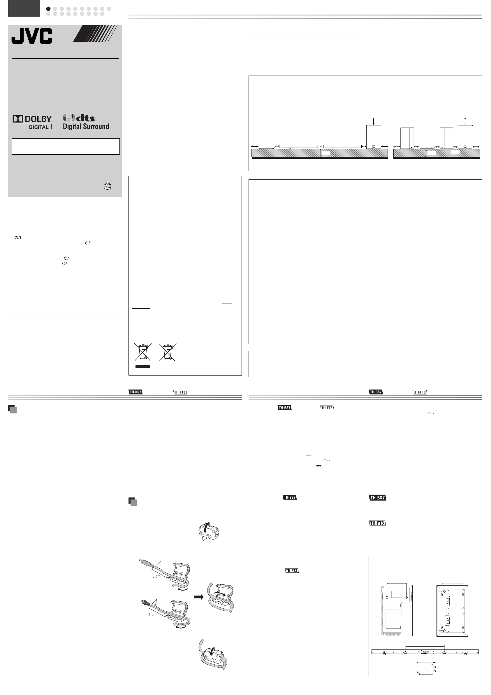
15 cm
15 cm 15 cm
10 cm
AX-THBS7 SP-THBS7F SP-THBS7W
2 cm2 cm
171 mm
8 mm
124 mm
15 cm
15 cm 2 cm 2 cm
2 cm
15 cm
AX-THFT3SP-THFT3F SP-THFT3F SP-THBS7W
10 cm
116 mm
HOME THEATER SOUND SYSTEM
TH-BS7
—Consists of AX-THBS7, SP-THBS7F and
SP-THBS7W
TH-FT3
—Consists of AX-THFT3, SP-THFT3F and
SP-THBS7W
INSTRUCTIONS
Thank you for purchasing a JVC product.
Before operation, please read the instructions carefully.
Warnings, Cautions and Others
Introduction
Notes on handling
Important cautions
Installation of the System
Select a place which is level, dry, and neither too hot nor too cold; between
5°C and 35°C.
Leave sufficient distance between the System and the TV.
Do not use the System in a location near heat sources, or in a place subject to
direct sunlight, excessive dust, or vibration.
Install the System in a location with adequate ventilation to prevent the
internal heat buildup.
The manufacturer accepts absolutely no liability for any accidents or damage
resulting from inadequate assembly or mounting, insufficient strength of
attachment, misuse or abuse, or natural disasters.
Power cord
Do not handle the power cord with wet hands.
A small amount of power is always consumed while the power cord is
connected to the wall outlet.
Do not pull on the cord to unplug the power cord. When unplugging the
power cord, always grasp and pull the plug so as not to damage the cord.
To prevent malfunctions of the System
There are no user-serviceable parts inside. If anything goes wrong, unplug
the power cord and consult your dealer.
Do not insert any metallic objects or liquids into the System.
Do not place anything on top of the System. Doing so may cause the System
to fall, causing malfunctioning and/or injury.
Safety precautions
Avoid moisture, water, and dust
Do not place the System in moist or dusty places.
Avoid high temperatures
Do not expose the System to direct sunlight and do not place it near any
heating devices.
When you are away
When away on holiday or for other reasons for an extended period of time,
disconnect the power cord from the wall outlet.
Do not block the vents
Blocking the vents may damage the System.
Care of the cabinet
Stains on the System should be wiped off with a soft cloth. If the System
is heavily stained, wipe it with a cloth soaked in water diluted neutral
detergent and wrung well, then wipe clean with a dry cloth.
Since the System may deteriorate in quality, become damaged or get its
paint peeled off, be careful about the following:
– DO NOT wipe it forcefully.
– DO NOT wipe it with thinners, benzines or other organic solvents including
disinfectants.
– DO NOT apply any volatile substances such as insecticides to it.
– DO NOT allow any rubber or plastic to remain in contact with it for a long
time.
•
•
•
•
•
•
•
•
•
•
•
•
•
Specifications
Center unit ( AX-THBS7 / AX-THFT3)
Audio section
Output power: 80W (20W × 4) at 4 Ω(THD 10%)
Analog Input: ANALOG IN: 1Vrms/50 k Ω
Digital Input*: OPTICAL DIGITAL IN 1/2/3: –21 dBm to –15 dBm
(660 nm ±30 nm)
General
Power Source (DC IN): DC 19V 3.37 A
AC adaptor (AA-R1902): Input: AC 110 - 240V , 1.5 A - 0.9 A, 50/60 Hz
Output: DC 19V 3.37 A
Dimensions (W × H × D): 186 mm ×31 mm × 300 mm
Mass: 0.73 kg
Corresponding to Linear PCM, Dolby Digital, and DTS (with sampling frequency—
32 kHz, 44.1 kHz, 48 kHz)
Main speaker ( SP-THBS7F)
Type: 1-way Acoustic Suspension Type
(Magnetically-shielded Type)
Speaker unit: 9.5 cm × 1.0 cm Dome × 4
Power Handling Capacity: 20W
Impedance: 4 Ω
Frequency Range: Front speakers: 110 Hz to 40 kHz
Center/Surround speakers: 115 Hz to 40 kHz
Sound Pressure Level: Front speakers: 78 dB/W•m
Center/Surround speakers: 79 dB/W•m
Dimensions (W × H × D): 900 mm × 36.7 mm × 53 mm
Mass: 1.6 kg
Main speakers ( SP-THFT3F)
Type: 1-way Acoustic Suspension Type
(Magnetically-shielded Type)
Speaker unit: 9.5 cm × 1.0 cm Dome × 2 (per each speaker)
Power Handling Capacity: 20W
Impedance: 4 Ω
Frequency Range: 110 Hz to 23 kHz
Sound Pressure Level: 81.5 dB/W•m
Dimensions (W × H × D): 186 mm × 300 mm × 30.8 mm
186 mm × 296 mm × 87 mm (with stand)
Mass: 0.85 kgper each speaker
0.94 kgper each speaker (with stand)
Powered Subwoofer (SP-THBS7W)
Output power 100W, at 3 Ω(THD 10%)
Type: 1-way Bass-ReflexType
Speaker unit: 16 cm cone × 1
Power Handling Capacity: 100W
Impedance: 3 Ω
Frequency Range: 45 Hz to 5 kHz
*
: Only for TH-BS7 / : Only for TH-FT3
If water gets inside the System
Turn the System off and disconnect the power cord from the wall outlet,
then call the store where you purchased this System. Using the System in this
condition may cause a fire or electrical shock.
Cautions when installing the units on the wall
Use screws which are compatible with the strength and material of the pillar
or wall to prevent the units from falling off.
Do not install the center unit and speaker onto a plywood or plasterboard
wall; otherwise, they will fall and sustain damage.
When installing the center unit and speaker on the wall;
– Be sure to have them installed on the wall by qualified personnel.
– Care must be taken when selecting a location for installation on the wall.
Injury to personnel or damage to equipment may result if the installed
unit interfere with daily activities.
– AC adaptor should not be hanging/put above of any other items. It is
acceptable to place the AC adaptor on the flat floor only.
Using the core filter
Attach the provided core filters to the power cord and the external components
cord, then the core filters reduce interference.
1Release the stopper of the core filter.
2Run the cord through the core filter, and wind the cord firmly once
inside the cutout of the core filter as shown in the illustration.
* You can wind 2 external components cords together.
3Close the core filter until it clicks shut.
CAUTION
Do not damage the cord by applying excessive force when winding.
•
•
•
•
Sound Pressure Level: 82 dB/W•m
Power Requirements: AC 230V , 50 Hz
Power Consumption: 30W (during operation)
0.8W (in Standby mode)
Dimensions (W × H × D): 215 mm × 352 mm × 254 mm
Mass: 5 kg
Supplied accessories
If anything is missing, contact your dealer immediately.
Remote control RM-STHFT1A (× 1)
Lithium coin battery CR2025 (× 1)
– The battery has been installed in the remote control when shipped from
the factory.
AC adaptor AA-R1902 (× 1)
AC power cord (× 1)
Core filters (× 2)
Feet
– Flat type (φ7.8 mm) (× 5)
– Slanted type (× 2)
Speaker cords (3m) (× 2)
Stands (× 2)
Screws for stand (M5 × 10 mm) (× 4)
– The screws are packed in the hole on the top of the speaker packing
cushion.
•
•
•
•
•
•
•
•
•
ENGLISH
: Only for TH-BS7 / : Only for TH-FT3
Dimensions of the wall-mount attachment for the center unit and
speakers
Designs & specifications are subject to change without notice.
Power cord
Stopper
External components cords*
IMPORTANT for the U.K.
DO NOT cut off the mains plug from this equipment. If the plug fitted is not
suitable for the power points in your home or the cable is too short to reach
a power point, then obtain an appropriate safety approved extension lead or
consult your dealer.
BE SURE to replace the fuse only with an identical approved type, as originally
fitted.
If nonetheless the mains plug is cut off ensure to remove the fuse and dispose
of the plug immediately, to avoid a possible shock hazard by inadvertent
connection to the mains supply.
If this product is not supplied fitted with a mains plug then follow the
instructions given below:
IMPORTANT:
DO NOT make any connection to the terminal which is marked with the letter E
or by the safety earth symbol or coloured green or green-and-yellow.
The wires in the mains lead on this product are coloured in accordance with the
following code:
Blue: Neutral
Brown: Live
As these colours may not correspond with the coloured markings identifying
the terminals in your plug proceed as follows:
The wire which is coloured blue must be connected to the terminal which is
marked with the letter N or coloured black.
The wire which is coloured brown must be connected to the terminal which is
marked with the letter L or coloured red.
IF IN DOUBT - CONSULT A COMPETENT ELECTRICIAN.
Information for Users on Disposal of Old Equipment and Batteries
[European Union]
These symbols indicate that the electrical and electronic equipment
and the battery with this symbol should not be disposed of as general
household waste at its end-of-life. Instead, the products should be handed
over to the applicable collection points for the recycling of electrical and
electronic equipment as well as batteries for proper treatment, recovery
and recycling in accordance with your national legislation and the
Directive 2002/96/EC and 2006/66/EC.
By disposing of these products correctly, you will help to conserve natural
resources and will help to prevent potential negative effects on the
environment and human health which could otherwise be caused by
inappropriate waste handling of these products.
For more information about collection points and recycling of these
products, please contact your local municipal office, your household waste
disposal service or the shop where you purchased the product.
Penalties may be applicable for incorrect disposal of this waste, in
accordance with national legislation.
[Business users]
If you wish to dispose of this product, please visit our web page http://
www.jvc.eu/ to obtain information about the take-back of the product.
[Other Countries outside the European Union]
These symbols are only valid in the European Union.
If you wish to dispose of these items, please do so in accordance with
applicable national legislation or other rules in your country for the
treatment of old electrical and electronic equipment and batteries.
Products
Notice:
The sign Pb below the symbol for
batteries indicates that this battery
contains lead.
CAUTION
To reduce the risk of electrical shocks, fire, etc.:
Do not remove screws, covers or cabinet.
Do not expose this appliance to rain or moisture.
CAUTION (AX-THBS7/AX-THFT3)
The button in any position does not disconnect the mains line. Disconnect
the mains plug to shut the power off completely (the symbol goes off).
The MAINS plug or an appliance coupler is used as the disconnect device, the
disconnect device shall remain readily operable.
When the System is on standby, the symbol lights red.
When the System is turned on, the symbol goes off.
The power can be remote controlled.
CAUTION (SP-THBS7W)
The power supply to the subwoofer is linked to the center unit. Disconnect the
mains plug to shut the power off completely (the STANDBY/ON lamp goes off).
The MAINS plug or an appliance coupler is used as the disconnect device, the
disconnect device shall remain readily operable.
When the System is on standby, the STANDBY/ON lamp lights red.
When the System is turned on, the STANDBY/ON lamp lights blue.
CAUTION
Do not block the ventilation openings or holes. (If the ventilation openings
or holes are blocked by a newspaper or cloth, etc., the heat may not be able
to get out.)
Do not place any naked flame sources, such as lighted candles, on the
apparatus.
When discarding batteries, environmental problems must be considered and
local rules or laws governing the disposal of these batteries must be followed
strictly.
Do not expose this apparatus to rain, moisture, dripping or splashing and
that no objects filled with liquids, such as vases, shall be placed on the
apparatus.
1.
2.
•
•
•
•
•
•
•
•
SAFETY INSTRUCTIONS
“SOME DOS AND DON’TS ON THE SAFE USE OF EQUIPMENT”
This equipment has been designed and manufactured to meet international safety standards but, like any electrical equipment, care must be taken if you are
to obtain the best results and safety is to be assured.
★★★★★★★★★★★★★★★★★★★★★★★★★★★★★★★★★★★★★★★★★★★★★★
Do read the operating instructions before you attempt to use the equipment.
Do ensure that all electrical connections (including the mains plug, extension leads and interconnections between pieces of equipment) are properly made and
in accordance with the manufacturer’s instructions. Switch off and withdraw the mains plug when making or changing connections.
Do consult your dealer if you are ever in doubt about the installation, operation or safety of your equipment.
Do be careful with glass panels or doors on equipment.
★★★★★★★★★★★★★★★★★★★★★★★★★★★★★★★★★★★★★★★★★★★★★★
DON’T continue to operate the equipment if you are in any doubt about it working normally, or if it is damaged in any way—switch off, withdraw the mains
plug and consult your dealer.
DON’T remove any fixed cover as this may expose dangerous voltages.
DON’T leave equipment switched on when it is unattended unless it is specifically stated that it is designed for unattended operation or has a standby mode.
Switch off using the switch on the equipment and make sure that your family know how to do this.
Special arrangements may need to be made for infirm or handicapped people.
DON’T use equipment such as personal stereos or radios so that you are distracted from the requirements of traffic safety. It is illegal to watch television whilst
driving.
DON’T listen to headphones at high volume as such use can permanently damage your hearing.
DON’T obstruct the ventilation of the equipment, for example with curtains or soft furnishings.
Overheating will cause damage and shorten the life of the equipment.
DON’T use makeshift stands and NEVER fix legs with wood screws—to ensure complete safety always fit the manufacturer’s approved stand or legs with the
fixings provided according to the instructions.
DON’T allow electrical equipment to be exposed to rain or moisture.
ABOVE ALL
– NEVER let anyone, especially children, push anything into holes, slots or any other opening in the case.
—this could result in a fatal electrical shock.
– NEVER guess or take chances with electrical equipment of any kind—it is better to be safe than sorry!
Dear Customer,
This apparatus is in conformance with the valid European directives and
standards regarding electromagnetic compatibility and electrical safety.
European representative of Victor Company of Japan, Limited is:
JVC Technical Services Europe GmbH
Postfach 10 05 04
61145 Friedberg
Germany
Manufactured under license from Dolby Laboratories. Dolby and the double-D symbol are trademarks of Dolby Laboratories.
Manufactured under license under U.S. Patent numbers: 5,451,942; 5,956,674; 5,974,380; 5,978,762; 6,487,535 and other U.S. and worldwide patents
issued and pending. DTS and DTS Digital Surround are registered trademarks and the DTS logos and Symbol are trademarks of DTS, Inc. © 1996-2008 DTS,
Inc. All Rights Reserved.
•
•
Battery
GVT0290-001A[B]
0909WMKMDWJMM
EN
© 2009 Victor Company of Japan, Limited
CAUTION: Proper Ventilation
To avoid risk of electric shock and fire, and to prevent damage, locate the apparatus as follows:
Front: No obstructions and open spacing.
Sides/ Top/ Back: No obstructions should be placed in the areas shown by the dimensions below.
Bottom: Place on the level surface. Maintain an adequate air path for ventilation by placing on a stand with a height of 10 cm or more.
1.
2.
3.
TH-BS7 TH-FT3
AX-THBS7/AX-THFT3
CAUTION
Battery shall not be exposed to excessive heat such as sunshine, fire or the like.
Do not use another AC adaptor to connect this model.
SP-THBS7F
SP-THFT3F
TH-BS7FT3_B_f.indd 1TH-BS7FT3_B_f.indd 1 09.9.9 11:20:23 AM09.9.9 11:20:23 AM


