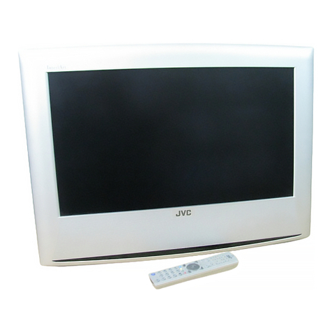
JVC InteriArt LT-23D50BK User manual

SERVICE MANUAL
COPYRIGHT © 2005 Victor Company of Japan, Limited No.YA221
2005/8
WIDE LCD PANEL TELEVISION
YA22120058
LT-23D50BK
TABLE OF CONTENTS
1 PRECAUTION. . . . . . . . . . . . . . . . . . . . . . . . . . . . . . . . . . . . . . . . . . . . . . . . . . . . . . . . . . . . . . . . . . . . . . . . . 1-3
2 SPECIFIC SERVICE INSTRUCTIONS . . . . . . . . . . . . . . . . . . . . . . . . . . . . . . . . . . . . . . . . . . . . . . . . . . . . . . 1-6
3 DISASSEMBLY . . . . . . . . . . . . . . . . . . . . . . . . . . . . . . . . . . . . . . . . . . . . . . . . . . . . . . . . . . . . . . . . . . . . . . . 1-9
4 ADJUSTMENT . . . . . . . . . . . . . . . . . . . . . . . . . . . . . . . . . . . . . . . . . . . . . . . . . . . . . . . . . . . . . . . . . . . . . . . 1-13
5 TROUBLESHOOTING . . . . . . . . . . . . . . . . . . . . . . . . . . . . . . . . . . . . . . . . . . . . . . . . . . . . . . . . . . . . . . . . . 1-13
P
MENU
BACK
PC
TV
VCR DVDTV

1-2 (No.YA221)
SPECIFICATION
Design & specifications are subject to change without notice.
Items Contents
Dimensions ( W ×H ×D ) 61.4cm ×48.2cm ×24.0cm [Included stand]
61.4cm ×43.8cm ×7.9cm [TV only]
Mass 7.4kg [Included stand]
6.4kg [TV only]
Power Input AC100 to AC240 V, 50 Hz
Power Consumption 108W (Standby: 3.0W)
TV RF System Analog
Digital
CCIR (B/G, I, D/K, L)
DVB-T
Colour System PAL, SECAM, NTSC 3.58/4.43 [EXT only]
Stereo System NICAM (B/G, I, D/K, L), A2 (B/G, D/K)
Receiving Frequency Analog
Digital
CATV
VHF: 47 MHz - 470 MHz
UHF: 470 MHz - 862 MHz
UHF: 474 MHz - 858 MHz
68 MHz - 174 MHz, 230 MHz - 470 MHz
Intermediate
Frequency
VIF
SIF
38.9 MHz (B/G, I, D/K, L)
33.4 MHz (5.5 MHz: B/G)
32.9 MHz (6.0 MHz: I)
32.4 MHz (6.5 MHz: D/K, L)
Colour Sub
Carrier Frequency
PAL
SECAM
NTSC
4.43 MHz
4.40625 MHz / 4.25MHz
3.58 MHz / 4.43 MHz
Teletext System Analog
Digital
TOP, FLOF (Fastext level 2.5), WST(World Standard system)
MHEG 5 UK profile
LCD panel 23V-inch wide aspect (16:9)
Screen Size Diagonal : 58.3cm (H:50.8cm ×V : 28.6cm)
Display Pixels Horizontal : 1366 dots ×Vertical : 768 dots (W-XGA)
Audio Power Output 5W + 5W(10% THD)
Speaker 3.4cm ×14.5cm oval type ×2
Aerial terminal (VHF/UHF) EU-type connector, 75Ωunbalanced, coaxial
EXT-1 / EXT-2 (Input / Output) 21-pin Euro connector (SCART socket ) ×2
EXT-3(Input) Component Video
625p / 525p / 625i / 525i
Audio
RCA pin jack ×3
Y : 1V (p-p), Positive (Negative sync provided), 75 Ω
Cb/Cr : 0.7V(p-p), 75 Ω
500mV(rms) (-4dBs), high impedance, RCA pin jack ×2
EXT-4 (Input) S-Video
Video
Audio
Mini-DIN 4 pin ×1
Y: 1V (p-p), Positive (Negative sync provided), 75 Ω
C: 0.286V (p-p) (Burst signal), 75 Ω
1V (p-p), Positive (Negative sync provided), 75 Ω, RCA pin jack ×1
500mV (rms), High impedance, RCA pin jack ×2
PC (RGB) Input D-sub 15pin ×1
R/G/B : 0.7V (p-p), 75Ω
HD / VD : 1V (p-p) to 5V (p-p), high impedance
< Available signal >
Horizontal : 30kHz - 69kHz
Vertical : 50Hz - 75Hz
[Resolution : 640 pixels ×400 pixels, 640 pixels ×480 pixels(VGA), 720 pixels
×400 pixels, 800 pixels ×600 pixels(SVGA), 1024 pixels ×768 pixels(XGA),
1280 pixels ×720 pixels, 1360 pixels ×768 pixels(W-XGA)]
PC AUDIO input 3.5mm stereo mini jack ×1
Audio output 500mV (rms), Low impedance, RCA pin jack ×2
Subwoofer output More than 0 to 1000mV (rms) (+2.2dBs), low impedance (80Hz when modulated
100%), RCA pin jack ×1
Headphone 3.5mm stereo mini jack ×1
Remote Control Unit RM-C1895 (AA/R6 dry cell battery ×2)

(No.YA221)1-3
SECTION 1
PRECAUTION
1.1 SAFETY PRECAUTIONS
(1) The design of this product contains special hardware and many circuits and components specially for safety purposes. For
continued protection, no changes should be made to the original design unless authorized in writing by the manufacturer.
Replacement parts must be identical to those used in the original circuits. Service should be performed by qualified personnel
only.
(2) Alterations of the design or circuitry of the product should not be made. Any design alterations or additions will void the
manufacturer's warranty and will further relieve the manufacturer of responsibility for personal injury or property damage
resulting therefrom.
(3) Many electrical and mechanical parts in the product have special safety-related characteristics. These characteristics are often
not evident from visual inspection nor can the protection afforded by them necessary be obtained by using replacement
components rated for higher voltage, wattage, etc. Replacement parts which have these special safety characteristics are
identified in the Parts List of Service Manual. Electrical components having such features are identified by shading on the
schematics and by ( ) on the Parts List in the Service Manual. The use of a substitute replacement which does not have the
same safety characteristics as the recommended replacement part shown in the Parts List of Service Manual may cause shock,
fire, or other hazards.
(4) The leads in the products are routed and dressed with ties, clamps, tubing’s, barriers and the like to be separated from live parts,
high temperature parts, moving parts and / or sharp edges for the prevention of electric shock and fire hazard. When service is
required, the original lead routing and dress should be observed, and it should be confirmed that they have been returned to
normal, after re-assembling.
WARNING
(1) The equipment has been designed and manufactured to meet international safety standards.
(2) It is the legal responsibility of the repairer to ensure that these safety standards are maintained.
(3) Repairs must be made in accordance with the relevant safety standards.
(4) It is essential that safety critical components are replaced by approved parts.
(5) If mains voltage selector is provided, check setting for local voltage.

1-4 (No.YA221)
1.2 INSTALLATION
1.2.1 HEAT DISSIPATION
If the heat dissipation vent behind this unit is blocked, cooling
efficiency may deteriorate and temperature inside the unit will
rise. The temperature sensor that protects the unit will be
activated when internal temperature exceeds the pre-determined
level and power will be turned off automatically.Therefore,
please make sure pay attention not to block the heat dissipation
vent as well as the ventilation outlet behind the unit and ensure
that there is room for ventilation around it.
1.2.2 INSTALLATION REQUIREMENTS
Ensure that the minimal distance is maintained, as specified
below, between the unit with and the surrounding walls, as well
as the floor etc.Install the unit on stable flooring or stands.Take
precautionary measures to prevent the unit from tipping in order
to protect against accidents and earthquakes.
1.2.3 INSTALLATION REQUIREMENTS
To ensure safety in an emergency such as an earthquake, and
to prevent accidents, ensure that measures are taken to prevent
the TV dropping or falling over.
Use the supplied screws to firmly attach the supplied hooks
(OPTION) to the back of the TV, and use commercially available
cord to fix the TV to rigid components such as walls and columns.
1.2.4 NOTES ON HANDLING
(1) WHEN TAKING UNIT OUT OF A PACKING CASE
When taking the unit out of a packing case, do not grasp
the upper part of the unit. If you take the unit out while
grasping the upper part, the LCD PANEL may be damaged
because of a pressure. Instead of grasping the upper part,
put your hands on the lower backside or sides of the unit.
(2) AS FOR PRESSING OR TOUCHING A SPEAKER
Be careful not to press the opening of the speaker in the
lower part of the unit and around them since the decorative
sheet on the surface of the openings may be deformed.
*Diagram differs from actual appearance.
Ventilation hole
*Diagram differs from actual appearance.
100 mm
100 mm
100 mm
100 mm
50 mm
TV
/
AV
MENU
P/ch
Hook
Wall
It fixes in a band.
TV Stand
*Diagram differs from actual appearance.

(No.YA221)1-5
1.3 HANDLING LCD PANEL
1.3.1 PRECAUTIONS FOR TRANSPORTATION
When transporting the unit, pressure exerted on the internal LCD
panel due to improper handling (such as tossing and dropping)
may cause damages even when the unit is carefully packed. To
prevent accidents from occurring during transportation, pay
careful attention before delivery, such as through explaining the
handling instructions to transporters.
Ensure that the following requirements are met during
transportation, as the LCD panel of this unit is made of glass and
therefore fragile:
(1) USE A SPECIAL PACKING CASE FOR THE LCD PANEL
When transporting the LCD panel of the unit, use a special
packing case (packing materials). A special packing case
is used when a LCD panel is supplied as a service spare
part.
(2) ATTACH PROTECTION SHEET TO THE FRONT
Since the front (display part) of the panel is vulnerable,
attach the protection sheet to the front of the LCD panel
before transportation. Protection sheet is used when a LCD
panel is supplied as a service spare part.
(3) AVOID VIBRATIONS AND IMPACTS
The unit may be broken if it is toppled sideways even when
properly packed. Continuous vibration may shift the gap of
the panel, and the unit may not be able to display images
properly. Ensure that the unit is carried by at least 2
persons and pay careful attention not to exert any vibration
or impact on it.
(4) DO NOT PLACE EQUIPMENT HORIZONTALLY
Ensure that it is placed upright and not horizontally during
transportation and storage as the LCD panel is very
vulnerable to lateral impacts and may break. During
transportation, ensure that the unit is loaded along the
traveling direction of the vehicle, and avoid stacking them
on one another. For storage, ensure that they are stacked
in 2 layers or less even when placed upright.
1.3.2 OPTICAL FILTER (ON THE FRONT OF THE LCD PANEL)
(1) Avoid placing the unit under direct sunlight over a
prolonged period of time. This may cause the optical filter
to deteriorate in quality and COLOUR.
(2) Clean the filter surface by wiping it softly and lightly with a
soft and lightly fuzz cloth (such as outing flannel).
(3) Do not use solvents such as benzene or thinner to wipe the
filter surface. This may cause the filter to deteriorate in
quality or the coating on the surface to come off. When
cleaning the filter, usually use the neutral detergent diluted
with water. When cleaning the dirty filter, use water-diluted
ethanol.
(4) Since the filter surface is fragile, do not scratch or hit it with
hard materials. Be careful enough not to touch the front
surface, especially when taking the unit out of the packing
case or during transportation.
1.3.3 PRECAUTIONS FOR REPLACEMENT OF EXTERIOR
PARTS
Take note of the following when replacing exterior parts (REAR
COVER, FRONT PANEL, etc.):
(1) Do not exert pressure on the front of the LCD panel (filter
surface). It may cause irregular COLOUR.
(2) Pay careful attention not to scratch or stain the front of the
LCD panel (filter surface) with hands.
(3) When replacing exterior parts, the front (LCD panel) should
be placed facing downward. Place a mat, etc. underneath
to avoid causing scratches to the front (filter surface).
1-6 (No.YA221)
SECTION 2
SPECIFIC SERVICE INSTRUCTIONS
2.1 FEATURES
DVB-T (DIGITAL TERRESTRIAL BROADCASTING)
This TV can receive both Digital terrestrial broadcasting (DVB-
T) and Analogue terrestrial broadcasting.
T-V LINK
When you have a T-V LINK compatible VCR connected to the
EXT-2 Terminal on the TV,it is easier to set up the VCR and to
view videos.
ZOOM
This function can change the screen size according to the
picture aspect ratio.
OFF TIMER
This function can set the TV to automatically turn off after a set
time.
COLOUR SYSTEM
If the picture is not clear or no colour appears, change the
current colour system to another colour system.
2.2 21-PIN EURO CONNECTOR (SCART) : EXT-1 / EXT-2
(P-P= Peak to Peak, B-W= Blanking to white peak)
Pin No. Signal designation Matching value EXT-1 EXT-2
1 AUDIO R output 500mV(rms) (Nominal),, Low impedance Used (TV OUT) Used (LINE OUT)
2 AUDIO R input 500mV(rms) (Nominal),, High impedance Used (R1) Used (R2)
3 AUDIO L output 500mV(rms) (Nominal),, Low impedance Used (TV OUT) Used (LINE OUT)
4 AUDIO GND Used Used
5 GND (B) Used Used
6 AUDIO L input 500mV(rms) (Nominal),, High impedance Used (L1) Used (L2)
7 B input 700mV(B-W), 75ΩUsed Used
8 FUNCTION SW
(SLOW SW)
Low : 0V-3V
High : 8V-12V, High impedance
Used Used
9 GND (G) Used Used
10 SCL / T-V LINK Not used Used
(SCL2 / TV-LINK)
11 G input 700mV(B-W), 75ΩUsed Used
12 SDA Not used Used (SDA2)
13 GND (R) Used Used
14 GND (YS) Used Not used
15 R / C input R : 700mV(B-W), 75Ω
C : 300mV(P-P), 75ΩUsed (R) Used (C2/R)
16 Ys input (FAST SW) Low : 0V-0.4V, High : 1V-3V, 75ΩUsed Used
17 GND (VIDEO output) Used Used
18 GND (VIDEO input) Used Used
19 VIDEO output 1V(P-P) (Negative sync), 75ΩUsed (TV OUT) Used (LINE OUT)
20 VIDEO / Y input 1V(P-P) (Negative sync), 75ΩUsed Used
21 COMMON GND Used Used
20 18 16 14 12 10 8 6 4 2
21 19 17 15 13 11 9 7 5 3 1
[Pin assignment]

(No.YA221)1-7
2.3 TECHNICAL INFORMATION
2.3.1 LCD PANEL
This unit uses the flat type panel LCD (Liquid Crystal Display) panel that occupies as little space as possible, instead of the
conventional CRT (Cathode Ray Tube), as a display unit.
Since the unit has the two polarizing filter that are at right angles to each other, the unit adopts "normally black" mode, where light
does not pass through the polarizing filter and the screen is black when no voltage is applied to the liquid crystals.
2.3.1.1 SPECIFICATIONS
The following table shows the specifications of this unit.
2.3.1.2 PIXEL FAULT
There are three pixel faults - bright fault , dark fault and flicker fault - that are respectively defined as follows.
BRIGHT FAULT
In this pixel fault, a cell that should not light originally is lighting on and off.
For checking this pixel fault, input ALL BLACK SCREEN and find out the cell that is lighting on and off.
DARK FAULT
In this pixel fault, a cell that should light originally is not lighting or lighting with the brightness twice as brighter as originally lighting.
For checking this pixel fault, input 100% of each R/G/B colour and find out the cell that is not lighting.
FLICKER FAULT
In the pixel fault, a cell that should light originally or not light originally is flashing on and off.
For checking this pixel fault, input ALL BLACK SCREEN signal or 100% of each RGB colour and find out the cell that is flashing on
and off.
Item Specifications Remarks
Displayed colour 16777216 colours 256 colours for R, G, and B
Brightness 450cd/m2
Contrast ratio 800: 1
Response time 25ms
View angle Horizontally: 170°, Vertically: 170°

1-8 (No.YA221)
2.4 BASIC OPERATION OF SERVICE MODE
2.4.1 HOW TO ENTER THE SERVICE MODE
(1) Press [INFORMATION] key and [MUTING] key on the
remote control unit simultaneously to enter the SERVICE
MODE SCREEN.
2.4.2 HOW TO EXIT THE SERVICE MODE
Press the [MENU] key to exit the Service mode.
2.4.3 CHANGE AND MEMORY OF SETTING VALUE
SELECTION OF SETTING MENU & ITEM
•[FUNCTION /]key : Select the SETTING MENU & ITEM
•[OK] key : Decision the SETTING MENU & ITEM
CHANGE OF SETTING VALUE (DATA)
• [FUNCTION /] key.
MEMORY OF SETTING VALUE (DATA)
The setting value will be stored automatically when release the
REMOTE CONTROL UNIT keys
2.4.4 SERVICE MODE SELECT KEY LOCATION
2.4.5 SERVICE MODE SETTING ITEMS
Service
Adjust ...
Options...
Aps Wss Test ...
17JVC 0. 0. 86
Sep 27 2004 08:47:10
SERVICE MODE SCREEN
[OK]
[[
]]
Setting
menu Setting items Contents
Adjust Group ----
Mode ----
Col. Temp. ----
Contrast ----
Brightness ----
Colour ----
Sharpness ----
Red ----
Green ----
Blue ----
Aps Volume ----
Option 1 First APS If ON, TV starts with APS
menu at Start-up
FM Prs Avl On Adjusts the FM Prescaler
value, when Automatic
Volume Levelling is On
Nicam Prs Avl On Adjusts the Nicam Prescal-
er value, when Automatic
Volume Levelling is On
Scart Prs Avl On Adjusts the Scart Volume
value, when Automatic
Volume Levelling is On
Scart Volume Avl On Adjusts the Scart Volume
value, when Automatic
Volume Levelling is On
FM Prs Avl Off Adjusts the FM Prescaler
value, when Automatic
Volume Levelling is Off
Option 2 Nicam Prs Avl Off Adjusts the Nicam Prescal-
er value, when Automatic
Volume Levelling is Off
Scart Prs Avl Off Adjusts the Scart Prescal-
er value, when Automatic
Volume Levelling is Off
Scart Volume Avl Off Adjusts the Scart Volume
value, when Automatic
Volume Levelling is On
Avl Enable/disable Automatic
Volume Levelling System
Sound ----
Carrier ----
LDLY ----
AGC ----
Aps Wss Test Programme ----
VPS ----
Scart Volume Avl Off ----
Pdc Format 1 ----
Pdc Format 2 ----
Name ----
WSS ----

(No.YA221)1-9
SECTION 3
DISASSEMBLY
3.1 DISASSEMBLY PROCEDURE
NOTE:
• Make sure that the power cord is disconnected from the outlet.
• Pay special attention not to break or damage the parts.
• When removing each board, remove the connectors as required.
• Taking notes of the connecting points (connector numbers) makes service procedure manageable.
• Make sure that there is no bent or stain on the connectors before inserting, and firmly insert the connectors.
3.1.1 REMOVING THE STAND UNIT
• Remove the TFT DOOR SOCKET, AV DOOR SOCKET & CI
COVER.
(1) Remove the 2 screws [A], then remove the FOOT TOP
COVER.
(2) Remove the 4 screws [B], then remove the STAND UNIT.
3.1.2 REMOVING THE HANDLE
• Remove the STAND UNIT.
(1) Remove the 4 screws [C], then remove the HANDLE.
3.1.3 REMOVING THE BACK COVER
• Remove the STAND UNIT.
• Remove the HANDLE.
(1) Remove the 5 screws [D], then remove the BACK COVER
toward you.
3.1.4 REMOVING THE BRACKET CI
• Remove the STAND UNIT.
• Remove the HANDLE.
• Remove the BACK COVER.
(1) Remove the 4 screws [E], then remove the MMC CARD.
(2) Remove the 2 screws [F], then remove the BRACKET CI.
3.1.5 REMOVING THE FAV PWB
• Remove the STAND UNIT.
• Remove the HANDLE.
• Remove the BACK COVER.
(1) Remove the 2 screws [G], then remove the FAV PWB.
3.1.6 REMOVING THE BRACKET SCART
• Remove the STAND UNIT.
• Remove the HANDLE.
• Remove the BACK COVER.
(1) Remove the 2 screws [H], then remove the BRACKET
SCART.
3.1.7 REMOVING THE MAIN PWB
• Remove the STAND UNIT.
• Remove the HANDLE.
• Remove the BACK COVER.
• Remove the BRACKET SCART.
(1) Remove the 9 screws [J], then remove the MAIN PWB.
3.1.8 REMOVING THE LCD PANEL UNIT
• Remove the STAND UNIT, HANDLE & BACK COVER.
• Remove the BRACKET SCART & MAIN PWB.
(1) Remove the 1 screw [K], then remove the DISPLAY
SUPPORT from the FRONT COVER.
(2) Follow the same step when removing the other three
DISPLAY SUPPORTS.
(3) Remove the 2 screws [L], then remove the MAIN FRAME
with the LCD PANEL UNIT from the FRONT COVER.
(4) Remove the 7 screws [M], then remove the LCD PANEL
UNIT from the MAIN FRAME.
NOTE:
• Pay special attention not to break or damage on the LCD
PANEL face or frame.
• The LCD PANEL UNIT is fixed to the FRONT COVER (at the
back side) by using double-side adhesive tapes. To remove
the LCD PANEL UNIT, remove the adhesive tape on the
FRONT PANELslowly.
3.1.9 REMOVING THE SIDE CONTROL PWB
• Remove the STAND UNIT, HANDLE & BACK COVER.
(1) Remove the 2 screws [N], then remove the SIDE
CONTROL PWB with the control knob.
(2) Remove the SIDE CONTROL PWB from the control knob.
3.1.10 REMOVING THE LED PWB
• Remove the STAND UNIT, HANDLE & BACK COVER.
(1) Remove the 1 screw [P], then remove the LED PWB from
the FRONT COVER.
3.1.11 REMOVING THE HEADPHONE PWB
• Remove the STAND UNIT, HANDLE & BACK COVER.
(1) Remove the 1 screw [Q], then remove the HEADPHONE
PWB from the FRONT COVER.
3.1.12 REMOVING THE SPEAKERS
• Remove the STAND UNIT, HANDLE & BACK COVER.
(1) Remove the 2 screws [R] from each speaker.
(2) Remove the SPEAKER from the FRONT COVER.
(3) Follow the same when removing the other hand speaker.

1-10 (No.YA221)
Fig.1
G
E
F
R
D
C
A
B
Q
P
N
K
M
J
H
L
STAND UNIT
SPEAKER
(x2)
HEADPHONE
PWB
FRONT COVER
LED PWB
LENS LED
LENS IR
SIDE CONTROL
PWB
BUTTON
FUNCTION
PLATE
BUTTON FUNCTION
LCD PANEL UNIT
DISPLAY SUPPORT
MAIN FRAME
MAIN PWB
BRACKET SCART
TUNER
FAV PWB
BACK COVER
TFT DOOR
SOCKET
FOOT TOP
COVER
AV DOOR
SOCKET
HANDLE
CI COVER
BRACKET FAV
BRACKET CI
MMC CARD

(No.YA221)1-11
3.2 MEMORY IC REPLACEMENT
• This model uses the memory IC.
• This memory IC stores data for proper operation of the video and drive circuits.
• When replacing, be sure to use an IC containing this (initial value) data.
3.2.1 SETTINGS OF FACTORY SHIPMENT
3.2.1.1 BUTTON OPERATION 3.2.1.2 REMOTE CONTROL DIRECT OPERATION
3.2.1.3 REMOTE CONTROL MENU OPERATION
(1) PICTURE
(2) SOUND
(3) FEATURES
(4) Install [TV MODE]
(5) Install [EXT MODE]
Setting item Setting position
POWER Off
TV/AV TV
Setting item Setting position
ZOOM AUTO
Setting item Setting position
MODE Bright
Contrast 33 Step
Bright-1 26 Step
Sharpness 11 Step
Colour 36 Step
Colour Temp. Cool
Nolse Red. Min
Setting item Setting position
Volume 10 Step
Bass 16 Step
Treble 15 Step
Balance 16 Step
Hyper Sound Off
Sound Mode Auto
Setting item Setting position
Sleep Timer Off
Child Lock Off
Language English
EXT-2 Output TV
Blue Back Off
Setting item Setting position
Colour System Auto
Decorder(EXT-2) Off
VCR Off
Setting item Setting position
Colour System Auto
VCR Off

1-12 (No.YA221)
3.3 REPLACEMENT OF CHIP COMPONENT
3.3.1 CAUTIONS
(1) Avoid heating for more than 3 seconds.
(2) Do not rub the electrodes and the resist parts of the pattern.
(3) When removing a chip part, melt the solder adequately.
(4) Do not reuse a chip part after removing it.
3.3.2 SOLDERING IRON
(1) Use a high insulation soldering iron with a thin pointed end of it.
(2) A 30w soldering iron is recommended for easily removing parts.
3.3.3 REPLACEMENT STEPS
1. How to remove Chip parts
[Resistors, capacitors, etc.]
(1) As shown in the figure, push the part with tweezers and
alternately melt the solder at each end.
(2) Shift with the tweezers and remove the chip part.
[Transistors, diodes, variable resistors, etc.]
(1) Apply extra solder to each lead.
(2) As shown in the figure, push the part with tweezers and
alternately melt the solder at each lead. Shift and remove
the chip part.
NOTE :
After removing the part, remove remaining solder from the
pattern.
2. How to install Chip parts
[Resistors, capacitors, etc.]
(1) Apply solder to the pattern as indicated in the figure.
(2) Grasp the chip part with tweezers and place it on the
solder. Then heat and melt the solder at both ends of the
chip part.
[Transistors, diodes, variable resistors, etc.]
(1) Apply solder to the pattern as indicated in the figure.
(2) Grasp the chip part with tweezers and place it on the
solder.
(3) First solder lead Aas indicated in the figure.
(4) Then solder leads Band C.
SOLDER SOLDER
A
B
C
A
B
C

(No.YA221)1-13
SECTION 4
ADJUSTMENT
This service manual does not describe ADJUSTMENT.
SECTION 5
TROUBLESHOOTING
This service manual does not describe TROUBLESHOOTING.

(No.YA221)
AV & MULTIMEDIA COMPANY DISPLAY CATEGORY 12, 3-chome, Moriya-cho, Kanagawa-ku, Yokohama-city, Kanagawa-prefecture, 221-8528, Japan
Victor Company of Japan, Limited
VPT
Printed in Japan

(No.YA221)3-1
PARTS LIST
CAUTION
JThe parts identified by the symbol are important for the safety . Whenever replacing these parts, be sure to use specified ones to secure the
safety.
JThe parts not indicated in this Parts List and those which are filled with lines --- in the Parts No. columns will not be supplied.
JP.W. BOARD Ass'y will not be supplied, but those which are filled with the Parts No. in the Parts No. columns will be supplied.
ABBREVIATIONS OF RESISTORS, CAPACITORS AND TOLERANCES
RESISTORS CAPACITORS
CR Carbon Resistor C CAP. Ceramic Capacitor
FR Fusible Resistor E CAP. Electrolytic Capacitor
PR Plate Resistor M CAP. Mylar Capacitor
VR Variable Resistor CH CAP. Chip Capacitor
HV R High Voltage Resistor HV CAP. High Voltage Capacitor
MF R Metal Film Resistor MF CAP. Metalized Film Capacitor
MG R Metal Glazed Resistor MM CAP. Metalized Mylar Capacitor
MP R Metal Plate Resistor MP CAP. Metalized Polystyrol Capacitor
OM R Metal Oxide Film Resistor PP CAP. Polypropylene Capacitor
CMF R Coating Metal Film Resistor PS CAP. Polystyrol Capacitor
UNF R Non-Flammable Resistor TF CAP. Thin Film Capacitor
CH V R Chip Variable Resistor MPP CAP. Metalized Polypropylene Capacitor
CH MG R Chip Metal Glazed Resistor TAN. CAP. Tantalum Capacitor
COMP. R Composition Resistor CH C CAP. Chip Ceramic Capacitor
LPTC R Linear Positive Temperature Coefficient Resistor BP E CAP. Bi-Polar Electrolytic Capacitor
CH AL E CAP. Chip Aluminum Electrolytic Capacitor
CH AL BP CAP. Chip Aluminum Bi-Polar Capacitor
CH TAN. E CAP. Chip Tantalum Electrolytic Capacitor
CH AL BP E CAP. Chip Tantalum Bi-Polar Electrolytic Capacitor
RESISTORS
FG J KMNRHZP
±1% ±2% ±5% ±10% ±20% ±30% +30%
-10%
+50%
-10%
+80%
-20%
+100%
-0%

3-2(No.YA221)
CONTENTS
USING P.W. BOARD & REMOTE CONTROL UNIT ................................................................................................... 3-2
EXPLODED VIEW PARTS LIST ................................................................................................................................. 3-2
EXPLODED VIEW ....................................................................................................................................................... 3-3
PRINTED WIRING BOARD PARTS LIST ................................................................................................................... 3-4
PACKING ................................................................................................................................................................... 3-11
PACKING PARTS LIST ............................................................................................................................................. 3-11
USING P.W. BOARD & REMOTE CONTROL UNIT
EXPLODED VIEW PARTS LIST
P.W.B ASS'Y name P.W.B ASS'Y No.
MAIN P.W.B VE-20184629
SIDE CONTROL P.W.B VE-20174624
LED P.W.B VE-20174629
AV JACK P.W.B VE-20177847
HEADPHONE JACK P.W.B VE-20177874
REMOTE CONTROL UNIT VE-30034033
Ref.No. Part No. Part Name Description Local
1 VE-20189697 FRONT COVER
2 VE-30026613 SPEAKER (x2)
3 VE-20181315 JVC MARK JVC 47.0 X 375.0(TFT 2324W)
4 VE-30031695 LCD PANEL
5 VE-20184594 REAR COVER
6 VE-20182428 DOOR SOCKET
7 VE-20182430 HANDLE
8 VE-20182443 BACK COVER
9 VE-20182429 AV JACK FRAME
10 VE-20173333 MAIN FRAME
11 VE-35012930 HANG METAL
12 VE-20174579 FOOT ASSY
13 VE-20183744 LABEL
14 VE-3500818 SCREW M3 x 9.5 (x2)
15 VE-20182432 FOOT COVER
16 VE-20182421 BUTTON FUNCTION
17 VE-20170335 BUTTON FUNCTION PLATE
18 VE-20170341 LENS LED
19 VE-20182420 LENS IR
100 VE-20184629 MAIN PWB
101 VE-20174624 SIDE CONTROL PWB
102 VE-20174629 LED PWB
103 VE-20177847 AV JACK PWB
104 VE-20177874 HEADPHONE JACK PWB

(No.YA221)3-3
EXPLODED VIEW
100
4
20
LCD HOLDER
10
103
101
102
104
9
21
3
5
13
6
7
8
14
15
11
12
(x2)
16 17
18
19

3-4(No.YA221)
PRINTED WIRING BOARD PARTS LIST
Ref No. Part No. Part Name Description Local
IC1 VE-30001670 PREAMPLIFIER TFMS5360
IC100 VE-30017001 IC
IC100 VE-30020865 IC
IC101 VE-30032066 IC
IC102 VE-30018006 IC
IC104 VE-30019132 IC
IC105 VE-30034805 IC
IC106 VE-30017956 IC
IC107 VE-30019372 IC
IC108 VE-30027533 IC
IC110 VE-30007366 IC
IC110 VE-30010780 IC
IC110 VE-30010817 IC
IC110 VE-30016427 IC
IC120 VE-30012800 IC
IC130 VE-30010056 IC
IC130 VE-30014088 IC
IC130 VE-30014162 IC
IC140 VE-30020607 IC
IC140 VE-30020849 IC
IC160 VE-30014343 IC
IC160 VE-30017472 IC
IC160 VE-30017473 IC
IC300 VE-30018652 IC
IC301 VE-30013571 IC
IC302 VE-20193393 IC (SERVICE)
IC305 VE-30010689 DIODE SMD
IC306 VE-30010689 DIODE SMD
IC400 VE-30015059 IC
IC402 VE-30004999 IC
IC403 VE-30019372 IC
IC500 VE-30021083
TDA9886T/SO24/REEL13//V4 ROHS
IC600 VE-30013686 IC
IC700 VE-30018263 IC
IC701 VE-30010024 IC
IC702 VE-30027663 IC
IC705 VE-30001285 DIODE SMD
IC706 VE-30024945
IC-AUDIO SWITCH TEA6422D
IC800 VE-30017847 00 DS90C385
IC901 VE-30027613 IC
IC904 VE-30027612 IC
IC906 VE-30018326 IC
IC907 VE-30027635 IC
IC908 VE-30014344 TRANSISTOR
IC910 VE-30007739 IC
IC911 VE-30030067 IC
IC912 VE-30018574 DIODE
IC913 VE-30018574 DIODE
IC914 VE-30018574 DIODE
IC915 VE-30018574 DIODE
Q100 VE-30001457 TRANSISTOR SMD
Q101 VE-30018060 TRANSISTOR
Q103 VE-30001457 TRANSISTOR SMD
Q104 VE-30001457 TRANSISTOR SMD
Q105 VE-30001457 TRANSISTOR SMD
Q300 VE-30001458 TRANSISTOR SMD
Q301 VE-30001457 TRANSISTOR SMD
Q302 VE-30001457 TRANSISTOR SMD
Q303 VE-30001457 TRANSISTOR SMD
Q304 VE-30001457 TRANSISTOR SMD
Q305 VE-30001457 TRANSISTOR SMD
Q306 VE-30001457 TRANSISTOR SMD
Q307 VE-30001457 TRANSISTOR SMD
Q308 VE-30001458 TRANSISTOR SMD
Q309 VE-30001457 TRANSISTOR SMD
Q311 VE-30001423 TRANSISTOR
Q313 VE-30001457 TRANSISTOR SMD
Q314 VE-30001457 TRANSISTOR SMD
Q315 VE-30001457 TRANSISTOR SMD
Q316 VE-30001457 TRANSISTOR SMD
Q317 VE-30001457 TRANSISTOR SMD
Q318 VE-30001457 TRANSISTOR SMD
Q400 VE-30001457 TRANSISTOR SMD
Q501 VE-30001457 TRANSISTOR SMD
Q502 VE-30001457 TRANSISTOR SMD
Q600 VE-30001457 TRANSISTOR SMD
Q601 VE-30001457 TRANSISTOR SMD
Q602 VE-30001457 TRANSISTOR SMD
Q603 VE-30001457 TRANSISTOR SMD
Q700 VE-30001458 TRANSISTOR SMD
Q701 VE-30001457 TRANSISTOR SMD
Q702 VE-30001457 TRANSISTOR SMD
Q703 VE-30001457 TRANSISTOR SMD
Q704 VE-30001457 TRANSISTOR SMD
Q708 VE-30001458 TRANSISTOR SMD
Q709 VE-30001457 TRANSISTOR SMD
Q900 VE-30001457 TRANSISTOR SMD
Q901 VE-30001457 TRANSISTOR SMD
Q902 VE-30001454 TRANSISTOR
Q903 VE-30001457 TRANSISTOR SMD
Q904 VE-30007798 TRANSISTOR SMD
Q905 VE-30007798 TRANSISTOR SMD
Q1120 VE-30001457 TRANSISTOR SMD
Q1121 VE-30001457 TRANSISTOR SMD
Q1206 VE-30012551 TRANSISTOR SMD
Q1207 VE-30012552 TRANSISTOR SMD
Q1400 VE-30016424 TRANSISTOR
Q1401 VE-30016424 TRANSISTOR
Q1402 VE-30016424 TRANSISTOR
Q1403 VE-30001457 TRANSISTOR SMD
Q1600 VE-30001457 TRANSISTOR SMD
D1 VE-30016020 DIODE
D2 VE-30019678 LED RED/GREEN
D103 VE-30007169 DIODE
D105 VE-30007169 DIODE
D107 VE-30007169 DIODE
D108 VE-30025773 DIODE SMD
D109 VE-30025773 DIODE SMD
D116 VE-30007169 DIODE
D117 VE-30007169 DIODE
D118 VE-30007169 DIODE
D119 VE-30007169 DIODE
D120 VE-30007760 DIODE SMD
D1X1 VE-30025773 DIODE SMD
D300 VE-30012412 DIODE SMD
D301 VE-30001285 DIODE SMD
D302 VE-30001285 DIODE SMD
D305 VE-30001285 DIODE SMD
D306 VE-30001285 DIODE SMD
D307 VE-30001285 DIODE SMD
D500 VE-30001285 DIODE SMD
D501 VE-30012411 DIODE SMD
D600 VE-30007760 DIODE SMD
D700 VE-30007761 DIODE SMD
D701 VE-30001285 DIODE SMD
D702 VE-30001285 DIODE SMD
D703 VE-30001285 DIODE SMD
D704 VE-30007760 DIODE SMD
D705 VE-30007760 DIODE SMD
D706 VE-30007760 DIODE SMD
D707 VE-30007760 DIODE SMD
D708 VE-30007760 DIODE SMD
D709 VE-30007760 DIODE SMD
D711 VE-30025773 DIODE SMD
D712 VE-30025773 DIODE SMD
D714 VE-30025773 DIODE SMD
D715 VE-30007760 DIODE SMD
D716 VE-30025773 DIODE SMD
D717 VE-30025773 DIODE SMD
D719 VE-30001285 DIODE SMD
D720 VE-30007760 DIODE SMD
D721 VE-30025773 DIODE SMD
D722 VE-30025773 DIODE SMD
D723 VE-30025773 DIODE SMD
D724 VE-30018574 DIODE
D725 VE-30007760 DIODE SMD
D726 VE-30007760 DIODE SMD
D902 VE-30001285 DIODE SMD
D903 VE-30001343 DIODE
D905 VE-30001285 DIODE SMD
D1100 VE-30010689 DIODE SMD
D1101 VE-30010689 DIODE SMD
D1400 VE-30016425 DIODE
C1 VE-30000371 E CAPACITOR 22uF 50V M
C100 VE-30012566 CAPACITOR SMD 22pF 50V J
C100 VE-30012589 CAPACITOR SMD 4.7nF 50V K
C101 VE-30012566 CAPACITOR SMD 22pF 50V J
C101 VE-30012589 CAPACITOR SMD 4.7nF 50V K
C102 VE-30000190 C CAPACITOR 100pF 50V J CH
C103 VE-30000190 C CAPACITOR 100pF 50V J CH
C104 VE-30000190 C CAPACITOR 100pF 50V J CH
Ref No. Part No. Part Name Description Local

(No.YA221)3-5
C105 VE-30000190 C CAPACITOR 100pF 50V J CH
C106 VE-30000190 C CAPACITOR 100pF 50V J CH
C107 VE-30000190 C CAPACITOR 100pF 50V J CH
C108 VE-30000190 C CAPACITOR 100pF 50V J CH
C108 VE-30012582 CAPACITOR SMD 10nF 50V K R
C109 VE-30012582 CAPACITOR SMD 10nF 50V K R
C110 VE-30012582 CAPACITOR SMD 10nF 50V K R
C111 VE-30012582 CAPACITOR SMD 10nF 50V K R
C113 VE-30012582 CAPACITOR SMD 10nF 50V K R
C115 VE-30000371 E CAPACITOR 22uF 50V M
C120 VE-30016654 CAPACITOR SMD 100nF 16V K R
C121 VE-30016654 CAPACITOR SMD 100nF 16V K R
C122 VE-30016654 CAPACITOR SMD 100nF 16V K R
C123 VE-30016654 CAPACITOR SMD 100nF 16V K R
C125 VE-30016654 CAPACITOR SMD 100nF 16V K R
C126 VE-30016654 CAPACITOR SMD 100nF 16V K R
C129 VE-30016654 CAPACITOR SMD 100nF 16V K R
C131 VE-30016654 CAPACITOR SMD 100nF 16V K R
C132 VE-30012581 CAPACITOR SMD 1nF 50V K R
C133 VE-30012589 CAPACITOR SMD 4.7nF 50V K
C134 VE-30012589 CAPACITOR SMD 4.7nF 50V K
C136 VE-30016654 CAPACITOR SMD 100nF 16V K R
C138 VE-30000371 E CAPACITOR 22uF 50V M
C139 VE-30000371 E CAPACITOR 22uF 50V M
C146 VE-30000109 CAPACITOR MKT 470nF 63V J
C147 VE-30016654 CAPACITOR SMD 100nF 16V K R
C148 VE-30012575 CAPACITOR SMD 4.7pF 50V C CH
C149 VE-30012575 CAPACITOR SMD 4.7pF 50V C CH
C153 VE-30012567 CAPACITOR SMD 220pF 50V J
C154 VE-30012567 CAPACITOR SMD 220pF 50V J
C155 VE-30012567 CAPACITOR SMD 220pF 50V J
C156 VE-30000371 E CAPACITOR 22uF 50V M
C158 VE-30012567 CAPACITOR SMD 220pF 50V J
C160 VE-30012567 CAPACITOR SMD 220pF 50V J
C161 VE-30012567 CAPACITOR SMD 220pF 50V J
C162 VE-30000371 E CAPACITOR 22uF 50V M
C164 VE-30012567 CAPACITOR SMD 220pF 50V J
C166 VE-30012567 CAPACITOR SMD 220pF 50V J
C169 VE-30012567 CAPACITOR SMD 220pF 50V J
C170 VE-30012567 CAPACITOR SMD 220pF 50V J
C172 VE-30012567 CAPACITOR SMD 220pF 50V J
C175 VE-30012567 CAPACITOR SMD 220pF 50V J
C177 VE-30000371 E CAPACITOR 22uF 50V M
C185 VE-30000352 E CAPACITOR 100uF 16V M
C187 VE-30012576 CAPACITOR SMD 56pF 50V J CH
C190 VE-30016654 CAPACITOR SMD 100nF 16V K R
C193 VE-30000375 E CAPACITOR 220uF 16V M
C217 VE-30012581 CAPACITOR SMD 1nF 50V K R
C225 VE-30016126 CAPACITOR SMD 220nF 16V K R
C300 VE-30000352 E CAPACITOR 100uF 16V M
C302 VE-30000371 E CAPACITOR 22uF 50V M
C305 VE-30000371 E CAPACITOR 22uF 50V M
C308 VE-30000371 E CAPACITOR 22uF 50V M
C314 VE-30000109 CAPACITOR MKT 470nF 63V J
C316 VE-30000352 E CAPACITOR 100uF 16V M
C317 VE-30012569 CAPACITOR SMD 33pF 50V J
C318 VE-30012569 CAPACITOR SMD 33pF 50V J
C319 VE-30000371 E CAPACITOR 22uF 50V M
C324 VE-30000371 E CAPACITOR 22uF 50V M
C325 VE-30012607 CAPACITOR SMD 150pF 50V J
C326 VE-30012569 CAPACITOR SMD 33pF 50V J
C328 VE-30000352 E CAPACITOR 100uF 16V M
C334 VE-30000354 E CAPACITOR 100uF 35V M
C336 VE-30012560 CAPACITOR SMD 100pF 50V J
C343 VE-30012560 CAPACITOR SMD 100pF 50V J
C344 VE-30012560 CAPACITOR SMD 100pF 50V J
C345 VE-30012560 CAPACITOR SMD 100pF 50V J
C346 VE-30000294 CAPACITOR SMD 100nF 50V K
C401 VE-30012581 CAPACITOR SMD 1nF 50V K R
C404 VE-30012613 CAPACITOR SMD 3.3pF 50V C CH
C405 VE-30012613 CAPACITOR SMD 3.3pF 50V C CH
C406 VE-30000315 CAPACITOR SMD 220nF 25V Z
C407 VE-30012581 CAPACITOR SMD 1nF 50V K R
C408 VE-30012572 CAPACITOR SMD 390pF 50V J
C409 VE-30000345 E CAPACITOR 10uF 50V M
C411 VE-30000068 CAPACITOR MKT 1nF 63V K
C412 VE-30007082 CAPACITOR MKT 680nF 63V J
C413 VE-30007082 CAPACITOR MKT 680nF 63V J
C414 VE-30012582 CAPACITOR SMD 10nF 50V K R
C415 VE-30000345 E CAPACITOR 10uF 50V M
C416 VE-30012590 CAPACITOR SMD 47nF 50V K
C420 VE-30000294 CAPACITOR SMD 100nF 50V K
C421 VE-30000294 CAPACITOR SMD 100nF 50V K
C422 VE-30000294 CAPACITOR SMD 100nF 50V K
C425 VE-30000315 CAPACITOR SMD 220nF 25V Z
C426 VE-30012581 CAPACITOR SMD 1nF 50V K R
C427 VE-30012572 CAPACITOR SMD 390pF 50V J
Ref No. Part No. Part Name Description Local
C429 VE-30012581 CAPACITOR SMD 1nF 50V K R
C431 VE-30000315 CAPACITOR SMD 220nF 25V Z
C432 VE-30000315 CAPACITOR SMD 220nF 25V Z
C433 VE-30000315 CAPACITOR SMD 220nF 25V Z
C434 VE-30012567 CAPACITOR SMD 220pF 50V J
C435 VE-30012567 CAPACITOR SMD 220pF 50V J
C436 VE-30012567 CAPACITOR SMD 220pF 50V J
C437 VE-30007082 CAPACITOR MKT 680nF 63V J
C438 VE-30000371 E CAPACITOR 22uF 50V M
C440 VE-30000352 E CAPACITOR 100uF 16V M
C442 VE-30012569 CAPACITOR SMD 33pF 50V J
C492 VE-30000345 E CAPACITOR 10uF 50V M
C493 VE-30000294 CAPACITOR SMD 100nF 50V K
C494 VE-30012574 CAPACITOR SMD 470pF 50V J
C495 VE-30012574 CAPACITOR SMD 470pF 50V J
C503 VE-30000345 E CAPACITOR 10uF 50V M
C504 VE-30000407 E CAPACITOR 470uF 16V M
C505 VE-30000400 E CAPACITOR 47uF 50V M
C506 VE-30012582 CAPACITOR SMD 10nF 50V K R
C507 VE-30012572 CAPACITOR SMD 390pF 50V J
C508 VE-30000109 CAPACITOR MKT 470nF 63V J
C509 VE-30012582 CAPACITOR SMD 10nF 50V K R
C510 VE-30012566 CAPACITOR SMD 22pF 50V J
C511 VE-30000109 CAPACITOR MKT 470nF 63V J
C513 VE-30012581 CAPACITOR SMD 1nF 50V K R
C514 VE-30012582 CAPACITOR SMD 10nF 50V K R
C517 VE-30012569 CAPACITOR SMD 33pF 50V J
C519 VE-30016654 CAPACITOR SMD 100nF 16V K R
C520 VE-30012582 CAPACITOR SMD 10nF 50V K R
C522 VE-30000315 CAPACITOR SMD 220nF 25V Z
C523 VE-30000371 E CAPACITOR 22uF 50V M
C526 VE-30000345 E CAPACITOR 10uF 50V M
C600 VE-30000352 E CAPACITOR 100uF 16V M
C601 VE-30000074 CAPACITOR MKT 100nF 63V J
C602 VE-30000074 CAPACITOR MKT 100nF 63V J
C603 VE-30000074 CAPACITOR MKT 100nF 63V J
C606 VE-30000074 CAPACITOR MKT 100nF 63V J
C607 VE-30012569 CAPACITOR SMD 33pF 50V J
C615 VE-30012569 CAPACITOR SMD 33pF 50V J
C616 VE-30000074 CAPACITOR MKT 100nF 63V J
C701 VE-30012581 CAPACITOR SMD 1nF 50V K R
C702 VE-30000352 E CAPACITOR 100uF 16V M
C703 VE-30012581 CAPACITOR SMD 1nF 50V K R
C704 VE-30012589 CAPACITOR SMD 4.7nF 50V K
C705 VE-30012589 CAPACITOR SMD 4.7nF 50V K
C706 VE-30012589 CAPACITOR SMD 4.7nF 50V K
C707 VE-30012589 CAPACITOR SMD 4.7nF 50V K
C709 VE-30016126 CAPACITOR SMD 220nF 16V K R
C710 VE-30016126 CAPACITOR SMD 220nF 16V K R
C711 VE-30016126 CAPACITOR SMD 220nF 16V K R
C712 VE-30016126 CAPACITOR SMD 220nF 16V K R
C713 VE-30012579 CAPACITOR SMD 82pF 50V J
C715 VE-30000393 E CAPACITOR 3.3uF 50V M
C716 VE-30000345 E CAPACITOR 10uF 50V M
C717 VE-30000345 E CAPACITOR 10uF 50V M
C718 VE-30000345 E CAPACITOR 10uF 50V M
C719 VE-30012581 CAPACITOR SMD 1nF 50V K R
C720 VE-30012581 CAPACITOR SMD 1nF 50V K R
C721 VE-30012565 CAPACITOR SMD 1.8pF 50V J CH
C722 VE-30012565 CAPACITOR SMD 1.8pF 50V J CH
C723 VE-30012581 CAPACITOR SMD 1nF 50V K R
C724 VE-30012581 CAPACITOR SMD 1nF 50V K R
C725 VE-30012581 CAPACITOR SMD 1nF 50V K R
C726 VE-30012579 CAPACITOR SMD 82pF 50V J
C729 VE-30012581 CAPACITOR SMD 1nF 50V K R
C730 VE-30012581 CAPACITOR SMD 1nF 50V K R
C731 VE-30012607 CAPACITOR SMD 150pF 50V J
C732 VE-30016126 CAPACITOR SMD 220nF 16V K R
C733 VE-30016126 CAPACITOR SMD 220nF 16V K R
C735 VE-30012581 CAPACITOR SMD 1nF 50V K R
C736 VE-30000352 E CAPACITOR 100uF 16V M
C737 VE-30012589 CAPACITOR SMD 4.7nF 50V K
C738 VE-30000352 E CAPACITOR 100uF 16V M
C739 VE-30000362 E CAPACITOR 1uF 50V M
C740 VE-30012581 CAPACITOR SMD 1nF 50V K R
C741 VE-30012589 CAPACITOR SMD 4.7nF 50V K
C742 VE-30000371 E CAPACITOR 22uF 50V M
C743 VE-30000371 E CAPACITOR 22uF 50V M
C744 VE-30000371 E CAPACITOR 22uF 50V M
C745 VE-30000371 E CAPACITOR 22uF 50V M
C746 VE-30012567 CAPACITOR SMD 220pF 50V J
C747 VE-30012574 CAPACITOR SMD 470pF 50V J
C748 VE-30012582 CAPACITOR SMD 10nF 50V K R
C750 VE-30012576 CAPACITOR SMD 56pF 50V J CH
C751 VE-30000407 E CAPACITOR 470uF 16V M
C752 VE-30012581 CAPACITOR SMD 1nF 50V K R
C753 VE-30012581 CAPACITOR SMD 1nF 50V K R
Ref No. Part No. Part Name Description Local

3-6(No.YA221)
C754 VE-30012574 CAPACITOR SMD 470pF 50V J
C755 VE-30012574 CAPACITOR SMD 470pF 50V J
C756 VE-30012581 CAPACITOR SMD 1nF 50V K R
C757 VE-30012581 CAPACITOR SMD 1nF 50V K R
C758 VE-30016126 CAPACITOR SMD 220nF 16V K R
C759 VE-30016126 CAPACITOR SMD 220nF 16V K R
C760 VE-30012581 CAPACITOR SMD 1nF 50V K R
C761 VE-30012581 CAPACITOR SMD 1nF 50V K R
C762 VE-30012589 CAPACITOR SMD 4.7nF 50V K
C763 VE-30012589 CAPACITOR SMD 4.7nF 50V K
C764 VE-30012589 CAPACITOR SMD 4.7nF 50V K
C765 VE-30012589 CAPACITOR SMD 4.7nF 50V K
C767 VE-30012607 CAPACITOR SMD 150pF 50V J
C768 VE-30012607 CAPACITOR SMD 150pF 50V J
C769 VE-30000371 E CAPACITOR 22uF 50V M
C770 VE-30000371 E CAPACITOR 22uF 50V M
C771 VE-30016126 CAPACITOR SMD 220nF 16V K R
C772 VE-30012581 CAPACITOR SMD 1nF 50V K R
C773 VE-30016126 CAPACITOR SMD 220nF 16V K R
C774 VE-30012581 CAPACITOR SMD 1nF 50V K R
C775 VE-30000345 E CAPACITOR 10uF 50V M
C776 VE-30010555 CAPACITOR SMD 1uF 16V K R
C777 VE-30000294 CAPACITOR SMD 100nF 50V K
C778 VE-30000294 CAPACITOR SMD 100nF 50V K
C779 VE-30012567 CAPACITOR SMD 220pF 50V J
C780 VE-30012582 CAPACITOR SMD 10nF 50V K R
C781 VE-30012582 CAPACITOR SMD 10nF 50V K R
C782 VE-30000294 CAPACITOR SMD 100nF 50V K
C783 VE-30000294 CAPACITOR SMD 100nF 50V K
C784 VE-30000345 E CAPACITOR 10uF 50V M
C785 VE-30012581 CAPACITOR SMD 1nF 50V K R
C786 VE-30012581 CAPACITOR SMD 1nF 50V K R
C787 VE-30020694 CAPACITOR SMD 1uF 16V Z Y5V
C788 VE-30020694 CAPACITOR SMD 1uF 16V Z Y5V
C789 VE-30020694 CAPACITOR SMD 1uF 16V Z Y5V
C790 VE-30020694 CAPACITOR SMD 1uF 16V Z Y5V
C791 VE-30020694 CAPACITOR SMD 1uF 16V Z Y5V
C792 VE-30010555 CAPACITOR SMD 1uF 16V K R
C793 VE-30012582 CAPACITOR SMD 10nF 50V K R
C794 VE-30012582 CAPACITOR SMD 10nF 50V K R
C795 VE-30012581 CAPACITOR SMD 1nF 50V K R
C796 VE-30012581 CAPACITOR SMD 1nF 50V K R
C797 VE-30000294 CAPACITOR SMD 100nF 50V K
C798 VE-30012567 CAPACITOR SMD 220pF 50V J
C799 VE-30012568 CAPACITOR SMD 270pF 50V J
C808 VE-30012574 CAPACITOR SMD 470pF 50V J
C808 VE-30016654 CAPACITOR SMD 100nF 16V K R
C809 VE-30012574 CAPACITOR SMD 470pF 50V J
C810 VE-30012582 CAPACITOR SMD 10nF 50V K R
C811 VE-30016654 CAPACITOR SMD 100nF 16V K R
C812 VE-30016654 CAPACITOR SMD 100nF 16V K R
C813 VE-30012582 CAPACITOR SMD 10nF 50V K R
C814 VE-30016654 CAPACITOR SMD 100nF 16V K R
C815 VE-30012582 CAPACITOR SMD 10nF 50V K R
C816 VE-30012582 CAPACITOR SMD 10nF 50V K R
C817 VE-30016654 CAPACITOR SMD 100nF 16V K R
C818 VE-30012576 CAPACITOR SMD 56pF 50V J CH
C823 VE-30016654 CAPACITOR SMD 100nF 16V K R
C827 VE-30012574 CAPACITOR SMD 470pF 50V J
C828 VE-30012574 CAPACITOR SMD 470pF 50V J
C829 VE-30012574 CAPACITOR SMD 470pF 50V J
C830 VE-30012574 CAPACITOR SMD 470pF 50V J
C831 VE-30012574 CAPACITOR SMD 470pF 50V J
C832 VE-30020694 CAPACITOR SMD 1uF 16V Z Y5V
C833 VE-30020694 CAPACITOR SMD 1uF 16V Z Y5V
C834 VE-30000371 E CAPACITOR 22uF 50V M
C835 VE-30016654 CAPACITOR SMD 100nF 16V K R
C836 VE-30016654 CAPACITOR SMD 100nF 16V K R
C846 VE-30000353 E CAPACITOR 100uF 25V M
C858 VE-30012569 CAPACITOR SMD 33pF 50V J
C859 VE-30012569 CAPACITOR SMD 33pF 50V J
C860 VE-30012569 CAPACITOR SMD 33pF 50V J
C863 VE-30012581 CAPACITOR SMD 1nF 50V K R
C866 VE-30000345 E CAPACITOR 10uF 50V M
C867 VE-30016654 CAPACITOR SMD 100nF 16V K R
C868 VE-30012582 CAPACITOR SMD 10nF 50V K R
C900 VE-30000354 E CAPACITOR 100uF 35V M
C903 VE-30000354 E CAPACITOR 100uF 35V M
C908 VE-30000359 E CAPACITOR 1000uF 16V M
C910 VE-30000354 E CAPACITOR 100uF 35V M
C912 VE-30000359 E CAPACITOR 1000uF 16V M
C920 VE-30000354 E CAPACITOR 100uF 35V M
C922 VE-30000359 E CAPACITOR 1000uF 16V M
C923 VE-30016654 CAPACITOR SMD 100nF 16V K R
C924 VE-30012576 CAPACITOR SMD 56pF 50V J CH
C925 VE-30012560 CAPACITOR SMD 100pF 50V J
C926 VE-30000371 E CAPACITOR 22uF 50V M
Ref No. Part No. Part Name Description Local
C927 VE-30000294 CAPACITOR SMD 100nF 50V K
C928 VE-30000345 E CAPACITOR 10uF 50V M
C929 VE-30000294 CAPACITOR SMD 100nF 50V K
C930 VE-30000371 E CAPACITOR 22uF 50V M
C932 VE-30000294 CAPACITOR SMD 100nF 50V K
C933 VE-30000294 CAPACITOR SMD 100nF 50V K
C934 VE-30031594 E CAPACITOR 2200uF 10V M 10X20 LL
C937 VE-30000371 E CAPACITOR 22uF 50V M
C938 VE-30000355 E CAPACITOR 100uF 50V M
C940 VE-30000359 E CAPACITOR 1000uF 16V M
C942 VE-30000352 E CAPACITOR 100uF 16V M
C1025 VE-30016654 CAPACITOR SMD 100nF 16V K R
C1041 VE-30000407 E CAPACITOR 470uF 16V M
C1053 VE-30000375 E CAPACITOR 220uF 16V M
C1101 VE-30010555 CAPACITOR SMD 1uF 16V K R
C1102 VE-30012582 CAPACITOR SMD 10nF 50V K R
C1103 VE-30000345 E CAPACITOR 10uF 50V M
C1104 VE-30012582 CAPACITOR SMD 10nF 50V K R
C1109 VE-30016654 CAPACITOR SMD 100nF 16V K R
C1110 VE-30012564 CAPACITOR SMD 18pF 50V J
C1111 VE-30012564 CAPACITOR SMD 18pF 50V J
C1118 VE-30016654 CAPACITOR SMD 100nF 16V K R
C1120 VE-30000294 CAPACITOR SMD 100nF 50V K
C1122 VE-30012567 CAPACITOR SMD 220pF 50V J
C1127 VE-30016654 CAPACITOR SMD 100nF 16V K R
C1132 VE-30000352 E CAPACITOR 100uF 16V M
C1133 VE-30000352 E CAPACITOR 100uF 16V M
C1134 VE-30000352 E CAPACITOR 100uF 16V M
C1135 VE-30000345 E CAPACITOR 10uF 50V M
C1137 VE-30000345 E CAPACITOR 10uF 50V M
C1145 VE-30016654 CAPACITOR SMD 100nF 16V K R
C1146 VE-30016654 CAPACITOR SMD 100nF 16V K R
C1147 VE-30016654 CAPACITOR SMD 100nF 16V K R
C1204 VE-30000353 E CAPACITOR 100uF 25V M
C1211 VE-30000384 E CAPACITOR 2.2uF 50V M
C1212 VE-30000384 E CAPACITOR 2.2uF 50V M
C1218 VE-30012576 CAPACITOR SMD 56pF 50V J CH
C1220 VE-30012576 CAPACITOR SMD 56pF 50V J CH
C1221 VE-30012567 CAPACITOR SMD 220pF 50V J
C1236 VE-30000352 E CAPACITOR 100uF 16V M
C1252 VE-30012581 CAPACITOR SMD 1nF 50V K R
C1253 VE-30012567 CAPACITOR SMD 220pF 50V J
C1254 VE-30012567 CAPACITOR SMD 220pF 50V J
C1255 VE-30012567 CAPACITOR SMD 220pF 50V J
C1314 VE-30016654 CAPACITOR SMD 100nF 16V K R
C1315 VE-30016654 CAPACITOR SMD 100nF 16V K R
C1316 VE-30016654 CAPACITOR SMD 100nF 16V K R
C1401 VE-30000400 E CAPACITOR 47uF 50V M
C1404 VE-30012582 CAPACITOR SMD 10nF 50V K R
C1406 VE-30000345 E CAPACITOR 10uF 50V M
C1409 VE-30012560 CAPACITOR SMD 100pF 50V J
C1410 VE-30000352 E CAPACITOR 100uF 16V M
C1411 VE-30012582 CAPACITOR SMD 10nF 50V K R
C1412 VE-30000315 CAPACITOR SMD 220nF 25V Z
C1414 VE-30012582 CAPACITOR SMD 10nF 50V K R
C1415 VE-30012582 CAPACITOR SMD 10nF 50V K R
C1420 VE-30012582 CAPACITOR SMD 10nF 50V K R
C1429 VE-30012582 CAPACITOR SMD 10nF 50V K R
C1433 VE-30012582 CAPACITOR SMD 10nF 50V K R
C1435 VE-30012559 CAPACITOR SMD 10pF 50V D COG
C1436 VE-30012559 CAPACITOR SMD 10pF 50V D COG
C1445 VE-30012560 CAPACITOR SMD 100pF 50V J
C1446 VE-30012560 CAPACITOR SMD 100pF 50V J
C1452 VE-30000352 E CAPACITOR 100uF 16V M
C1453 VE-30000352 E CAPACITOR 100uF 16V M
C1460 VE-30012579 CAPACITOR SMD 82pF 50V J
C1461 VE-30012579 CAPACITOR SMD 82pF 50V J
C1462 VE-30012607 CAPACITOR SMD 150pF 50V J
C1463 VE-30014180 CAPACITOR SMD 180pF 50V J
C1464 VE-30012559 CAPACITOR SMD 10pF 50V D COG
C1471 VE-30012565 CAPACITOR SMD 1.8pF 50V J CH
C1472 VE-30000384 E CAPACITOR 2.2uF 50V M
C1473 VE-30012581 CAPACITOR SMD 1nF 50V K R
C1474 VE-30012581 CAPACITOR SMD 1nF 50V K R
C1475 VE-30000352 E CAPACITOR 100uF 16V M
C1476 VE-30000352 E CAPACITOR 100uF 16V M
C1480 VE-30000294 CAPACITOR SMD 100nF 50V K
C1481 VE-30000375 E CAPACITOR 220uF 16V M
C1484 VE-30000352 E CAPACITOR 100uF 16V M
C1485 VE-30000375 E CAPACITOR 220uF 16V M
C1486 VE-30000352 E CAPACITOR 100uF 16V M
C1489 VE-30020694 CAPACITOR SMD 1uF 16V Z Y5V
C1800 VE-30000294 CAPACITOR SMD 100nF 50V K
C1801 VE-30000294 CAPACITOR SMD 100nF 50V K
C1802 VE-30000294 CAPACITOR SMD 100nF 50V K
C1803 VE-30000345 E CAPACITOR 10uF 50V M
C1805 VE-30012581 CAPACITOR SMD 1nF 50V K R
Ref No. Part No. Part Name Description Local
Table of contents
Other JVC LCD TV manuals

JVC
JVC LT-40FH76 User manual

JVC
JVC LT-26A85BU User manual

JVC
JVC LT-40V550 User manual

JVC
JVC LT-20A55SU User manual

JVC
JVC LT-37X688 - 37" LCD TV User manual

JVC
JVC LT-20A5 User manual

JVC
JVC LT-Z32S2/A User manual

JVC
JVC LT-26DX7BGE User manual

JVC
JVC LT-26WX84 User manual

JVC
JVC InteriArt LT-20A56SU User manual

JVC
JVC LT-37DR1BJ User manual

JVC
JVC LT-32DP9BU User manual

JVC
JVC LT-32EM 75 User manual

JVC
JVC LT-32V55LWA User manual

JVC
JVC AV-2986ME User manual

JVC
JVC EMxxNF5 User manual

JVC
JVC BlackCrystal JLC-42BC3000 User manual

JVC
JVC DynaPix LT-26DA8SU User manual

JVC
JVC LT-Z26S2A User manual

JVC
JVC LT-32G4 User manual