manuals.online logo
Brands
  1. Home
  2. •
  3. Brands
  4. •
  5. JVC
  6. •
  7. Tuner
  8. •
  9. JVC T-3030 User manual

JVC T-3030 User manual

5. Features
• Quartz PLL Frequency Synthesizer for maintaining high accuracy of reception in frequencies of 100 kHzspacings.
・AII electronic controlled manual tuning in addition to a7・station preset tuning convenience.
• Phase Locked Loop (PLL) discriminator for high performance and elimination of interference,unaffected by
vanatlons In envlronment or In aglng.
• Surface Acoustic Wave (SAW) filter to insure ideal transferring characteristics andsuperb selectivity for hi‑fi reception.
• Automatic Pilot Signal Canceller circuit and negative feed backed decorder employed in the MPXdemodulator IC
for obtaining extremely low distortion during FMstereo reception.
・2Dual Gate MOSFETs and 2double tuned circuits employed to gain ahigh performance in receiving various levels
of input signals.
• Anti‑birdy filter with defeat switch employed to eliminate noise interference during FMstereo reception.
・7‑segment indicator shows both the receiving frequency and the preset number,and 5LED indicators for showing
input signal level to the antenna terminal
• RECLEVELcalibrator is aconvenience for adjusting to ahighly accurate recording level.
・Coaxial antenna connector for hookup to an FMaerial with correct impedance.
6. Explanation of NewTechnology
6・(1) Synthesizer Circuit
The word "synthesizer" has become shomewhat popu‑
larized with the increase of what is knownas "electronic
music" produced by a"music synthesizer". Likewise,
the term "frequency synthesized tuner" is becoming
more and more popular with the increasing number of
such tuners which have appeard onthe market.
As the term "frequency synthesized" suggests,those
tuners incorporate afrequency synthesizer circuit,which
can beconstructed in various ways. TheT
・3030 frequen‑
cy sγnthesized FMtuner employs aPLL (Phase‑Locked
Loop) synthesizer in which aclosed loop containing a
reference crystal oscillator is constructed,thereby provid‑
ing ahighly stable and accurate reception.
Fig. 1shows ablock diagram of the frequency sunthe‑
sizer circuit employed in the T‑3030.
Station Select
Input Data
1/R
1/P
Pre‑Scaler
Fig.1
To
‑4‑
The VCO (voltage controlled oscillatorl in the PLL
circuit functions as alocal oscillator and is comtructed
as aresonance circuit consisting of avariable capacitance
diode. TheVCOoscillating frequency varies according to
the DC output voltage from the low‑pass
filt~r.
The
frequency to be received is determined by the mixer
which accepts the VCOoutput. The DCoutput voltage
of the low‑pass filter is also applied to the variable capa‑
citance diodes of the antenna and RFtuning circuits for
them to be tuned in to asignal freqency corresi> onding
to this voltage. The VCOoutput frequency far exceeds
the upper limit of frequencies that the progra市mable
counter can accommodate. A prescaler is ,therefore,
inserted between the VCO and the programmable
counter to step down the VCOoutput frequenl; yuntil
it permits the counter to operate with asufficiently
high accuracy. The programmable counter is acircuit
for dividing the VCOoutputfrequency byadivider which
differs for different selected station data so t
河at the
divided frequency always equals that of the reference
frequency which enters the phase comparat<o r. The
reference oscillator employs acrystal for obtaining a
stable and accurate output frequency. Theaccur週cyand
stability of the received frequency depends upon the
accuracy of this reference oscillator,which is ,in this
sense,considered to be the most important corrJ>onent
in this circuit. The output frequency of the reference
oscillator is stepped down through frequency iJ ividers
until it reaches afrequency which is most suit,ble for
phase comparison. The outputs of the progranmable
counter and the reference oscillator enter the phase
comparator,which produces an error voltage if
t~ere
is a
difference between these two signals. When theil phases
coincide with each other and an error voltage is
n~
longer
produced,the PLLloop is stabilized and its
outp~
ttakes
asteady state. The phase comparator output contains
various components including the signals to be co帆pared
and other high and lowfrequency components. Hto wever,
since only the DCcomponent is to be applied to the
T
・3030
No.2449
VCO,alow‑pass filter is provided to obtain frequencies
lower than predetermined value. The time constant of
this low司pass filter is one of the factors which determines
the time required for the entire loop to reach its locked
state. Therefore,if atime constant large enough to
completely suppress the ACcomponents is selected,it
takes some time for reception to be stabilized. Onthe
contrary,however,if too small atime constant is se‑
lected,some difficulties are encountered while reception
can be rapidly stabilized; i.e. much of the ACcomponent
leaks out into the VCO
,where it is converted into FM
signals and enters the mixer. This means that these FM
signals are demodulated as well as the received signals
and are present in the final demodulated signal output,
causing the signal‑to‑noise ratio to deteriorate.
For this reason,the low‑pass filter is another key com‑
ponent in the design of this circuit.
Summing up the principle of the frequency syntheseizer
circuit,the reception frequency is determined by the
frequency division ratio of the programmable counter
and stabilized when the two inputs to the phase com‑
parator equals each other. Consequently,the re‑
lationship between these parameters can be expressed
by the following equation:
f
r fo ..(1)
R PxN
Where f
r
=oscillating frequency of the reference os‑
sillator,
fo =oscillating frequency of the VCO,
R=frequency division ratio of the binary counter
(frequency dividers) ,
P=frequencydivision ratio of the pre‑scaler,and
N
=frequency division ratio of the programmable
counter.
In an actual tuning operation,the reception frequency is
deter灯、 ined by varying the frequency division ratio of
the programmable counter N. Therefore,rearranging the
equation (1), weobtain:
fo
~
R ..(2)
f
r P
In this connection,fo is the input to the mixer from the
VCOwhich functions as alocal oscillator and,therefore,
must always be afrequency which is higher than the
received frequency by avalue corresponding to the 1F
frequency (10.7 MHz). In the T‑3030,3.6 MHzis chosen
for f
r
,360 for Rand 10 for P. As aresult,the phase
・3.6MHz3向00・日
comparison fr 叩e附IS ‑'36O"‑ ‑:3百 HZ=10 k
In order to enable tuning into frequencies from 87.6 MHz
to 108 MHz in 100 kHz steps,the following relationship
between the tuned frequency f
a
,VCOfrequency fo and
the frequency division ratio of the programmablecounter
Nis required as determined bythe equation (2).
T‑3030
No.2449
fa f
。N
87.6 MHz 98.3 MHz 983
87.7 MHz 98.4 MHz 984
87.8 MHz 98.5 MHz 985
108.0 MHz 118.7 MHz 1187
Tuning is ,therefore,performed by entering atuning
data which specifies the value of N.
The DCoutput voltage supplied from the low‑pass filter
to the antenna and RFtuning circuits varies as shown in
this diagram in relation to the reception frequency since
the VCOoutput is specified at intervals of 100 kHz. The
tracking of each tuning circuit is adjusted so that maxi司
mumsensitivity is obtained at each operating point.
制コ
aH
コO﹄@︼
F=H
也的凶国内出
EoJho
∞四国
H一O﹀υ︒Tuning Frequency ‑一一一一咽 Fig.2
The accuracy and stability of reception is dealt with in
the following. 1nequation (1). R,Pand Nare predeter‑
mined and not subject to variations as long as the
frequency divider stages of the corresponding blocks
function properly in their counting operations. Con‑
sequently,the accuracy and stability of reception;
namely,those of the VCOfrequency,can be replaced
with the accuracy and stability of the reference oscillator
frequency,as suggested bythe following equation:
P x N
fo ・f
r・・・・・・・・・・・・・ , . . . .(3)
R
For example,when tuning in afrequency of 90.0 MHz,
weobtain:
10x1007
fo (90.0+ 10.7) =一一一一一一一 f
r
(3.6)
~
28fr
360
‑,
,., .‑‑‑,
Of the result 28fr
,fr is the oscillating frequency of the
highly accurate and stable crystal oscillator ar司dalso is
established as aone‑25th of the received frequency.
This means that is can be safely said that the accuracy
of the crystal oscillator is tantamount to thョtof the
received frequency,resulting in an extremely stable and
accurate reception.
‑5‑
6・(2) Surface Acoustic Wave(SAW)Filter
Aresonance circuit consisting of acoil and acapacitor,
usually called "IFT",or aceramic filter which utilizes
the thickness oscillation of aceramic plate is commonly
used as afilter which determines the selectivity of the IF
stage of atuner. However,in light of the demand for
increased performance in tuners,research has been con‑
ducted towards developing improved filters. The surface
acoustic wave filter is just such afilter resulting from
this research. The illustration below depicts the internal
structure of th is filter.
Input Output
+‑+ー+‑
‑‑‑..且且
. 三士三コ Fig.3
As can beseen from the illustration aset of "comb‑like"
electrodes are arranged oneither end of the piezoelectric
material These two sets of electrodes serve as receiver
and transmitter of signals.
When an ACsignal is applied to one set of oppositely
positined electrodes which serves as atransmitter,this
set of electrodes tend to attract each other. This results
in mechanical strain produced on the surface of the pie‑
zoelectric material at intervals corresponding to those of
the teeth of electrodes This series of strains become
vibrations that propagate in the direction towards the set
of electrodes serving as areceiver since the teeth of the
electrodes are equispaced. When these vibrations reach
the receiving set of electrodes,the output signal appears
at both terminals of this set of electrodes since the
receiving set of electrodes are also ofthis equispaced con‑
figuration. The highest output level is obtained at asignal
corresponding to the intervals the teeth of electrodes.
For this reason,selectivity characteristic can be obtained,
since the delay time of the output signal depends onthe
propagation speed of vibrations along the piezoelectric
material; being constant regardless of signal frequencies.
In other words,the frequency vs. delay characteristic
is flat. Since "frequency modulation" is to render the
loudness of audio signals as variations of frequencies,FM
signals vvill be distorted if the delay time does not
change Iinearly according to frequency. The delay time
per unit of frequency variations is called agroup delay.
If the group delay characteristic is flat ,no distortion is
caused. The diagram below shows the relation between
distortion and the group delay.
‑6‑
When Group
Delay is flat When Group
Delay is not
flat
auV
93
nv
a
'L
e
m
T
‑EE
・E・‑EEEι
..
︐
Delay
l
Advance
,
,
、、 ーー『宇ぐ、 l
/ジク │Ou刷t
Sig
問
lI_~
ITime Lapse
ヨThe dotted line↑
ξ'
shows the wave I‑::
from of input ,
Center Frequency signal.
C~nter
Frequencv
Fig.4
The reason why afilter is inserted in the IFstage is to
pass desired signals alone without passing unwanted
signals belonging to unnecessary frequency bands. In
short,the purpose of afilter in the IFstage is to provide
acertain degree of selectivity. Therefore,it is desirable
that the amplitude characteristic is flat in the required
frequency band,but is subject to steep atlenuation
outside that band. Onthe other hand,if the group delay
characteristic is considered on its own,an ideal is alinear
relationship between the group delay and
fr~quency.
The diagram below showns an ideal filter charecteristic.
Center Frequency Ideal Amplitudl
〆/' Characteristics
十
Greater attenuation
is desirable.
./
~eal_Gro
':l
p.Deay
Characteristics
ド一一」
Required Band Width Fig 5
However,at present,it is impossible to obtain such an
ideal filter. Constant effort has been made todevise a
filter which is as near as possible to an ideal filtEr'. In the
conventional IFTs and ceramic filters , a内plitude
characteristic is incompatible with group delay
c!~racter
ristic. Therefore,it was difficult to obtain afiltEi having
asufficiently good characteristic. However,it is フossible
to obtain with asurface acoustic wave filter ,
a~
almost
ideal characteristic,because in this case,improvE11ent of
the amplitude characteristic is sufficient,withoにhaving
to consider the group delay characteristic.
In an actuality,with asurface acoustic wave 面Iter,as
well as waves being propagated along the
surfac~
of the
piezoelectric material,some waves (bulk waves) pi netrate
inside the material.
T・3030
No.2449
These wavesdonot reach the receiving electrodes directly,
but passing through the material to the opposite side,
reflect from the opposite terminal,and thereby arrive at
the receiving electrodes. Other waves,reflected from the
receiving electrodes, reflect from the transmission
electrodes again,and finally reach the receiving electrodes
in this manner (triple transit echo). These particular type
of wavesare undesirable and various meansof suppressing
them have been employed. As aresult,the filter em‑
ployed in the T‑3030 has the following excellent char.
acteristic.
Group Delay ‑20
‑30
‑40
‑50
Frequency (kHz) Fig.6
6・(3) PLL FMDetector Circuit
CD‑4 demodulators employ aPLL (Phase Locked Loop)
circuit as asubchannel FMsignal detector circuit. Con‑
cerning the principle of operation,the PLL circuit em‑
ployed in the T
・3030 has entirely the same parameter as
that of the CD‑4. However,the PLLcircuit of the FM
tuner deals with considerably higher frequencies.
Carrier Maximum De‑
frequency deviation e
円、 phasis
‑6dB/oct
CD‑4 30 kHz Approx. :1: 10 kHz from 800 Hz
to 6kHz
FMtuner 10.7 MHz :1: 75 kHz 50μsec or
75μsec
Since the carrier frequency is higher than 10 MHz
,con‑
siderable difficulties must be dealt with in the PLL
circuit of the FMtuner,compared with the CD‑4demo‑
dulatorAs shown in Fig. 7
,the PLL circuit is aloop
basically consisting of aphase comparator,alow‑pass
filter anda. voltage controlled oscillator.
T・3030
No.2449
Fig.7
‑7‑
It utilizes the operation of the loop which tends to align
the phase of the output signal to that of the input signal.
Therefore,the PLLcircuit features excellent stability by
absorbing variations of characteristics that are com‑
monly due to temperature fluctuations and time lapse.
The response of the loop to the FMinput signal will be
explained below. As shown in Fig. 8
,when no FMinput
signal is present,the low‑pass filter operates at its center
frequency (free‑runs
l,
i.e. at point A,producing an
output voltage of 士ov.
+
Error
Voltage
Lock Range
Capture Range
Fig.8
However,when an FMinput signal is present,the ouput
voltage takes apositive or negative value cormsponding
to the difference of the frequency of the FMinput signal
and the center frequency. FMsignal is asig日Iwhose
frequency changes according to the amplitude of an
audio signal. Output voltages along the slope
~f
the line
shown in Fig.8 are obtained according to input frequen‑
cies,thus providing FMdetection. The typical require‑
ments of the detector circuit in ah
トfi tuner are low
distortion and good S/N ratio. To improve the per‑
formance of the detector circuit,agood linearity (differ‑
ential gain characteristic) is first required. However,
ingeneral if good linearity is sought over a
wid~
frequen‑
cy band,ademodulated output level ,namely,Slevel of
S/N ratio tends to lower. As aresult,though lI on‑linear
distortion decreases,S/I¥ratio deteriorates. Inshort,
low distortion is incompatible with good S/N ratio. To
obtain alow distortion,ahigh S/N ratio and wdetuning
capability; awide dynamic range of the deteclor circuit
is required. This PLLdetector circuit uses varicus devices
to acquire awide dynamic range which was i
れpossible
for conventional PLLdetector circuits to
attai~
at such a
high frequency of 10.7 MHz.
1. To decrease noise to the lowermost limit,the phase
comparator,the output amplifier and the V:Ohave a
special arrangement,and at the same tine,special
elements are em
ロloyed. Above all ,special at:: ention is
paid to obtain alow‑noise. VCO.
2. To realize low distortion,the VCOhas aesonance
circuit consisting of twin variable capacitan: ediodes
having aspecially wide variable range. Th砲事 ediodes
affect distortion directly and this partic¥1 ar com‑
bination of aspecially selected diode pair is ,dopted.

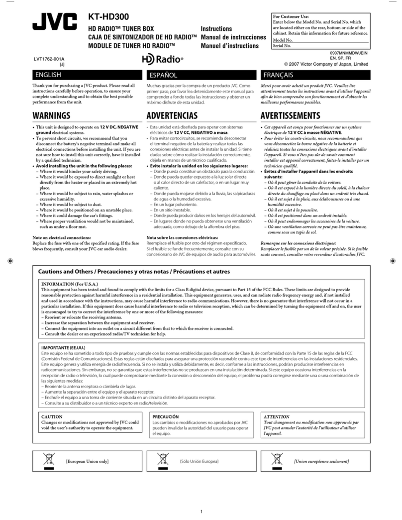
Other JVC Tuner manuals

JVC T-X300 User manual

JVC

JVC T-X300 User manual

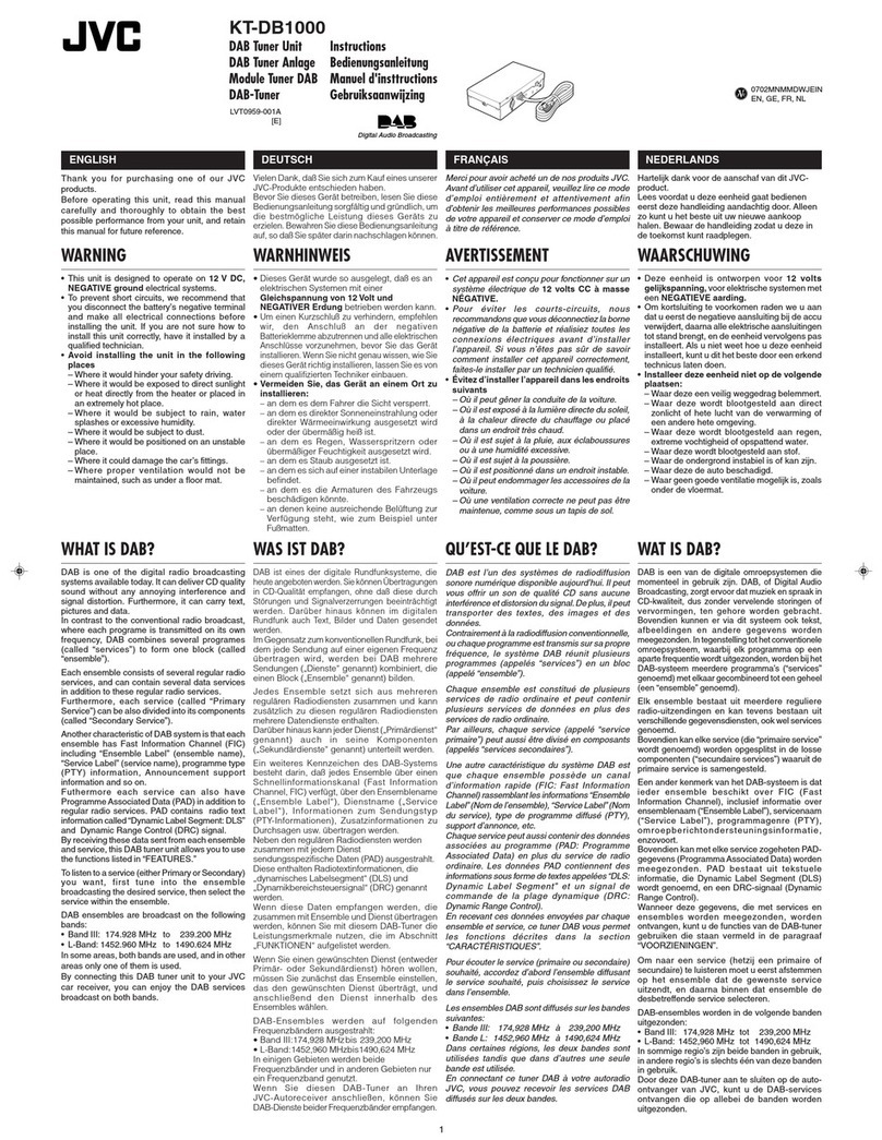
JVC KT-DB1000 User manual

JVC

JVC KT-DB1000 User manual

JVC KT-HD300 - Add-On HD Radio Tuner Works User manual

JVC

JVC KT-HD300 - Add-On HD Radio Tuner Works User manual

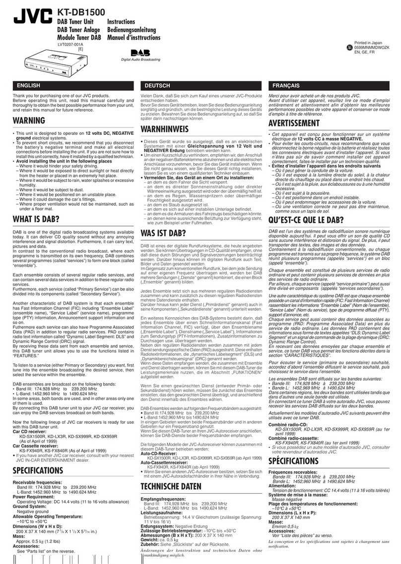
JVC KT-DB1500 User manual

JVC

JVC KT-DB1500 User manual

JVC KV-C1008 User manual

JVC

JVC KV-C1008 User manual

JVC KT-DB1000 User manual

JVC

JVC KT-DB1000 User manual

JVC KT-DB1000 User manual

JVC

JVC KT-DB1000 User manual

JVC KV-C10 User manual

JVC

JVC KV-C10 User manual

Popular Tuner manuals by other brands

Yamaha YT-1100 owner's manual

Yamaha

Yamaha YT-1100 owner's manual

Kenwood KT-57 instruction manual

Kenwood

Kenwood KT-57 instruction manual

Onkyo T-4555 - Radio Tuner instruction manual

Onkyo

Onkyo T-4555 - Radio Tuner instruction manual

Freedom9 Capture 750 Specifications

Freedom9

Freedom9 Capture 750 Specifications

Exposure 2010S2 quick start guide

Exposure

Exposure 2010S2 quick start guide

Qwik Tune QT-12 instructions

Qwik Tune

Qwik Tune QT-12 instructions

Sanyo VA-SW3050LITE instruction manual

Sanyo

Sanyo VA-SW3050LITE instruction manual

ANTUNER AT-100M Quick start manual

ANTUNER

ANTUNER AT-100M Quick start manual

Jameasy Plus user guide

Jameasy

Jameasy Plus user guide

Korg GT-4 owner's manual

Korg

Korg GT-4 owner's manual

SOTABEAMS Micro Z user guide

SOTABEAMS

SOTABEAMS Micro Z user guide

Harman Kardon TU615 owner's manual

Harman Kardon

Harman Kardon TU615 owner's manual

Fender FLASH quick start guide

Fender

Fender FLASH quick start guide

Toa DT-900 instruction manual

Toa

Toa DT-900 instruction manual

Dynalink A 2704B operating instructions

Dynalink

Dynalink A 2704B operating instructions

Palstar AT5K owner's manual

Palstar

Palstar AT5K owner's manual

Snark SN-5 user manual

Snark

Snark SN-5 user manual

Vertex Standard FC-30 installation instructions

Vertex Standard

Vertex Standard FC-30 installation instructions

manuals.online logo
manuals.online logoBrands
  • About & Mission
  • Contact us
  • Privacy Policy
  • Terms and Conditions

Copyright 2025 Manuals.Online. All Rights Reserved.