(No.YA008)1-3
SECTION1
PRECAUTION
1.1SAFETYPRECAUTIONS
(1)Thedesignofthisproductcontainsspecialhardware,
manycircuitsandcomponentsspeciallyforsafety
purposes.Forcontinuedprotection,nochangesshouldbe
madetotheoriginal design unlessauthorizedinwriting by
themanufacturer. Replacementpartsmustbeidenticalto
thoseusedintheoriginalcircuits.Serviceshouldbe
performedbyqualified personnel only.
(2)Alterations of the designor circuitryof theproductsshould
notbemade.Anydesign alterationsoradditions willvoid
themanufacturer'swarrantyandwill furtherrelieve the
manufacturerofresponsibilityforpersonalinjuryor
propertydamageresultingtherefrom.
(3)Manyelectrical and mechanical partsintheproductshave
specialsafety-related characteristics.These
characteristicsareoftennot evidentfromvisual inspection
norcantheprotection affordedbythemnecessarilybe
obtainedbyusingreplacementcomponentsratedfor
highervoltage,wattage,etc.Replacementpartswhich
havethesespecialsafetycharacteristicsareidentified in
thepartslistofServicemanual. Electricalcomponents
havingsuchfeatures areidentifiedbyshadingon the
schematicsandby()onthe partslistinService
manual.Theuseofasubstitutereplacementwhichdoes
nothave thesamesafetycharacteristicsasthe
recommendedreplacementpartshowninthepartslistof
Servicemanual maycauseshock, fire, orotherhazards.
(4) Don'tshort betweenthe LIVEsidegroundand
ISOLATED(NEUTRAL)sidegroundorEARTHside
groundwhenrepairing.
Somemodel'spowercircuitispartlydifferentintheGND.
ThedifferenceoftheGNDisshownby theLIVE:()side
GND,the ISOLATED (NEUTRAL):()sideGNDand
EARTH: ( ) sideGND.
Don'tshortbetweentheLIVEsideGNDand ISOLATED
(NEUTRAL)sideGNDorEARTHsideGNDandnever
measurethe LIVEsideGND and ISOLATED(NEUTRAL)
sideGNDorEARTHsideGND atthesametimewitha
measuringapparatus(oscilloscopeetc.). If above notewill
not bekept, afuseor any partswill bebroken.
(5)If anyrepairhas beenmadetothechassis,it is
recommendedthatthe B1settingshouldbe checkedor
adjusted(SeeB1POWERSUPPLYcheck).
(6)Thehighvoltageapplied tothepicturetubemustconform
withthatspecifiedinServicemanual. Excessive high
voltage cancausean increase inX-Rayemission,arcing
andpossiblecomponentdamage,thereforeoperation
underexcessivehighvoltageconditionsshouldbekept to
aminimum,orshouldbeprevented.Ifseverearcing
occurs,removetheACpowerimmediatelyand determine
thecause by visualinspection (incorrectinstallation,
crackedormelted highvoltageharness,poorsoldering,
etc.).To maintainthe properminimumlevelofsoftX-Ray
emission,componentsinthe highvoltagecircuitry
includingthepicturetube mustbetheexact replacements
oralternativesapprovedby themanufacturerofthe
completeproduct.
(7)Donotcheckhighvoltageby drawinganarc.Use ahigh
voltage meterorahighvoltage probewithaVTVM.
Dischargethepicturetubebeforeattemptingmeter
connection,byconnectingaclipleadtothe ground frame
andconnectingtheotherendofthelead througha10k
2Wresistor totheanode button.
(8)Whenservice isrequired,observetheoriginalleaddress.
Extraprecautionshouldbe giventoassurecorrectlead
dressinthehighvoltage circuit area. Whereashort circuit
hasoccurred,thosecomponentsthat indicateevidenceof
overheatingshouldbereplaced.Alwaysusethe
manufacturer'sreplacementcomponents.
(9) IsolationCheck (SafetyforElectrical Shock Hazard)
Afterre-assemblingthe product, alwaysperforman
isolationcheckontheexposedmetalpartsofthecabinet
(antennaterminals,video/audioinputand outputterminals,
Control knobs,metalcabinet,screwheads,earphonejack,
controlshafts,etc.)tobesuretheproductissafetooperate
without dangerofelectrical shock.
a) DielectricStrengthTest
Theisolationbetween theACprimarycircuitandallmetal
partsexposedtotheuser, particularlyanyexposedmetal
part having areturnpathtothe chassisshouldwithstand a
voltage of 3000VAC(r.m.s.) for aperiod of one second. (.
...Withstandavoltageof1100VAC(r.m.s.)toan
appliancerated upto120V,and3000VAC (r.m.s.)toan
appliancerated200Vormore,foraperiodofone second.)
Thismethodoftestrequiresatestequipmentnotgenerally
foundintheservicetrade.
b) LeakageCurrent Check
PlugtheAClinecorddirectlyintotheACoutlet(donotuse
alineisolationtransformerduringthischeck.).Usinga
"LeakageCurrentTester",measurethe leakage current
fromeachexposedmetalpartofthecabinet, particularly
anyexposedmetalpart havingareturnpathtothe chassis,
toaknowngoodearthground (waterpipe,etc.). Any
leakagecurrent mustnot exceed 0.5mAAC(r.m.s.).
However, intropical area,thismustnotexceed0.2mAAC
(r.m.s.).
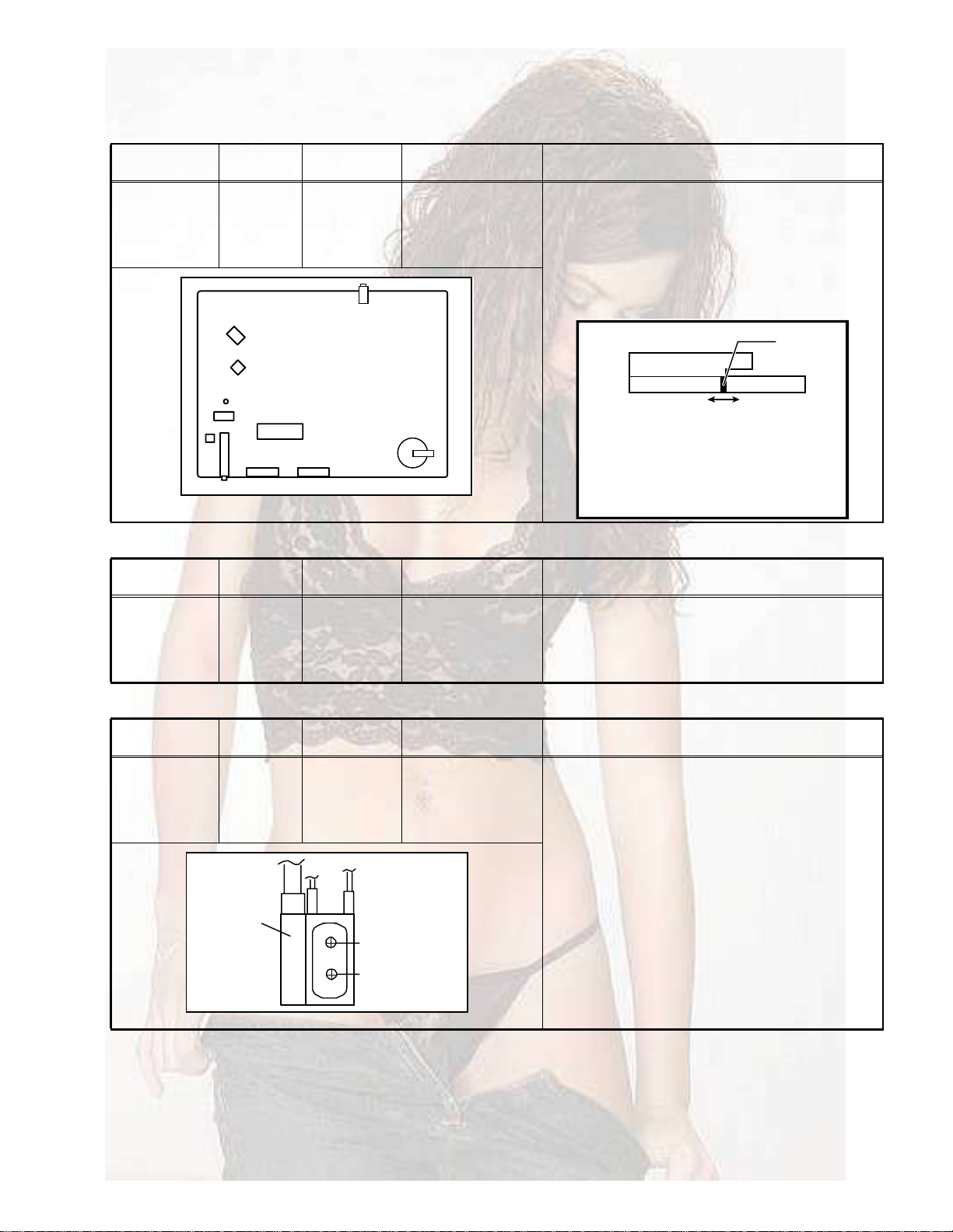
AlternateCheckMethod
PlugtheACline corddirectlyintothe ACoutlet(donot
usealineisolationtransformerduring thischeck.).Use
anACvoltmeterhaving1000 pervolt ormore
sensitivityinthefollowingmanner.Connecta1500
10Wresistorparalleledbya0.15kFAC-typecapacitor
betweenanexposedmetalpart andaknowngoodearth
ground (waterpipe,etc.). MeasuretheACvoltage
across the resistorwiththe ACvoltmeter. Movethe
resistorconnectiontoeachexposedmetalpart,
particularlyanyexposedmetalpart havingareturnpath
tothechassis,andmeasuretheAC voltage acrossthe
resistor.Now,reversetheplugintheACoutletand
repeat eachmeasurement. Anyvoltagemeasured must
notexceed0.75VAC(r.m.s.). Thiscorrespondsto
0.5mAAC(r.m.s.).
However, intropicalarea,thismustnotexceed0.3VAC
(r.m.s.). Thiscorrespondsto0.2mAAC(r.m.s.).
ACVOLTMETER
(HAVING1000/V,
ORMORE SENSITIVITY)
PLACETHIS PROBE
ONEACH EXPOSED
METALPART
150010W
0.15FAC-TYPE
GOODEARTHGROUND


 User manual")