JVC AV-48WP30 User manual

PROJECTION TELEVISION
USER'S GUIDE
For model:
AV-48WP30
IMPORTANT NOTE TO THE CUSTOMER
In the spaces below, enter the model and serial number of your television (locat-
ed at the rear of the television cabinet). Staple your sales receipt or invoice to
the inside cover of this guide. Keep this user's guide in a convenient place for
future reference. Keep the carton and original packaging for future use.
Serial Number LCT1083-001D-A
AV-48WP30 English 3/12/02 2:54 PM Page 1

IMPORTANT SAFETY PRECAUTIONS
WARNING: TO PREVENT FIRE OR SHOCK HAZARDS, DO NOT
EXPOSE THIS TV SET TO RAIN OR MOISTURE.
CAUTION: TO INSURE PERSONAL SAFETY, OBSERVE THE
FOLLOWING RULES REGARDING THE USE OF
THIS UNIT.
1) Operate only from the power source specified on the unit.
2) Avoid damaging the AC plug and power cord.
3) Avoid Improper installation and never position the unit where good ven-
tilation is unattainable.
4) Do not allow objects or liquid into the cabinet openings.
5) In the event of trouble, unplug the unit and call a service technician. Do
not attempt to repair it yourself or remove the rear cover.
Changes or modifications not approved by JVC could void the warranty.
* When you don’t use this TV set for a long period of time, be sure to dis-
connect both the power plug from the AC outlet and antenna for your
safety.
* To prevent electric shock do not use this polarized plug with an exten-
sion cord, receptacle or other outlet unless the blades can be fully insert-
ed to prevent blade exposure.
CAUTION:To reduce the risk of electric shock.
Do not remove cover (or back).
No user serviceable parts inside.
Refer servicing to qualified service personnel.
The lightning flash with arrowhead symbol,
within an equilateral triangle is intended to
alert the user to the presence of uninsulated
“dangerous voltage” within the product’s
enclosure that may be of sufficient magnitude
to constitute a risk of electric shock to per-
sons.
The exclamation point within an equilateral tri-
angle is intended to alert the user to the pres-
ence of important operating and maintenance
(servicing) instructions in the literature accom-
panying the appliance.
RISK OF ELECTRIC SHOCK
DO NOT OPEN
CAUTION
AV-48WP30 English 3/12/02 2:54 PM Page 2

IMPORTANT SAFEGUARDS
CAUTION:
Please read and retain for your safety.
Electrical energy can perform many useful functions.This TV set has been engineered and
manufactured to assure your personal safety. But improper use can result in potential elec-
trical shock or fire hazards! In order not to defeat the safeguards incorporated in this TV set,
observe the following basic rules for its installation, use and servicing.
And also follow all warnings and instructions marked on your TV set.
INSTALLATION
1) Your TV set is equipped with a polarized AC line plug (one blade of the plug is wider than
the other).
This safety feature allows the plug to fit into the power outlet only one way. Should you be
unable to insert the plug fully into the outlet, try reversing the plug.
Should it still fail to fit, contact your electrician.
2) Operate the TV set only from a power source as indicated on the TV set or refer to the oper-
ating instructions for this information. If you are not sure of the type of power supply to your
home, consult your TV set dealer or local power company. For battery operation, refer to the
operating instructions.
3) Overloaded AC outlets and extension cords are dangerous, and so are frayed power cords
and broken plugs. They may result in a shock or fire hazard. Call your service technician for
replacement.
4) Do not allow anything to rest on or roll over the power cord, and do not place the TV set
where power cord is subject to traffic or abuse.This may result in a shock or fire hazard.
5) Do not use this TV set near water — for example, near a bathtub, washbowl, kitchen sink,
or laundry tub, in a wet basement, or near swimming pool, etc.
6) If an outside antenna is connected to the TV set, be sure the antenna system is grounded
so as to provide some protection against voltage surges and built-up static charges. Section
810 of the National Electrical Code provides information with respect to proper grounding of
the mast and supporting structure, grounding of the lead-in wire to an antenna discharge
unit, size of grounding conductors, location of antenna discharge unit, connection require-
ments for the grounding electrode.
(POLARIZED-TYPE)
IMPORTANT RECYCLING INFORMATION
This product utilizes both a Cathode Ray Tube (CRT) and other com-
ponents that contain lead. Disposal of these materials may be regu-
lated in your community due to environmental considerations. For
disposal or recycling information, please contact your local authori-
ties, or the Electronic Industries Alliance: http://www.eiae.org
AV-48WP30 English 3/12/02 2:54 PM Page 3

7) An outside antenna system should not be located in the vicinity of overhead power lines or
other electric light or power circuits, or where it can fall into such power lines or circuits.
When installing an outside antenna system, extreme care should be taken to keep from
touching such power lines or circuits as contact with them might be fatal.
8) TV sets are provided with ventilation openings in the cabinet to allow heat generated during
operation to be released.
Therefore:
— Never block the bottom ventilation slots of a portable TV set by placing it on a bed, sofa,
rug, etc.
— Never place a TV set in a “built-in” enclosure unless proper ventilation is provided.
— Never cover the openings with a cloth or other material.
— Never place the TV set near or over a radiator or heat register.
9) To avoid personal injury:
— Do not place a TV set on a sloping shelf unless properly secured.
— Use only a cart or stand recommended by the TV set manufacturer.
— Do not try to roll a cart with small casters across thresholds or deep pile carpets.
— Wall or shelf mounting should follow the manufacturer’s instructions, and should use a
mounting kit approved by the manufacturer.
USE
10) Caution children about dropping or pushing objects into the TV set through cabinet open-
ings. Some internal parts carry hazardous voltages and contact can result in a fire or elec-
trical shock.
11) Unplug the TV set from the wall outlet before cleaning. Do not use liquid or an aerosol
cleaner.
12) Never add accessories to a TV set that has not been designed for this purpose. Such addi-
tions may result in a hazard.
EXAMPLE OF ANTENNA GROUNDING
AS PER NATIONAL ELECTRICAL CODE
AV-48WP30 English 3/12/02 2:54 PM Page 4

13) For added protection of the TV set during a lightning storm or when the TV set is to be left
unattended for an extended period of time, unplug it from the wall outlet and disconnect
the antenna.This will prevent damage to product due to lightning storms or power line
surges.
14) A TV set and cart combination should be moved with care. Quick stops, excessive force,
and uneven surfaces may cause the TV set and cart combination to overturn.
SERVICE
15) Unplug this TV set from the wall outlet and refer servicing to qualified service personnel
under the following conditions:
A.When the power cord or plug is damaged or frayed.
B. If liquid has been spilled into the TV set.
C. If the TV set has been exposed to rain or water.
D. If the TV set does not operate normally by following the operating instructions. Adjust
only those controls that are covered in the operating instructions as improper adjust-
ment of other controls may result in damage and will often require extensive work by a
qualified technician to restore the TV set to normal operation.
E. If the TV set has been dropped or damaged in any way.
F. When the TV set exhibits a distinct change in performance — this indicates a need for
service.
16) Do not attempt to service this TV set yourself as opening or removing covers may expose
you to dangerous voltage or other hazards. Refer all servicing to qualified service person-
nel.
17) When replacement parts are required, have the service technician verify in writing that the
replacement parts he uses have the same safety characteristics as the original parts. Use
of manufacturer’s specified replacement parts can prevent fire, shock, or other hazards.
18) Upon completion of any service or repairs to this TV set, please ask the service technician
to perform the safety check described in the manufacturer’s service literature.
19) When a TV set reaches the end of it’s useful life, improper disposal could result in a
picture tube implosion. Ask a qualified service technician to dispose the TV set.
20) Note to CATV system installer.
This reminder is provided to call the CATV system installer’s attention to Article 820-40 of
the NEC that provides guidelines for proper grounding and, in particular, specifies that the
cable ground shall be connected to the grounding system of the building, as close to the
point of cable entry as practical.
AV-48WP30 English 3/12/02 2:54 PM Page 5

Table of Contents
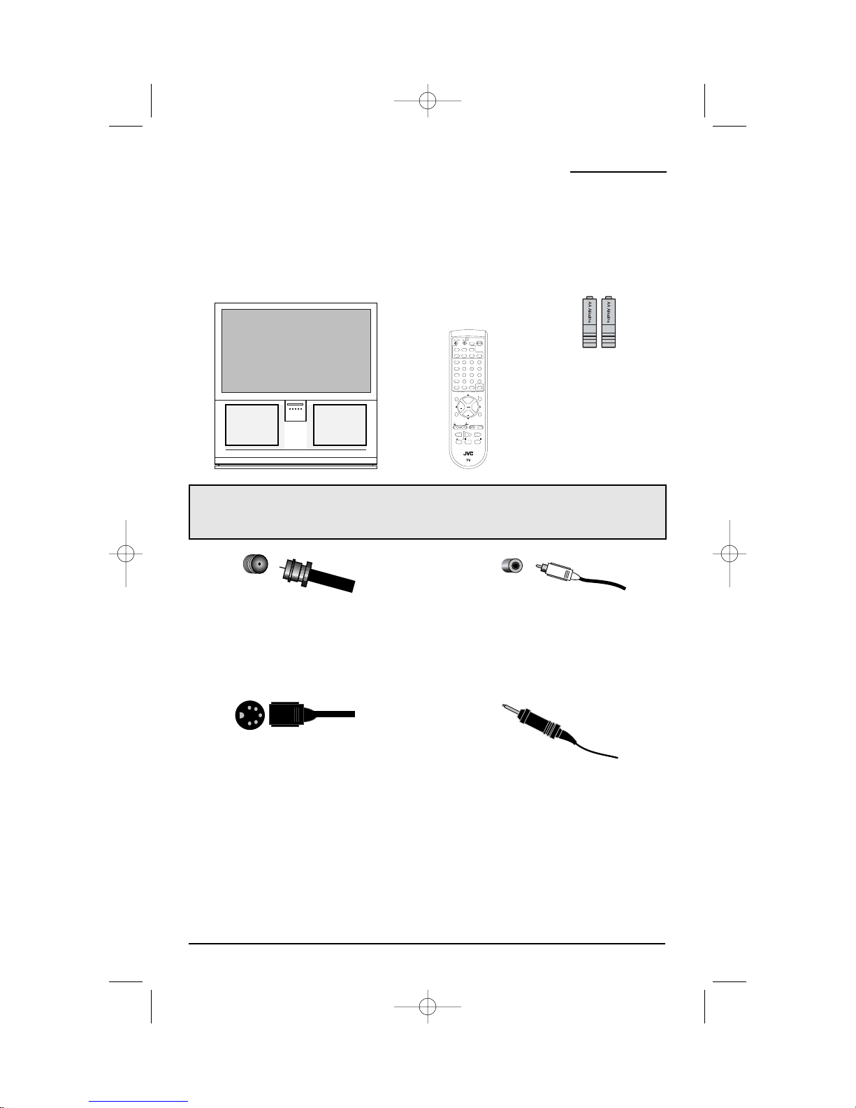
UnpackingYourTelevision . . . 8
Quick Setup . ...............9
CONNECTIONS . ........12
Front Panel Diagram . ...........12
Rear Panel Diagram . ..........12
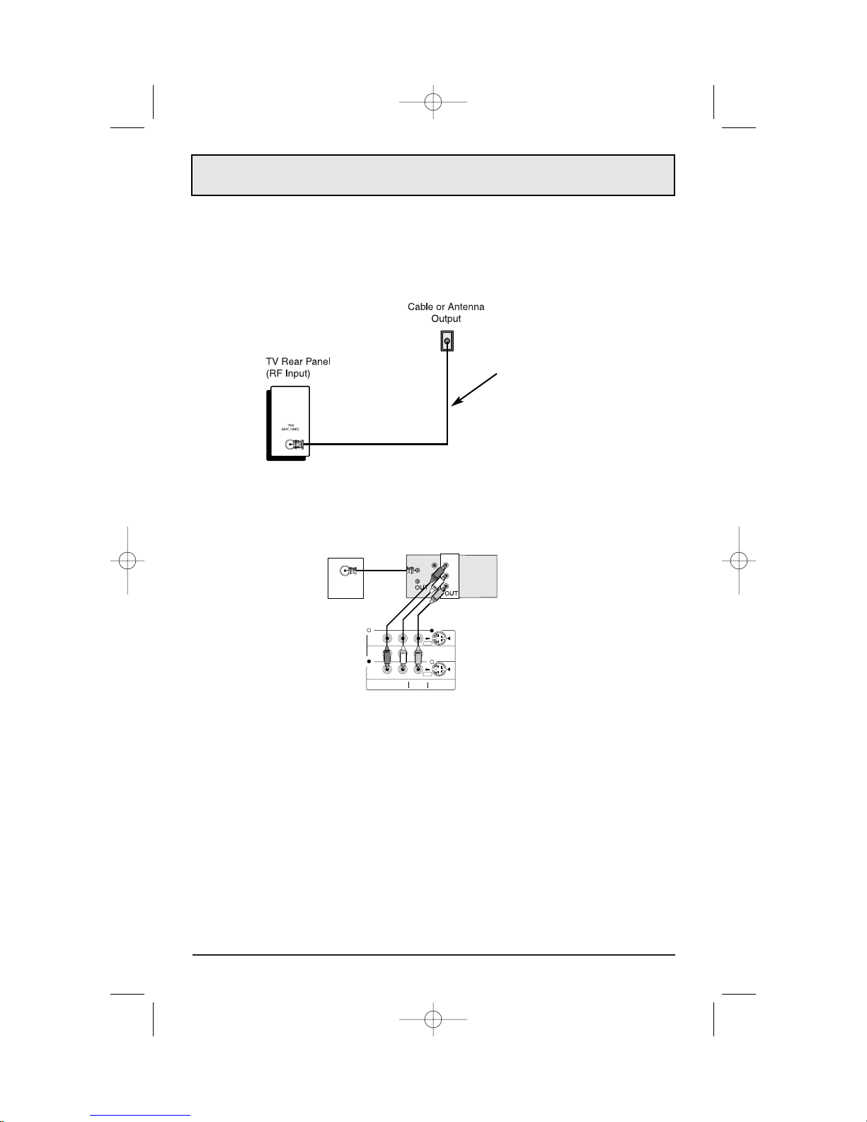
Connecting to Cable or an Antenna . ...13
Cable and VCR Connections . .....14
Connecting to a DVD Player,
DTV Decoder and D-VHS . ........15
Connecting to a Digital
TV Receiver w/HDCP . ..........16
Connecting to a DVD Player . .......17
Connecting to JVC AV Compu Link III . . . 18
Connecting Devices to the Front Panel . . 19
Connecting to an External Amplifier . . . 20
Connecting to the Surround Amplifier . . . 20
Remote Control . ........21
Installing the batteries . . . . . . . . . . . 21
Remote Control Basics . .........21
Remote Programming . ....22
Setting CATV, VCR, and DVD Codes . . . 22
Cable Box or Satellite Setup . ......22
VCR Setup . ................23
DVD Setup . ................24
Search Codes . ..............25
Onscreen Menus . .......26
Onscreen Menu System . .........26
Using the Onscreen Menus . .......27
Plug In Menu . ..............28
Language...........28
Auto Tuner Setup .......29
Set Clock . . . . . . . .....30
Auto . ........30
Manual . .......30
Finish..............30
Initial Setup . ...............31
Auto Tuner Setup . .......31
Channel Summary . ......32
Channel Summary – Lock . . . 32
Channel Guard Message . ...32
6
Onscreen Menus (Continued)
V-Chip . ..................33
US Rating System . ......33
Viewing Guidelines . ......33
MPAA Ratings . ........34
Set Ratings Guidelines . ....35
To SetTV Ratings Levels . ...35
To Set Movie Ratings Levels . . 36
Unrated Programs . ......36
Warning Message . ......36
CanadianV–Chip Ratings . . . 37
Set Lock Code . ........38
Initial Setup 2 . ..............39
Language . . . . . . ......39
Closed Caption . ........39
Front Panel Lock . .......40
Auto Shut Off . .........41
Digital–In . ...........41
Picture Adjust . ..............42
Tint . ..............42
Color . .............42
Picture . ............43
Bright . .............43
Detail . .............43
Picture Adjust 2 . .............44
Color Temperature . ......44
Dig. Noise Clear . ........44
Noise Muting . .........44
Sound Adjust . ..............45
Bass . .............45
Treble ..............45
Balance . ............45
MTS . ..............46
Sound Advice . .........46
Clock /Timers . ..............47
Clock Timers . .........47
Set Clock . . . .........47
On/Off Timer . ........47
Setting the On/Off Timer . . . 48
Initial Setup 3 . ..............49
Vertical Position . . .......49
Center Ch Input . .......50
XDS ID .............50
Power Indicator . . . . .....50
Aspect . ..................51
Aspect . ............51
Aspect Ratios . .........51
Adjusting CRT Color Convergence . ...52
AV-48WP30 English 3/12/02 2:54 PM Page 6

Table of Contents
7
Button Functions . .......53
SPLIT . ..................53
SWAP ...................53
FREEZE . .................53
SELECT . .................53
ENTER . .................53
INDEX . ..................54
POP . ...................54
MENU . ..................55
EXIT . ...................55
DISPLAY . . . . . .............55
SLEEP TIMER . ..............55
BBE . ...................56
HYPER SURROUND . ..........56
MUTING . . . ...............56
VIDEO STATUS . .............56
NATURAL CINEMA . ...........56
ASPECT . .................56
NUMBER BUTTONS – 10 KEY PAD . . . 57
100+ BUTTON . ..............57
RETURN+ . ................57
V-CHIP . ..................57
INPUT . ..................58
MENU (On TV’s Front Panel) . ......58
LIGHT . ..................58
VCR BUTTONS . .............59
DVDBUTTONS . .............59
TV/CATV SWITCH . ............59
VCR/DVD SWITCH . . . . ........59
Troubleshooting . .......60
Appendix A . ..........62
LimitedWarranty . . . . . . . . 63
Authorized Service Centers . . 65
Specifications . ........66
AV-48WP30 English 3/12/02 2:54 PM Page 7

8
2 AA Batteries
1 Television 1 Remote Control
Thank you for your purchase of JVC’s model AV-48WP30 Color Television. Before you begin
setting up your new television, please check to make sure you have all of the following items.
In addition to this guide, your television box should include:
Once you have unpacked your television, the next step is to connect it to your antenna/cable
or satellite system and to connect the audio/video devices you want to use with your televi-
sion. To make these connections you will use plugs like the ones illustrated below.
A/V Input Plug
RF Connectors
Used to connect a
coaxial cable from an
external antenna or Cable
TV system.
Used to make video con-
nections with VCRs,
DVDs, Camcorders, etc
(optional).
Used to connect JVC AV
Compu Link
capable components for
an automated home the-
ater.
Used to connect
audio/video devices like
VCRs, DVD players, stereo
amplifiers, game consoles,
etc.
S-Video Plug AV Compu Link Cable
We recommend that before you start using your new television, you read your entire User’s
Guide so you can learn about your new television’s many great features. But if you’re anxious
to start using your television right away, a quick setup guide follows on the next three pages.
UnpackingYour Television
JVC
RM-C322G
POWER
DISPLAY
SLEEP TIMER
LIGHT
INPUT
SPLIT POP
NATURAL CINEMA
FREEZE SWAP
MULTI SCREEN
SELECT
INDEX
ASPECT
ENTER
1
7
4
100+
3
9
6
RETURN+
MUTING
MENU
V CHIP
EXIT
2
8
0
5
+
CH
VOL VOL
+
CH
REC
OPEN/CLOSE STILL/PAUSE
STOP PAUSE
PLAY FFREW
TV
CATV VCR DVD
VCR CHANNEL
PREV NEXT
TV/VCR
VCR/DVD
POWER
BBE
V. STATUS HYPERSUR.
AV-48WP30 English 3/12/02 2:54 PM Page 8

9
Slide the cover on the back of the remote down towards the bottom of the remote control.
Insert two batteries (included) carefully noting the “+” and “–” markings, placing the “–” end in
the unit first. Slide the cover back into place.
Getting Started
These quick setup pages will provide you, in three easy steps, with the basic information you
need to begin using your new television right away. This information includes basic instructions
on operating your remote control, making a simple cable/antenna and optional VCR connection
and, finally, information on programming your television's Auto Tuner.
If you have questions, or for more detailed information on any of these steps, please consult
other sections of this manual.
Step One - The Remote Control
The remote control is the key to operating your television's many great features. Before you
can operate your remote control, you first need to install the batteries (included).
Basic Operation
Turn the television on and off by pressing the POWER button at the top right corner of the
remote.
The four key feature buttons at the center of the remote can be used for basic operation of the
television. The top and bottom buttons will scan forward and back through the available chan-
nels. The right and left buttons will turn the volume up or down. These buttons are also
marked with four arrows and are also used with JVC's onscreen menu system. You will need to
use these buttons later in the Quick Setup.
The next step is to connect your television to an antenna or cable.
POWER
Power Button Key Feature Buttons
Proceed to Step Two
Quick Setup 1
AV-48WP30 English 3/12/02 2:54 PM Page 9

10
Cable/RF connector
Step Two - Making Basic Connections
Next you will need to connect your television to an antenna, VCR or cable system. The most
basic VCR and antenna/cable connection is shown below. For more detailed connections, such
as ones where a cable box is required, or connecting with a combination of a cable box and
VCR, home stereo system, etc., see pages 12 to 20.
1) Connect an RF Cable from the wall outlet into the RF Cable In on the back of the TV.
Quick Setup 2
1) Connect the Red Cable from VCR Audio Output into the Red TV Audio In.
2) Connect the White Cable from VCR Audio Output into the White TV Audio In.
3) Connect the Yellow Cable from VCR Output into theYellow TV Video In, OR Connect an RF
Cable from VCR RF Cable Out into the RF Cable In on the back of the TV.
NOTE:
• White,Yellow and Red are the most common colors for VCR Cables. Some models may vary
in color. Please consult the user’s manual for your VCR Player for more information.
• See page 23 for instructions on programming your remote control to operate the basic func-
tions of your VCR Player.
Connecting to a VCR
Proceed to Step Three
VCR
IN
IN
WALL
CABLE or ANTENNA OUT
OVER
OVER
AUDIO
R L VIDEO S-VIDEO
BACK of TV
R
L
V
RED
WHITE
YELLOW
AV-48WP30 English 3/12/02 2:54 PM Page 10

Press the
"#
buttons to move to AUTO TUNER SETUP
Press the
$%
buttons to begin AUTO TUNER SETUP
$%
To choose CABLE (if you are connected to a cable system) or AIR (if you use
an antenna)
"#
To move to START
$%
To start Auto Tuner Setup
The Auto Tuner will now memorize all of the clear, active channels your television can
receive. This will take roughly one or two minutes.
NOW
PROGRAMMING!
48
Step Three - The Plug In Menu
When you turn your television on for the first time, the Plug In Menu will appear. This menu
sets some of the basic settings for your television. A complete description of the Plug In Menu
can be found starting on page 28. We recommend you complete the Plug In Menu items
before you start using your television. To begin watching your television right away you only
need to run the Auto Tuner Setup. This lets your television learn the channels it is able to
receive clearly. To run the Auto Tuner Setup, follow the steps below.
The Auto Tuner is finished when the message PROGRAMMING OVER! appears on screen.
Your Quick Setup is now complete. You can now begin watching your television, or you can
continue on in this guide for more information on connecting audio/video devices, programming
your remote control, or using the JVC onscreen menu system to customize your television
viewing experience.
The Quick Setup is complete
Quick Setup 3
PLUG IN MENU
AUTO TUNER SETUP
SET CLOCK
FINISH
OPERATE BY EXIT BY
SELECT BY
LANGUAGE ENG FRE SPA
EXIT
AUTO TUNER SETUP
OPERATE BY EXIT BY
SELECT BY EXIT
TUNER MODE CABLE
START
STOP
11
AV-48WP30 English 3/12/02 2:54 PM Page 11

Connections
Front Panel Diagram
Rear Panel Diagram
12
JVC
S-VIDEO
OVER
VIDEO L / MONO
AUDIO
R
INPUT4
AV-48WP30 English 3/12/02 2:54 PM Page 12

13
1) Connect an RF Cable from the wall outlet into the RF Cable In on the Cable Box.
2) Connect an RF cable from the Cable Out on the cable box into the RF Cable In on the back
of the TV.
NOTE:
• Please see page 54 for more information on using the POP feature with a cable box.
Connecting to a Cable Box
Diagram #2
Connections
There are three basic types of antenna or cable connections:
• If you have an antenna or have a cable system that does not require you use a cable box
to select channels, please refer to Diagram #1.
• If you have a cable system that requires the use of a cable box to access all the
channels, please refer to Diagram #2.
• If you have a cable system that requires the use of a cable box to access certain
premium channels, but not “basic” cable channels, please refer to Diagram #3.
•For your convenience, connection to a VCR is also shown in the following diagrams. A
VCR is not necessary for operation of the television or Picture OUT or Picture POP
function. You may omit the VCR from your connections if you wish.
• For instructions on connecting a VCR only, please see the Quick Setup on page 9.
• For information on using POP, please see page 54.
Connecting to Cable or an Antenna
Diagram #1
Cable/RF connector
1) Connect an RF Cable from the wall outlet into the RF Cable In on the back of the TV.
AV-48WP30 English 3/12/02 2:54 PM Page 13

14
Connections
Connecting to a Cable Box and VCR
Diagram #3
1) Connect an RF Cable from the wall outlet into the RF Cable Box In.
2) Connect an RF Cable from the Cable Box Out into the VCR In.
3) Connect an RF Cable from the VCR Out into the RF In on the back of the TV.
4) Connect the Red Cable from VCR Right Audio Output into the Red TV Audio In.
5) Connect the White Cable from VCR Left Audio Output into the White TV Audio In.
6) Connect the Yellow Cable from VCR Output into theYellow TV Video In, OR Connect an
S-Video Cable from VCR S-Video Out into the S-Video In on the back of the TV.
NOTE:
• White,Yellow and Red are the most common colors for VCR Cables. Some models may vary
in color. Please consult the user’s manual for your VCR Player for more information.
• See page 23 for instructions on programming your remote control to operate the basic func-
tions of your VCR Player.
The connection diagrams are intended to show some basic general connections.
Some cable companies may require special connections to properly use your televi-
sion or 2-tuner MULTI SCREEN function. If you follow these diagrams and either the
television or PIP does not work properly, contact your local cable operator for more
connection information. Please see page 54 for more information on the POP feature.
AV-48WP30 English 3/12/02 2:54 PM Page 14

S
AUDIO OUT
R L
OVER
OVER
INPUT 3
INPUT 2
PBPB
PRPR
YY
COMPONENT VIDEO
AUDIO
R L VIDEO S-VIDEO
PR
PB
Y
BACK of TV
Your AV-48WP30 television is HDTV and SDTV-Ready.This means it can display High
Definition television images when connected to a digital television receiver*.DTV Decoders are
available separately. For best image quality, we recommend using a DTV Decoder which uses
Component Video (Y, PB, PR) Output to connect to the television.The diagram below shows
how to connect a DTV Decoder with using the television’s Component Video-in jacks.
1) Connect Green cable out from the DTV Decoder “Y” Video Output, in to TV “Y” Component
Input.
2) Connect Blue cable out from the DTV Decoder “PB” Video Output, in to TV “PB” Component
Input.
3) Connect Red cable out from the DTV Decoder “PR” Video Output, in to TV PR” Component
Input.
4) Connect White Audio cable out the DTV Decoder Left Audio Output, in to TV Left Audio
Input.
5) Connect Red Audio cable out the DTV Decoder Right Audio Output, in to TV Right Audio
Input.
Make sure you use the same numbered input for both the Component Input and Audio
Input. For instance, if you use Component Input 2, also use Audio Input 2.
• Green, blue and red are the most common colors for Component Video cables. Some models
may vary colors, please consult the user’s manual for your DTV Decoder for more
information.
• Be careful not to confuse the red Component Video cable with the red audio cable. It is best
to complete one set of connections (Audio or Video) before starting the other to avoid acci-
dentally switching the cables.
* Notes About HDTV Operation
The AV-48WP30 can display 480p, 480i, 1080i and 720p signal formats using the
Component Video Inputs. It cannot display 1080p signal. For High Definition (HDTV) picture
display a DTV decoder must be connected to the TV.
Connections
Connecting a DVD Player, DTV Decoder, and D-VHS
Green
Blue
Red
DTV Decoder
15
Component Connection
S–Video Connection
AV-48WP30 English 3/12/02 2:54 PM Page 15

Connections
Connecting to a Digital TV Receiver w/HDCP
By inputting a high bandwidth Digital Content Protection High Definition picture source to the
Digital-In terminal of this television, high-definition pictures can be displayed on the screen in
their digital form. (This terminal is for use in the future when high bandwidth Digital Content
Protection DTV decoders and DVD players and D-VHS are put on the market.)
16
1) Connect the DTV digital RGB output terminal to the digital input terminal of the television,
and then tighten the 2 screws.
2) Connect the DTV decoder left audio output to the DIGITAL-IN left audio input.
3) Connect the DTV decoder right audio output to the DIGITAL-IN right audio input.
• The Digital-In terminal can only be used with 1080i, 720p and 480p picture signals. Set the
DTV decode Digital-Out terminal output setting to 1080i, 720p or 480p. For detailed informa-
tion, refer to the DTV decoder instruction manual. If you can not display the picture because
your DTV decoder does not have a Digital-Out terminal output setting, use the component
Video Input (or the S-Video Input or Video Input). (Refer to page 15) In this case the picture
will be displayed as an analog signal.
• The Digital-In terminal is not compatible with the picture signal of a personal computer.
• Use a DVI-D Single Link 19-pin cable (commercially available) in order to digitally connect
the television with a DTV decoder.
If 480p signals (640x480 or 720x480) are displayed on the screen, the horizontal balance may
be slightly shifted. In cases such as this, the horizontal balance can be adjusted by accessing
“DIGITAL-IN” in the INITIAL SETUP Menu. (Refer to page 41.)
DIGITAL IN
AUDIO OUT
DIGITAL OUT
LR
AUDIO R L
After the connections
have been made,
tighten the screw to
secure the cables.
DTV decoder
AV-48WP30 English 3/12/02 2:54 PM Page 16

Connections
Connecting a DVD Player
You can use the Component Video input jacks to connect a DVD player to your television.To
connect a DVD player, please follow the steps listed below.
1) Connect Green cable out from the DVD Player “Y” Video Output, in to TV “Y” Component
Input.
2) Connect Blue cable out from the DVD Player “PB” Video Output, in to TV “PB” Component
Input.
3) Connect Red cable out from the DVD Player “PR” Video Output, in to TV PR” Component
Input.
4) Connect White Audio cable out the DVD Player Left Audio Output, in to TV Left Audio Input.
5) Connect Red Audio cable out the DVD Player Right Audio Output, in to TV Right Audio
Input.
Make sure you use the same numbered input for both the Component Input and Audio
Input. For instance, if you use Component Input 3, also use Audio Input 3.
• Green, blue and red are the most common colors for Component Video cables. Some models
may vary colors, please consult the user’s manual for your DVD Player for more information.
• Be careful not to confuse the red Component Video cable with the red audio cable. It is best
to complete one set of connections (Audio or Video) before starting the other to avoid acci-
dentally switching the cables.
• If your DVD player does not have a Component Video output, you may connect it using an
S-Video cable. See your DVD player’s owners manual for more information on making an
S-Video connection.
Note:
If you want to display the picture from the DVD player when using split screens, also connect
the S-Video cable.
17
S
AUDIO OUT
R L
OVER
OVER
INPUT 3
INPUT 2
PBPB
PRPR
YY
COMPONENT VIDEO
AUDIO
R L VIDEO S-VIDEO
PR
PB
Y
BACK of TV
Component Connection
S–Video Connection
Green
Blue
Red
AV-48WP30 English 3/12/02 2:54 PM Page 17

Connections
Connecting to AV Compu-Link III
JVC’s AV Compu Link III feature makes playing video tapes totally automatic. Simply insert a
pre-recorded tape* into your JVC-brand VCR and the VCR will automatically turn on and begin
playback. At the same time, using the AV Compu Link, the VCR sends a signal to the television
telling it to turn on and switch to the proper video input to watch a video tape.
• The AV Compu Link cable may be included with the JVC AV Compu Link accessory you wish
to connect. If it is not, contact an authorized JVC Service Center for part # EWP 805-012.
• AV Compu Link III can only be used with JVC-brand products.
To Connect: Plug one end of the AV Compu Link cable into the AV Compu Link input on your
VCR or other Compu Link device. Plug the other end of the AV Compu Link cable into the AV
Compu Link input at the rear of the television.
Notes:
* In order for the VCR playback to begin automatically, the recording tabs must be removed
from the VHS tape. If the tab is in place, automatic switching will occur when you push the
VCR’s PLAY button.
• The AV Compu Link cable has a male 3.5 mm (mono) plug on each end.
• If your JVC-brand VCR has “A Code/B Code Remote Control Switching” (see your VCR’s
instruction book), using VCR A Code will switch the TV to input 1. If you use Input 1 for
video input from your cable box, use VCR B Code to select the TV Video Input 2.
• To connect a JVC HiFi receiver or amplifier for a completely automated home theater, see
the HiFi’s connection instructions for detailed connection information.
• AV COMPU LINK III is compatible with all JVC AV COMPU LINK III devices
• The AV-48WP30 can also receive Compu-Link signals from a DVD player. For details on
operating a DVD player with AV Compu Link, please see your DVD player’s owners
manual.
18
AV COMPULINK III
IN
IN
VCR
AV
Compu
Link
Swap
AV-48WP30 English 3/12/02 2:54 PM Page 18

Connections
A set of inputs (Input-4) are provided for your convenience on the front panel of the
AV-48WP30.The inputs are located behind the door at the center of the front panel below the
indicator lights.These inputs are designed for the easy connection of devices like camcorders
or game consoles which are not permanent parts of your home entertainment center.
Connecting Devices to the Front Panel Inputs
To access the front panel jacks, gently pull the tab on the door torwards you to open it.
To connect a device like a camcorder:
1) Connect the yellow video cable from the device’s Video Output jack to the TV’s Video Input
jack, or connect an S-Video cable from the camcorder’s S-Video Output to the TV’s S-Video
Input.
2) Connect the white (or black) audio cable from the device’s Left Audio Output jack to the TV’s
Left Audio Input jack.
3) Connect the red audio cable from the device’s Right Audio Output jack to the TV’s Right
Audio Input jack.
• If you are connecting a mono sound device it will have only one audio out jack. Connect it to
the TV’s left audio input jack.
• The device will be available on Input 4 on the Input Menu (see page 58) if the connection shown
above is used.
• Please consult your camcorder or other device’s owners manual for more information on its
operation.
19
— OR —
AV-48WP30 English 3/12/02 2:54 PM Page 19

20
Connections
Connecting to an External Amplifier
1) Connect the White Audio Cable from the TV’s Left Audio Output Jack to the Amplifier’s Left
Audio Input Jack.
2) Connect the Red Audio Cable from the TV’s Right Audio Output Jack to the Amplifier’s Right
Audio Input Jack.
BLACK
RED
FRONT FRONT SURROUND
Center Speaker Out
1) Connect the BLACK speaker cable from the TV’s SPEAKER INPUT terminal to the
surround amplifier’s center speaker output terminal.
2) Connect the RED speaker cable from the TV’s SPEAKER INPUT terminal to the
surround amplifier’s center speaker output terminal.
Connecting to the Surround Amplifier
AV-48WP30 English 3/12/02 2:54 PM Page 20
Other manuals for AV-48WP30
3
Table of contents
Other JVC TV manuals

JVC
JVC AV-28H5BU User manual

JVC
JVC I'Art Pro AV-32S565 User manual

JVC
JVC AV28BT7EEB User manual

JVC
JVC AV-27D303 User manual

JVC
JVC AV-21V531 User manual

JVC
JVC AV-28Z25 User manual

JVC
JVC HD-56FH97 - 56" Rear Projection TV User manual

JVC
JVC AV-28KH1BUF User manual

JVC
JVC AV-20NX3 User manual

JVC
JVC AV-28F3SJ User manual