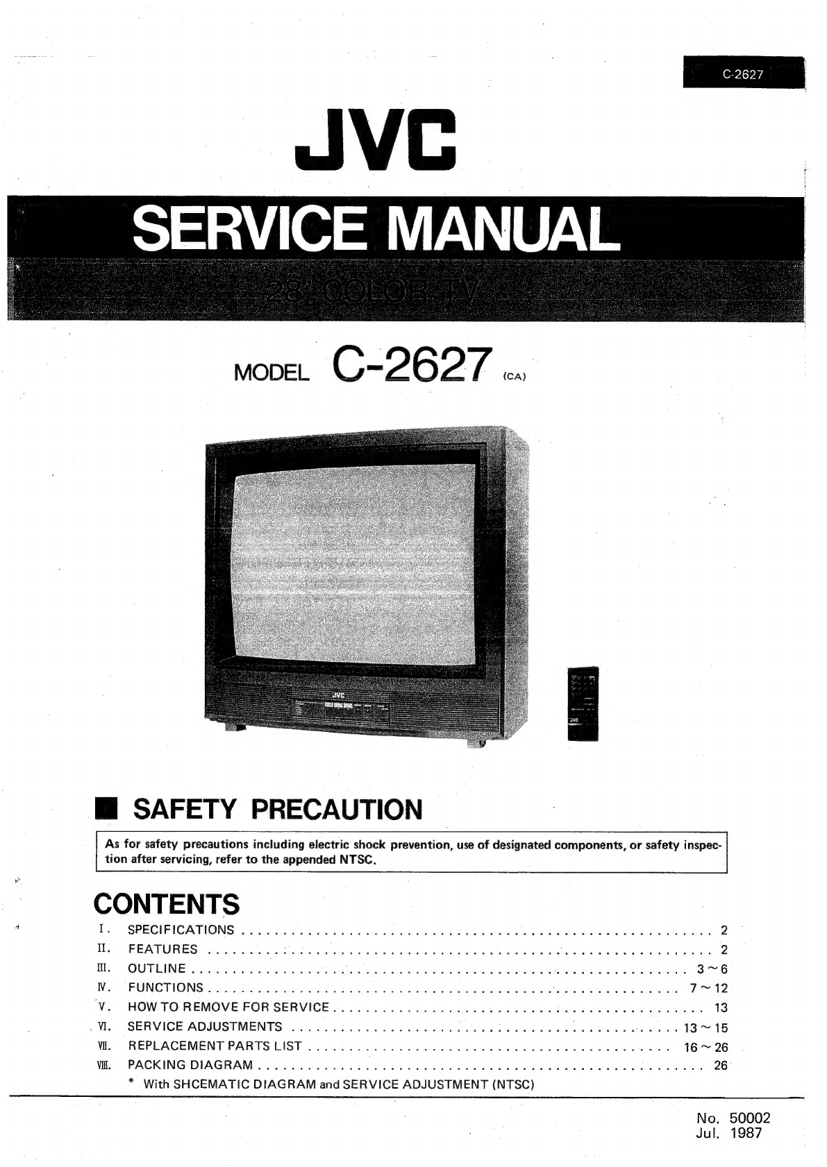
JVC C-2627 User manual

C-2627
Mi
SAFETY
PRECAUTION
As
for
safety
precautions
including
electric
shock
prevention,
use
of
designated
components,
or
safety
inspec-
tion
after
servicing,
refer
to
the
appended
NTSC.
CONTENTS
—
:
.
SPECIFICATIONS
..........
wsihicoa
kame
eoe
ec
aaet
Mc
lenln
Sat
wawlese
saree
OTT
S
ee:
Hs
HEPAT
URES?
sacctpcss
ocatSs
deat
a
2k
Ga
aor
elocne
iad
bi
Hed
eh
tates
ome
fecal?
MH.
OUTLINE
...........-..000e-
Ce
htat
hese
Bigs
Patch
GUL
rasan
hee
a
A
ep
aha
ee
kasd
tide
3~6
WV.
‘FUNCTIONS
.
deiise
nt
Me
Disab
ented
oe
eee
Sie
Sere
aa
Sen
a
Mints
cohen
ately
MND
V.
HOWTO
REMOVE
FORSERVICE.....
assets
a
tehdu
em
cine
kets
Mame
Ae
oes
kad’
i
13
_W..
SERVICE
ADJUSTMENTS
..........0000eeeeeeeee
yee
eee
ede
ated
eee
19
™
15
WI.
REPLACEMENT
PARTSLIST...........-..-.
Piste
atte
ates
ub
Welecedss-
1626
Wi.
PACKING
DIAGRAM
.
wih
ewe
Sd
das
6
send
nten
nae
tocst
2a
fRateasd:
as
tice
kloan
26
*
With
SHCEMATIC
DIAGRAM
and
SERVICE
ADJUSTMENT
(NTSC)
No.
50002
Jul.
1987

67.0
cm(W)
x
54.5
cm(D)
x
63.4
cm(H)
37
kg
:
Pan
Only
LIVE
GND
TV
System
and:
Color
System
TV
RF
Systemes.
54004
kaeee
sce
ee
eee
CCIR(M)
|
Color
System
2.0.0.0...
cee
ee
eee
er
ee
NTSC
|
TV
Receiving
Channels
and
Frequency
a]
VL
Band
(02~06)......0...
0.00 cece
eee
ee
eee
eee
ses.
54MHz
~
88
MHz
|
VH
Band
(O7~
13).
0.000000
cc
cee
cece
e
eee
ee
eeeee
-
2.
174
MHz
~
216
MHz
|
UHF
Band
(14
~69)
0.0...
ccs
cece
ec
cecucveceeneeees
470
MHz
~
806
MHz
of
CATV
Receiving
Channels
and
Frequency
Low
Band
(02
~
06,
A-8
~
A-6)
by
(02
~
06
&
01,93,94).......
High
Band
(O7
~
13)
by
(07
~
13)
.........
0...
002.00.000.
Mid
Band
(A
~1!)
by
(14~
22)
2.0...
0.0...
00
ee.
Super
Band
(J
~W)
by
(23
~
36)
.....020.00.0000....00.00..
Hyper
Band
(W+1
~W+29)
by
(37
~65)
..........2..
0000.
Sub
Mid
Band
(A-5
~
A-1)
by
(95
~
99)
.......
0.0...
00005
54
MHz
~
474
MHz
On
screenchannel
indication
........
0.000...
cee
eee
cee
02
~
13,
14
~
69
channels
(TV)
7
mine
tse
Stain
ning
01
~
65,
93
~
99
channels
(CATV)
TV/CATV
Total
Channel...
0.0.0.0...
eee
ee
eee
128
channels
Intermediate
Frequency
Video
IF:Carrier
4
cis.
sc
tena
te
weleeckn,
oF
lar
a
hieee's
45.75
MHz
Sound
IF
Carrier
2.0...
.
eee
ee
ee
ee
41.25
MHz
(4.5
MHz)
Color
Sub
Carrier
2.0...
ee
ee
ee
eee
3.58
MHz
Antenna
Input
[mpedance
............
0000
eee
eens
75
QS
Terminal,
F-Type
Connector
(VHF)
See
eee
e
as
300
Q
Terminal
(UHF)
PoWerINDUE
ose
des
be
eterna
ALE
0
eae
ote
iw
ak
RS
120
V
AC,
60
Hz
INPUT
CUFTENT.
cde
sere
we
ek
SS
i
ee
reese
es
1.7A
Picture:
Tube
<.
sos
.8e
gar
we
els
ath
ane
dea
thnente
nail
4
28”
In-Line
Type,
Full-Square
Tint
Tube
Viewable
Picture
Size
..........
Tee
R
Cee
RE
eee,
52.8
cm(W)
x
39.6
cm(H)
High
Voltage
0...
ee
ee
ee
eae
28.0
kV
+1
kV
(at
zero
beam
current)
SDOAKEM
ee
eaca
pcos
acca
wee
ley
ace
ele
als
Rae
ACE
Gi
PO
Ree
ney
es.
SE
a
8x
12cm
Oval
Type,
82
Audio
Power
Output...
20...
0.0.00
eee
ee
ee
ee
eee
2.5W
WUD
Ge
tec
ecace
ead
dtees
cedars
Gracouat
te
at
Gum
64
Nads
woe
werent
nates
1
Goes
Soho
echo
8
tee
ar
a
aed
alleen
es
BO
beeen
ee
ROS
Oe
17
(In
TV),
1
(In
Remocon)
EFANSISCOR
4a
ae
coi
on
Tee
ie
a
ge
ERE
a!
wr
aioe
aye
al
ae
soa
ee
19
(In
TV),
3
(In
Remocon)
Le
(Design
and
specifications
subject
to
change
without
notice)
Il.
FEATURES
1.
New
chassis
design
enables
use
of
a
single
board
with
7,
On-timer
for
setting
time
up
to
9
hrs.,
59
min.
(with
dis-
simplified
circuitry
play
of
remaining
time)
2.
Provided
with
miniature
tuner
(TV/CATV)
8.
With
Clock
Display
On
Screen
3.
PLL
synthesizer
system
TV/CATV
totaling
128
channels
4.
Deletion
of
user
VR
by
master
command
and
increased
-
features
possible
simultaneously
5,
Multifunctional
remote
control
permits
picture
adjust-
ment
6.
Off-timer
for
setting
time
up
to
9
hrs.,
59
min.
(with
display
of
remaining
time)
2
(No.
50002)

C-2627
Ill.
OUTLINE
="
BLOCK
DIAGRAM
d$
df
dinnd
ANO
LYaA
ANO
LH3A
1299!
ySINHOS
N3380S
“SNVELL
ACE
AG6ZL
(ANIL)
(¥07109)
fav
3YNLSId
tov
LHOINS
ZHO9
AQZLOV
ZO64
,
3001Ha
1064
:
*
LOay
C
O-
£069
HO.LIMS
YamMOd
LO6AY
uals
SNit
$0647
YaAINC
93Y
A144
“A
£620
1620
9S0
AH
VWOYHO
‘OCIA
LOZOL
LNOA
(tvLaq)
YOLVOIGNI
Y3WIL
NO/YAMOd
AXYOWAW
(A)
Lesol
-vuado
[_]
au
mca
l
BLOWAY
Yi!
AB
nott
[J
AV1dSIG
N3349S
NO
Lb Ob Sb vb
EP
ve
ee Ze
Le
By
{MS
SOTYNY)
499
ier
dwv
OldNnv
1z991
AIS
‘Ald
LOLOE
LNO9
IOA
ZL
tL
HOSS390Ud
OWI
ice
6L
8b
2t
OF
LNdNI
1
82 SZ
¥Z
ANdLNO
tl
Of
bozor
ZHO9
6€ Or
6
8
Aviad
99V
Ms
ONVE
lO8ot
Ha}nal
(dAHE
y3L14
dvv
MvS
“aud
LOLds
Lolo
LNOD
DNIMOTIVMS|3S1Nd
|,
AHA
9s0
1¥907
dHA
(No,
50002)
3

C-2627
|
#
Circuit
Analysis
*
This
color
television
set,
using
a
frequency
eGrineaear
system,
is
provided
with
a
1-chip
microcomputer
having
channel
display
(on
the
screen),
remote
control
and
On/
Off-timer
functions
(JVC
custom
high-integration
PLL
incorporated).
Interior
construction
in
includes
the
fol-
lowing
blocks:
(1)
remote
control,
(2)
control,
(3)
recep-
tion,
(4)
picture
amplification/sound
detection,
(5)
pic-
ture/chroma,
(6)
sound,
(7)
deflection,
(8)
high
voltage,
and
(9)
power
supply.
These
nine
blocks
are
described
as
follows.
,
1
Remote
Control
Remote
control
function
includes
power
supply
switching,
volume
adjustment,
and
channel
selection
conducted
by
utilizing
near-infrared
rays,
and
thus
eliminating
wiring.
The
transmitter,
using
an
IC1
(M50463P),
offers
26
functions
that
include
power
supply
switching
by
digital
code,
outputs
from
pin
,
and
drives
Q1
and
Q2,
Data
is
transmitted
from
the
near-infrared-ray,
light-emitting
diode
D1
(LN66-
S).
Transmitted
signals
are
received
by
the
photo
diode
D841
(PD49P!)
on
the
TV
set
and
input
in
pin
of
the
remote
control
amplifier
1C841
(uPC
1490HA).
Input
signals
are
amplified,
and
after
waveform
shap-
ing,
are
output
from
pin
2
Control
To
perform
overall
control
of
this
Model
the
control
unit
is
composed
of
a
4-bit
1-chip
microcomputer,
1C701
(MN15266JMC-1),
memory,
1C831
(MN12C
25),
reset
pulse
generator,
and
IC702
(MN1280-K).
When
the
set
is
turned
on,
initial
conditions
of
the
microcomputer
are
determined
by
the
output
pulse
of
1C702
pin
3),
and
the
program
incorporated
in
the
microcomputer
is
started.
This
microcomputer
has the
following
functions:
a)
Control
key
input
Key
scanning
is
performed
in
the
matrix
of
the
output
signals
of
10701
pins
4)
;
@5)
;
@8
F
and
and
the
input
terminals
of
pins
,
)
P
:)
,
and
.
Data
for
selection
is
memorized
in
1C831
(MN12C25).
Selection
is
performed
by
a
key
scan
signal;
selected
data
is
output
from
pin
@)
and
input
into
the
microcom-
puter.
Real
time
The
microcomputer
has
a
clock
function
using
a
frequency
of
the
commercial
power
supply.
Input
taken
in
from
1C701
pin
is
processed
in
the
microcomputer,
Character
output
The
character
output
function
is
designed
to
dis-
play
characters
such
.as
channel
Nos.
Characters
and
display
locations
are
controlled
and
memo-
rized
by
the
microcomputer.
Signals
are_output
from
1C701
pin
6),
62,
G3
,and
64
,and
input
in
the
on
screen
display
drive
‘circuit.
Hori-
zontal
and
vertical
signals,
input
from
pins
4
and
,
are
synchronously
processed
in
the
microcomputer.
,
b
—
—
c
4
(No,
50002)
d)
Receiving
circuit
control
Reception
and
selection
are
sehtormed
by
the
microcomputer
controlling
tuner
TU701
and
VCO/band
selector
switch
1C801.
In
control,
a
re-
ceiving
frequency
is
determined
by
the
active
filter
of
1C801
(uPC1486C)
integrating
the
charge
pump
output
of
1C701
pin
9
and
adding
the
result
to
the
tuner.
Further,
1C701
pin
40
receives
pre-
scaler
output
from
the
tuner,
and
pin
69
out-
puts
a
prescaler
control
signal.
Stations
are
selected
by
inputting
from
C801
@)
and
@)
data
that
is
output
from
C701
and
Q),
and
outputting
it
to
the
tuner
via
the
decoder
circuit.
e)
Analog
signal
control
1C701
has
eight
6-bit
A/D
converters
used
to
con-
trol
volume,
color,
brightness,
etc.
Control
signals
are
output
from
detail
—
pin
43
:
brightness
—
pin
@4
;
picture
—
pin
@5)
,
color
—
pin
46)
;
and
tint
—
pin
f)
Others
Power
supply
switching
is
controlled
by
signals
output
from
!1C701
pin
(4)
of
the
microcom-
puter.
Also,
as
to
functions,
control
signals
are
output
from
audio
mute
pin
(2
and,
picture
mute
pin
Reception
The
receiver
is
composed
of
CATV
tuner
TU701
(AN7042EP)
and
{C801
(uPC1486C).
From
the
tuner,
a
prescaler
dividing
signal
is
input
into
1C701
pin
40)
for
PLL
control.
From
1C701
pin
69
,a
prescaler
control
signal
is
output
and
applied
to
the
tuner.
For
band
switching,
a
band
signal
for
the
chan-
nel
chosen
is
output
from
IC701
pins
and
input
for
decoding
in
1C801
pins
and
(2).
Then,
it
is
output
from
pins
3)
and
and
44,
(6,
and
input
into
the
control
input
terminals
of
the
tuner.
The
received
signal
is
output
from
the
tuner
IF
output
terminal
and
delivered
to
the
succeeding
IF
amplifier.
Picture
Amplification
and
Sound
Detection
The
IF
signal,
via
the
SAW
filter
SF101
(CE40953-
201),
is
input
into
1C101
(M51346AP)
pins
@)
and
of
the
VIF
amplifier.
Via
the
VIF
amplifier,
limiter,
and
video
detector
circuit
in
the
IC,
the
signal
is
output
as
a
video
signal
from
pin
.
This
out-
put,
representing
the
level
of
the
received
signal,
is
fed
back
as
data
to
IC701
and
used
as
a
reception
control
signal,
This
signal
is
also
input
in
pin
(6)
via
the
filter
of
CF601
(A74603-C).
1C101
is
provided
-with-an
FM
detector
circuit
and
an
attenuator
to
pro-
-
vide
sound
output
from
pin
@):
This
sound
output
is
forwarded
to
the
succeeding
sound
amplifier
cir-
cuit,
*
On
this
Model
a
sound
output
is
obtained
from
pin
©)
and
delivered
to
the
succeeding
attenua-
tor.

5
Picture/Chroma
2627
9
Power
Supply
The
picture/chroma
block
composed
of
IC201
(TA
8601AN)
and:
peripheral
circuits,
receives
control
signals
from
the
microcomputer
of
1C701.
1C201
comprises
video,
chroma,
and
deflector
circuits.
The
video
circuit,
with
a
differential
picture
sharpness
circuit,
also
comprises
picture
control,
pedestal--
clamp-fitted
brightness
control,
and
internal
vertical
blanking
functions.
Through.
detail
signal
input
in
the
filter
and
1C201
pin
@2
,
the
video
signal
is
input
into
1C201
pin
and
delivered
to
the
mixer
cir-
cuit
with
its
picture
sharpness
function.
Output
of
the
mixer
circuit
is
emitted
as
brightness
signal
-Y
from
pin
Q3
via
contrast
contro!
and
brightness
control
circuits.
The
contrast
control
circuit
is
con-
trolled
by
the
brightness
signal
from
pin
Q5
.
The
chroma
signal
is
input
into
pin
6)
via
Q103.
Via
the
“ACC
amplifier,
the
chroma
amplifier,
the
de-
modulation
circuit,
and
the
matrix
circuit,
pin
0)
R-Y,
pin
@})
G-Y,
and
pin
B-Y
signals
are
out-
put.
Pin
picture
and
pin
color
control
signals
are
input
into
the
chroma
amplifier.
Sound
The
sound
amplifier
consists
of
1C621
(AN5265),
comprising
an
attenuator
and
an
audio
amplifier
cir-
cuit,
and
receives
the
sound
signal
from
1C101
via
pin
@)
For
attenuator
control,
used
is
an
electronic
volume
designed
to
be
adjusted
by
the
analog
voltage
output
if
{C701
pin
49)
.
Sound
output
amplified
and
driv-
ing
the
speaker
is
supplied
from
pin
(8)
Deflection
Deflection
is
performed
by
the
circuit
incorporated
in
1C201
(TA8601AN).
This
{C
comprises
a
synchro-
nous
separator,
vertical
synchronous,
horizontal
drive
output,
X-ray
protector,
and
vertical
NFB
amplifier
circuits.
The
vertical
synchronous
signal
is
input
in
pin
6)
via
the
separator
circuit,
controlling
the
vertical
signal
generating
counter,
output
from
pin
,
and
input
into
pin
(4)
of
the
1C421
(AN5521)
vertical
output
IC,
while
a
pulse
to
drive
yoke
coil
DY01
is
output
from
pin
@).
For
the
horizontal
signal,
the
oscil-
lating
clock
signal
of
1C201
pin
is
output
from
pin
(0
via
the
interior
horizontal
counter
and
the
horizontal
driver.
High
Voltage
A
high
voltage
of
about
28
kV
must
be
applied
to
the
anode
of
the
picture
tube.
To
obtain
this
high
volt-
age,
a
high-voltage
transformer
is
installed
in
parallel
with.
the
horizontal
deflection
yoke.
Also,
high-volt-
age
transformer
1522
is
used
to
provide
a
low
+B,
CRT
heater
and
vertical
output
circuit-applied
volt-
ages,
and
to
pick
out
horizontal
pulses.
if
voltage
higher
than
the
setting
is
caused
by
a
fault
in
the
high-voltage
circuit,
resistor
RB507
and
zener
diode
D503.detect
such
trouble.
A
trouble
signal
is
input
in
C201
pin
a
,
causing
the
X-ray
protector
circuit
to
interrupt
the
horizontal
deflector
circuit.
The
power
supply
circuit
constantly
feeds
about
5
V_
to
1C841
and
1C701
from
Q791.
From
1C701
pin
output
of
the
microcomputer,
relay
RY901
is
controlled
to
enable
power
to
be
supplied
to
the
HVT
and
other
circuits.
The
power
supply
circuit
feeds
129.5
V
regulated
in
1C901
to
those
parts
concerned
from
pin
(No.
50002)
5

C-2627
e
1C701
SENSOR
CONTROL/MICRO
PROCESSOR
IC
~
oO oO
(oe)
N
a c
_
-
TPP
Sess
zloR
eee
e
SESS
Gees
S$
za
S~¢02005
68S
a
*
<¢atqdaqdedcedtdtaepyy
as
—“—
1
>
5S 3s
ae.
Ang
Boa
aAaAaA
aA
al
lH
<
=
<qqeqeedc¢ede¢ce€
ee
ee
PIN
FUNCTIONS
Name
Function
i
ep
Code
Name
Function
No,
No.
1
Vssi
GND
To
connect
the
ground
(0
V).
30
|
ACIN
Input
Real-time
counter
reading
AC
input
terminal
terminal
terminal.
2
Osc
Oscillating
|
To
oscillate
the
system
clock
by
con-
31
|VOWS3
~
|
Display
Character-generator
character
signal
terminal
necting
the
oscillating
element
to
the
z
vow1
signal
output
terminal,
3
OSC2
capacitor,
Feedback
resistor
installed
33
output
VOB
is
background
output.
between
OSC1
and
OSC2.
terminal
4
RST
Reset
Resetting
is
effected
by
inputting
the
34
|
VOB
signal
“L’
level
for
more
than
1
machine
input
cycle,
Pull-up
resistor
optional.
35
|
DOSC2
|
Oscillator
Clock
oscillator
terminal
for
character
terminal
terminal
generator.
36
|
DOSC1
(LC
oscillation)
5
Xl
Oscillating
|
To
oscillate
the
time
clock
by
con-
terminal
necting
the
oscillating
element
to
the
37
|
VSS2
GND
To
connect
the
ground
(0
V).
6
xO
capacitor,
Feedback
resistor
installed
.
terminal
{for
CRT)
between
XI
and
XO.
la
;
38
PDO
PD
output
|
Output
terminal
for
VCO
control.
7
IRQ/
Interrup-
By
inputting
a
negative
edge
signal,
terminal
Used
by
converting
to
DC
with
ex-
P71
tion
signal
|
interruption
of
program
control!
is
ac-
terior
LPF.
input
cepted.
The
input
terminal
level
can
terminal
be
monitored
by
the
interior
port.
39
PSC
Control
Prescaler
control
output
terminal.
Pull-up
resistor
optional.
output
.
terminal
=
8
POO
~
Parallel
Output
port
for
4-bit
parailel
data
2
P13
data
12
V-level,
high-voltage-proof
N-chan-
40
LFI
LF
input
input
terminal
from
prescaler.
output
nel
open
drain
output.
terminal
15
terminal
Optional
push/pull
available
:
41
|
ADAC7
|
DAC
Output
terminal
for
volume
DAC.
16
|
P20~
Parallel
Input
port
for
4-bit
parallel
data.
2
foal
output
Coupled
to
low-pass
filter.
12
V-level,
2
P23
data
input
|
Pull-up
resistor
optional.
48
|
ADACO
|
terminal
high-voltage-proof
N-channel
open
19
terminal
drain
output.
20
|
P30
~
Parallel
input/output
port
for
4-bit
parallel
49
|
HSYNC
|
Synchro-
Horizontal/vertical
synchronous
signal
2
P33
data
data.
;
nous
input
terminal
for
character
generator,
23
input/
Serves
as
a
push/pull
output
port
in
50
|
VSYNC
|
input
. :
output
the
output
mode.
;
:
terminal
terminal
51
ADIN
Input
AD-converted
voltage
input
terminal.
24
|
P4o~
Parallel
Push/pull
output
port
for
4-bit
paral-
terminal
2
P50
data
lel
data.
28
output
:
52
vbD
Power
To
connect
+4.5~5.5V.
terminal
supply
gases
terminal
29
|
SIRQ/
Interrup-
When
a
negative
edge
signal
is
input,
PEO
tion
signal
|
interruption
of
program
control
is
ac-
input
cepted.
The
input
terminal
level
can
terminal
be
monitored
by
the
interior
port.
5
~
7
N
=
O
M4
N
=
o
Mm
WN
-
Oo
4M
N
=
OO
+t
a
+
4
Oo
7m OO
NAN
N
N
NN
fe er
ec
a
a
a
fF
Qa
fas
ao
a
a
ao
a a
a &
a
S
By
RY
|
BS
=] S|
NI
S|
8
|
S| Ei iB
al
e
ei
35
‘S|
|
S|
|
[=|
|
fal
|
Si
Fa
EV
|
S|
[|
i]
6
(No.
50002)
PO1
POO
1RQ/P71
N
coe
2
se
8
2B
8
x
x
Ice
O O
>
Pull-up
resistor
optional.

C-2627
IV.
FUNCTIONS
m
FRONT
PANEL
CONTROL
SECTION
.
#®
REMOTE
CONTROL
SECTION
@
POWER
button
;
10-Digit
Keypad
@
POWER/ON
TIMER
indicator
@
RECALL
CHOICE
button
@
VOLUME
(-/+)
buttons
@
ENTER
CHOICE
button
@
LEVEL/CHANNEL(-/+)
buttons
@
RETURN
button
@
FUNCTION
button
CHANNEL
(-/+)
buttons
@
Remote
Control
Sensor
@®
MUTE
button
eae
@
BROADCAST
button
RESET
button
@
CAS
Oe
DISPLAY
button
@
LEVEL(-/+)
buttons
REGAL
gee
cements
_
@
MENU
button
FUNCTION
‘button
(Remote
Control)
ma
REAR
TERMINAL
|
®
@D
CG
AM-Cai0
m3
©
TV
REMOTE
CONTROL
@)
UHF
ANTENNA
TERMINAL
(2)
VHF
ANTENNA
TERMINAL
(No.
50002)
7

C-2627
Basic
Operating
Procedure
Press
POWER
button
@
on
either
the
Remote
Control
or
front
panel.
POWER/ON
TIMER
indicator
@
lights.
Press
this
button
again
to
turn
power
off.
Note:
If:
‘POWER/ON
TIMER
indicator
remains
lit
even
after
the
power
is
turned
off,
it
shows
the
ON
TIMER
is
in
operation.
’
See
5,
SET
ON
TIMER".
Press
BROADCAST
button
@
on
the
Remote
Control
to
select
the
mode.
Each
time
it
is
pressed,
the
mode
is
switched
between
“CHANNEL”
and
“‘CABLE’’.
When
connected
to
an
antenna,
select
“CHANNEL”
mode
for
normal
VHF/UHF
reception:
When.
connected
to
cable
TV,
select:
“CABLE”
mode.’
The
_Omscreen
aise
ay
will
.
SORONS
Ear
me
Ze
youn
show
the
following:
°
Boe
‘
eaten
,
ae
ee
CHANNEL-03
»
CABLE-IS
Note:
For
mode
selection
using
the
front
panel
controls,
.
see
“FUNCTION
BUTTON”
on
next
page.
4
|
Press
VOLUME
(-/+)
buttons
@
on
either
the
Remote
=
~~
:
Control
or
front
panel
to
adjust
volume
to
your
desired
Select
desired
channel
using
CHANNEL
(-/+)
buttons
®
listening
level.
Pressing
the
(+)
button
will
make
the
sound
on
the
Remote
Control
(or
LEVEL/CHANNEL
(-/+)
:
louder,
the
(-)
button
will
make
it
softer.
The
volume
level
buttons
@
on
the
front
panel).
Pressing
the
(+)
button
is
indicated
on
the
screen
by
reference
number
(00
—
50)
advances
to
higher
channels,
(-)
button
to
lower
and
by
bar
scale
as
shown.
channels.
Note:
Certain
channels
have
been
preset
at
the
factory.
It
may
be
necessary
to
add
or
erase
some
channels
in
your
area.
See
“3.
CHANNEL
MEMORY”
on
page
11
for
presetting
channels.
®
Channels
can
be
selected
directly
by
using
10-Digit
Keypad
@
on
the
Remote
Control.
:
g
:
Remember
to
press.
2
numbers
when
selecting,
Note:
The
volume
level
can
be
made
minimum
instantly
For
example:
if
you
‘select
channel
5,
press
‘‘O’
first,
,
Abies
Spiel
es
®
on
the
Remote
then
press.
‘‘5"".
‘When:
‘selecting
cable
channels,
refer
to
hi
Eton
the
CABLE.
Tv
CHANNEL
CONVERSION
CHART
On-screen
Display
below,
®@
Once
the
on-screen
display
appears
on
the
screen,
it
disap-
Note:
When:
a
video
+
source
5
lick
‘as
a
vcr.
is
connected
to
the
an-
pears.
in
few
seconds.
(Only
the
clock
time
can
be
kept
dis-
tenna
terminal:.to.
be
viewed
on
Channel
3
(or
Channel
4),
"
me.
i
sometimes
channel
selection:may
result.in
an
unclear
or
dis-
played
on
the
screen.
See
“DISPLAY
Button”
)
torted
‘picture.
‘In
‘this
‘case,
re-select
Channel
3
(or
4)
by
@
When
tuned
to
a
channel
where
no
program
is
being
broad-
pressing
“03”..(or
04")
of
10-
Digit
Keypad
and
the
picture
will
become
clear,
cast,
the
on-screen
display
may
be
unclear
or
blurred.
CABLE
TV
CHANNEL
CONVERSION
CHART
In
addition
to
formal
TV
reception
fiom
an
antenna
for
VHF
Sub-Mid
band
(A-8
—
A-1),
Mid
band
(A
—
1),
Super
band
(Channels
2:—
13).
and
UHF
(Channels'14
—69),
your
TV
set
(J
—W)
and:
Hyper
band
(W+1.
~
W+29)
can
be
received
by
is
equipped:
to:
receive
non:
serambled:scable
TV
channels.
using,
the
channel
selections
as
shown
in
the
following
chart.
19
21
Wis
a8
WH
wrt
tele
IW+14!
det
Wet?
abet
See
epetateps)
sl
s|
stele
7
7
raatastart
art
TT
*:
Regular
cable
ak
ae
**:
Your
TV
set’s
corresponding
on-screen
CABLE
channel
numbers
8
(No.
50002)

C-2627
The
FUNCTION
button
on
the
front
panel
selects
the
control
modes
for
TV
operation
and
picture
adjustment.
®
Press
FUNCTION
button
@
on
the
front
panel
to
select
the
desired
control
mode.
Each
time
the
FUNCTION
button
is
pressed,
the
on-screen
display
shows
the
selected
control
mode
in
the
order
below.
Note:
The
Remote
Control’s
FUNCTION
button
®
selects
only
picture
adjustment
modes:
TINT,
COLOR,
PICTURE,
BRIGHT
and
DETAIL.
The
other
control
modes
can
be
selected
directly
with
the
Remote
Control's
respective
buttons.
(No
on-screen
display)
[i]
CHANNEL
select
mode
DETAIL
adjustment
mode.
(6].,BRIGHT
adjustment
mode
CHANNEL
-
| |
Cd
[2]
BROADCAST
SELECT
mode
[5]
PICTURE
adjustment
mode
e@
After
selecting
the
desired
mode,
press
LEVEL/CHANNEL
(-/+)
buttons
@
on
the
front
panel
or
LEVEL
(-/+)
buttons
@
on
the
Remote
Control
while
the
selected
mode
indica-
tion
is
being
displayed
to
make
your
preferred
adjustment.
Remote
Control
LEVEL
buttons
control
only
picture
ad-
justments.
Notes:
6When
using
the
front
panel
buttons,
before
the
FUNC-
TION
button
is
pressed
the
first
time
with
nothing
dis-
played
on
the
screen,
the
TV
is
in
the
“CHANNEL”
mode.
Therefore,
in
this
mode,
channel
selection
is
possible
by
pressing
LEVEL/CHANNEL
buttons
@
on
the
front
panel.
@After
completing
picture
adjustments
from
the
Remote
Control
selecting
either
LEVEL
button
@
will
return
directly
to
the
last
chosen
adjustment
mode.
BROADCAS
T:;SELEGT
[3]
TINT
adjustment
mode
COLOR
adjustment
mode
{1]
CHANNEL
select
mode
In
this
mode,
press
LEVEL/CHANNEL.
(+)
button
@
on
the
front
panel
to
advance
to
higher
channels,
and
(-)
but-
ton
for
lower
channels.
(The
screen
illustrations
on
the
right
show
the
case
when
the
TV
is
inthe
“CHANNEL”
mode.
When
in
the
“CABLE”
mode,
the
“CABLE”
indication
appears
instead
of
"CHANNEL"
,)
CHANNEL
-
10
CHANHEL-
|
|
CHANNEL-
|2
<u
nat
(-)
(Hop
of
[2]
BROADCAST
SELECT
mode
In
this
mode,
press
LEVEL/CHANNEL
(-/+)
buttons
@
on
the
front
panel
to
change
the
BROADCAST
mode
between
“CHANNEL”
(for
regular
UHF/VHF
channels)
and
CABLE”
(for
cable
channels).
;
CHANNEL
-02
CABLE-35
fo
(3]—
[7]
Picture
adjustment
modes
In
these
modes,
an
adjustment
scale
with
a
marker
appears
on
the
screen.
Press
LEVEL/CHANNEL:(-/+)
buttons:
@
on
the
front
panel
or
LEVEL
buttons
@
on
the
Remote
Control
to
fine
adjust
each
item
to
your
preference
ac-
cording
to
the
chart
below.
a
_
Note:Pressing
the
RESET
button
@
on
the
Remote
Control
restores
al]
adjustment
modes
to
their
scale’s
center
po-
sition,
(The
center
position
is
only
a
reference
level,
rather
than
a
standard
setting.)
(-)
~<ejmens
|
cmap
(+)
scale
fa
RESET
cs]
(No.
50002)
9

C-2627
VIENU
BUTTON.
The
““MENU"
button
selects
a
list
of
functions
that
can
be
programmed
for
operating
the
TV
more
conveniently.
This
function
is
possible
only
on
the
Remote
Control.
®@
Press
MENU
button
@
on
the
Remote
Control
to
display
the
list
of
programmable
convenience
functions
on
the
screen.
The
“MENU”
consists
of
2
pages.
Press
the
MENU
button
repeatedly
to
display
the
pages
in
the
sequence
on
the
right.
@
Press
numbers
‘1
through
6”
on
10-Digit
Keypad
@
to
select
the
corresponding
function
in
the
numbered
“MENU”,
PAGE-1
1.
CHOICE
LIST
With
“PAGE-1""
MENU
displayed
on
the
screen,
press
‘1’
of
10-Digit
Keypad
@
to
display
four
CHOICE
channels
on
the
screen.
Four
numbers
for
presetting
CHOICE
channels
wil!
appear
on
the
screen
as
shown.
Follow
‘‘Presetting
CHOICE
Chan-
nels’’
instructions
below
to
preset
the
4
CHOICE
channels.
|
CHANNEL
04
3..CABLE
.25
4
CABLE
30
Note:
Some
CHOICE
channels
may
already
be
preset
at
the
factory.
If
you
have
previously
preset
the
CHOICE
channels,
the
4
preset
CHOICE
channels
will
appear
on
the
screen
and
you
can
select
your
CHOICE
channel
for
immediate
viewing
by
pressing
the
corresponding
number,
‘1’
through
“4”,
on
the
10-Digit
Keypad.
\f
you
wish
to
reset
any
of
the
4
CHOICE
channels,
follow
the
instructions
below.
Presetting
CHOICE
Channels
1)
While
in
the
channel
select
mode
(either
“CHANNEL”
or
“CABLE”
mode),
determine
the
channel
you
wish
to
preset
as
a
CHOICE
channel
and
display
it
on
the
screen.
(For
example:
press
“’0’’
and
“7”
to
display
“CHANNEL
07”’.)
PAGE-2
4.
SET
OFF
TIMER
5S.
SET
ON
TIMER
6.
SET.
CLOCK
-:
----|
PAGE-I
{
CHOICE
LIST
2
CHANNEL
SCAN
3
CHANNEL
MEMORY
2)
Press
ENTER
CHOICE
button
@.
“SET
CHOICE
NO.
-''
and
“CHANNEL-07”
(channel
num-
ber
you
have
just
selected)
will
appear
on
the
screen.
3)
Press
a
number
(1
—
4)
on
10-Digit
Keypad
@
for
the
CHOICE
channel
number
you
wish
to
preset.
®
For
example:.
\f
you
select
No.
‘1’*
CHOICE
channel,
‘1.
CHANNEL
07’
appears
on
the
screen
when
you
check
the
CHOICE
LIST
to
confirm
your
‘‘CHOICE
1”.
|.
CHANNEL
O7
4
CABLE
30
4)
Repeat
steps
1)
through
3)
to
preset
up
to
4
CHOICE
chan-
nels.
RECALL
CHOICE
Button
®
Simply
press
RECALL
CHOICE
button
@
anytime
you
want
to
call
up
the
CHOICE.
LIST
of
preset
CHOICE
channels
for
convenient
direct
CHOICE
channel
selection.
@
While
the
CHOICE
LIST
is
on
the
screen,
press
the
cor-
responding
number
of
10-Digit
Keypad
@
to
select
the
preferred
channel.
2.
CHANNEL
SCAN
1)
With
“PAGE-1"’
MENU
displayed
on
the
screen,
press
“2”
of
10-Digit
Keypad
@.
®@
All
memorized
channels
(either
“CHANNEL”
or
“CABLE”
mode)
will
now
scan
sequentially
in
ascending
order.
be-
ginning
with
the
channel
that
the
TV
is
tuned
to.
Scan-
ning
will
stop
automatically
when
the
original
channel
is
reached.
“STOP”
appears
beneath
the
channel
number
to
show
the
CHANNEL
SCAN
mode
has
finished.
CHANREL-O2
STOP
CHANNEL-02
CHANNEL-69
n>
Pe)
10
(No.
50002)
2)
Press
any
button
on
the
Remote
Control,
if
you
wish
to
stop
scanning
at
a
certain
channel
before
the
original
channel
is
reached,
To
resume
scanning,
press
MENU
button
@
and
then
2”
on
10-Digit
Keypad
@
..
Notes:
©
When
the
TV
is
in
the
“CABLE”
mode,
the
“CABLE”
indi-
cation
appears
on
the
screen
instead
of
“CHANNEL”.
®
For
changing
memorized
channels,
see
next
section
‘3.
CHANNEL
MEMORY”.
®@
!f
you
wish
to
start
CHANNEL
SCAN
at
a
specific
channel,
first
select
the
BROADCAST
mode
then
that
channel
num-
ber,
and
then
follow
instructions
above.
@
While
actual
CHANNEL
SCAN
is
being
performed,
all
front
panel
buttons
become
inoperable.

3.
CHANNEL
MEMORY
Some
channels
have
been
preset
at
the
factory.
To
change
the
memorized
(preset)
channels
to
match
the
TV
broadcasts
(or
cable
channels)
of
your
area,
perform
the
following:
1)
First
press
BROADCAST
button
@
to
select
either
“CHAN-
NEL”
or
“CABLE”
mode.
2)
With
“‘PAGE-1”
MENU
displayed
on
the
screen,
press
‘‘3”
of
10-Digit
Keypad
@
.
The
following
message
will
appear
on
the
screen.
The
bottom
line
shows
the
channel
to
which
the
TV
is
tuned.
PLEASE
SELECT
se)
3
CHANNEL
-02
3)
Press
‘’1'’
(ADD)
to
add
this
channel
in
memory.
A
bar
“~"
will
momentarily
appear
between
the
broadcast
mode
(CHANNEL
or
CABLE)
and
the
channel
number
and
the
displayed
channel
number
advances
automatically
to
show
the
channe!
is
memorized.
|
4)
Press
“2
(ERASE)
to
erase
this
channel
from
memory,
if
you
do
not
wish
to
preset
it
in
memory
or
if
no
TV
station
is
broadcasting
on
it.
C-2627
“The
bar
between
the
broadcast
mode
and
channel
number
will
disappear
and
the
displayed
channel
number
auto-
matically
advances
immediately
to
show
the
channel
is
no
longer
in
memory.
5)
Press
“3°
(KEEP)
to
maintain
the
channel’s
present
status
(either
memorized
or
not)
then,
the
displayed
channel
num-
ber
also
advances
automatically.
6)
Repeat
steps
3)
through
5)
for
all
the
channels.
7)
Press
‘’4’*
(END)
when
you
have
stored
all
required
channels
in
memory.
8)
When
you
wish
to
preset
channels
of
the
other
BROADCAST
mode,
select
the
mode
first,
then
repeat
steps
2)
through
7).
Notes:
@
Perform
each
necessary
operation
above
while
the
message
is
displayed
on
the
screen.
®
When
you
wish
to
“ADD”
or
“ERASE”
a
specific
channel,
first
select
the
BROADCAST
mode
and
that
channel
number,
then
follow
steps
2)
through
7).
@
After
presetting
all
the
channels
you
need,
when
you
per-
form
CHANNEL
SCAN,
the
TV
sweeps
only
the
channels
you
have
stored
in
memory.»
PAGE-2
4.
SET
OFF
TIMER
The
“OFF
TIMER”
feature
allows
you
to
turn
off
your
TV
automatically
after
a
preset
time
of
up
to
9
hours
59
minutes.
1)
With
“PAGE-2"
(or
“PAGE-1)
MENU
displayed
on
the
screen,
press
4”
of
10-Digit
Keypad
@
.
OFF
3:30
LATER
-—
OFF
="
==
LATER
2)
Press
the
numbers
on
the
Keypad
to
set
the
desired
period
of
time
before
switch-off.
For
example,
if
you
want
the
TV
to
switch-off
automatically
after
3-1/2
hours
have
passed,
press
"3"
3"
and
0".
The
selected
period
of
'3:30"
will
appear
‘
on.the
screen
to
indicate
your
OFF
TIMER
setting.
The
OFF
TIMER
can
be
set
for
up
to
9
hours
59
minutes.
3)
To
reset
the
OFF
TIMER
or
to
check
the
remaining
time,
press
MENU
button
©
and
select
‘4.
SET
OFF
TIMER”
on
PAGE-2,
The
on-screen
display
will
show:
5.
SET
ON
TIMER
The
“ON
TIMER”
feature
allows
you
to
turn
on
your
TV
auto-
matically
at a
preset
time.
With
““PAGE-2”
(or
“PAGE-1")
MENU
displayed
on
the
screen,
press
"5"
of
10-Digit
Keypad
@
.
The
display
will
show:
1
SET
TIMER
2
CANCEL
TIMER
3
CHANGE
TIMER
8
OOAM
<NOD
®
The
bottom
line
shows
the
preset
time
if
already
pre-
viously
set.
1)
SET
TIMER
Press
“1
to
start
the
ON
TIMER
for
turning
the
TV
on
automatically
at
the
preset
time
shown.
A
“<YES>"”
ap-
pears
to
show
that
the
ON
TIMER
has
started.
1:30
LATER
Then,
press
the
appropriate
numbers
as
in
step
2)
above
to
reset
the
OFF
TIMER.
4)
To
cancel
the
OFF
TIMER
setting,
simply
press
‘’0’"
repeatedly,
with
the
above
display
on
the
screen.
The
display
will
read:
“OFF
0:00
LATER”,
to
show
the
OFF
TIMER
is
cancelled.
Notes:
@
|f
an
invalid
time
is
selected
(for
example:
5:87’),
it
will
be
rejected
and
the
OFF
TIMER
must
be
reset
properly.
®
While
the
OFF
TIMER
is
activated,
if
the
power
is
discon-
nected
(such
as
in
the
case
of
power
failure,
etc.)
and
reap-
plied
later,
the
OFF
TIMER
is
auLOMaricelly
set
between
2
and
3
hours.
@
The
OFF
TIMER
may
turn
the
TV
a
little
earlier
than
the
preset
time.
(The
accuracy
of
the
OFF
TIMER
is
+
1
minute.)
2)
CANCEL
TIMER
Press
2’
to
cancel
the
setting.
A’”“<NO>”
appears
to
show
that
the
ON
TIMER
has
been
cancelled.
3)
CHANGE
TIMER
Press
‘3’
to
re-adjust
the
stints
Then,
the
following
display
appears.
ON
TIME
—-:~~
(No,
50002)
11

C-2627
|
Press
the
numbers
on
the
Keypad
to
set
the
desired
switch-
on
time.
For
example,
if
you
want
the
TV
to
switch
on
auto-
matically
at
7:30
AM,
press
"0",
"7",
"3"
and
0".
The
selected
time
of
'’7:30"
appears
and
immediately
the
display
changes
to:
;
LAN
-2
PM.
Then,
press
“41”
to
select
the
“AM”
setting.
(Press
2’
to
select
the
‘PM’
setting.)
Now
the
following
display.
appears
on
the
screen
to
show
the
ON
TIMER
is
set
to
"7:30
AM”
.
with
the
<YES>
indicating
the
ON
TIMER
has
started.
Finally,
press
POWER
button
@
to
turn
the
power
off.
POWER/ON
TIMER
indicator
@
remains
lit
to
show
that
the
ON
TIMER
is
in
operation.
SET
TIMER
CANCEL
TIMER
3.
CHANGE
TINER
2
30ANCYES>
6.
SET
CLOCK
Your
TV
has
a
built-in
clock.
Set
the
clock
as
follows.
1)
With
"PAGE-2”
(or
'PAGE-1")
MENU
displayed
on
the
screen,
press
6"
of
10-Digit
Keypad
@
.
The
display
will
show:
SET
CLOCK
--
~~
2)
Then,
press
the
numbers
(be
sure
to
key
in
4
digits)
on
the
Keypad
to
set
the
current
time.
For
example,
if
the
present
time
is
7:35
PM,
press
0’,
"7",
"3"
and
“5"’.
Then,
the
dis-
play
changes
to:
RETURN
Button
Press
RETURN
button
@®
on
the
Remote
Control.
The
previously
viewed
channel
will
appear
on
the
screen.
Press
RETURN
again
to
switch
back
to
the
original
channel.
Repeatedly
pressing
RETURN
switches
between
these
two
channels.
DISPLAY
Button
Press
DISPLAY
button
@
on
the
Remote
Control.
The
channel
number
of
the
program
you
are
now
viewing,
the
ON/OFF
TIMER
settings,
and
the
current
time
are
displayed
in
the
fol-
lowing
order
by
each
pressing
of
the
DISPLAY
button.
The
current
time
remains
displayed
on
the
screen
until
the
DIS-
PLAY
button
is
pressed
again.
MUTE
Button
;
Press
MUTE
button
@
on
the
Remote
Control.
The
sound
of
the
TV
program
being
viewed
will
be
decreased
to
minimum
and
“VOLUME
00”
will
appear
on
the
screen.
Press
MUTE
again
(or
VOLUME
or
CHANNEL
buttons)
to
restore
the
sound.
12
(No.50002)
Notes:
©
[f
an
invalid
time
is
selected
(for
example:
17:70”),
it
will
be
rejected
and
the
ON
TIMER
must
be
reset
properly.
®@
After
the
ON
TIMER
has
been
properly
set,
it
functions
only
once
to
turn
on
the
TV's
power.
(It
does
not
operate
repeat-
edly
every
day
at
the
same
time
as
a
serial
timer.
)
@
Once
the
ON
TIMER
turns
the
TV.
on
automatically,
if
the
TV
is
not
operated
in
any
way,
after
2
hours
the
TV
will
turn
off
automatically
for
safety.
A
single
adjustment,
even
audio
level
adjustment
or
channel
selection,
will
cancel
this
switch-off
function.
@
When
the
ON
TIMER
is
set
in
combination
with
the
OFF
TIMER,
program
ON/OFF
switching
of
up
to
9
hours
59
minutes
is
possible.
Set
the
OFF
TIMER
so
that
it
will
turn
the
power
off-after
the
ON
TIMER
turns
the
power
on.
Example
Current
time:
1:00
PM
ON
TIMER:
Set
to
6:00
PM”
OFF
TIMER:
Set
to
“9:00
LATER”
®
This
setting
allows
automatic
switch-on
at
6:00
PM
and
then,
turns
power
off
at
10:00
PM.
(If
the
TV
is
not
operated
in
any
way
after
automatic
switch-on,
the
TV
will
turn
off
autoinssically
at
8:00
PM”’.)
@
The
accuracy
of
the
ON
TIMER
is
+1
minute.
3)
Press
‘2’
to
select
the
“PM”
setting.
(Press
‘’1”'
to
select
the
“AM”
setting.)
Then,
the
display
changes
to
the
following
to
show
the
current
time
is
set
and
the
clock
starts
operating.
Notes:
@
|f
an
invalid
time
is
selected
(for
example:
‘'17:70°’),
it
will
be
rejected
and
the
built-in
clock
must
be
reset
properly.
®
If
you
wish
to
set
the
clock
precisely
in
step
3)
above,
press
"2"
(or
1")
at
the
same
instant
of
a
time
signal.
@
The
built-in
clock
may
loose
time
depending
on
the
manner
in
which
the
TV
is
used
or
the
frequency
of
the
power
source.
If
the
time
difference
becomes
great,
re-adjust
the
clock.
©
if
power
is
disconnected
(such
as
in
the
case
of
a
power
outage,
or
the
like)
and
reapplied
later,
the
clock
will
be
automatically
set
at
"1:00
AM”.
CHANNEL-
13
CABLE-35
fap
CABLE
-35
NOW
:0
308m
OFF
“3
00
ON
8
00An
10:
30AN
VOLUME
OO
i

|
‘C-2627
V.
HOW
TO
REMOVE
FOR
SERVICE
@
REMOVING
REAR
COVER
@
WIRE
CLAMPING
AND
TYING
BAND
1.
Unplug
the
power
supply’
cord
and
remove
the
seven
1.
Be
sure
to
clamp
the
wire.
;
'
screws
@)
shown
in
Fig.
1.
2.
Never
remove
the
tying
band
used
fey
wire
clamping.
*
When
reinstalling
the
rear
cover,
carefully
push
it
inward
Should
it
be
inadvertently
removed,
be
sure
to
clamp
after
inserting
the
main
PC
board
into
the
rear
cover
the
wire
again,
using
insulating
material.
groove.
&
REMOVING
MAIN
PC
BOARD
1.
Remove
the
two
screws
(B)
shown
in
Fig.
2.
2.
Pushing
up
the
two
nails
(C)
shown
in
Fig.
3.
3.
Withdraw
the
PC
Board
backward
along
the
arrow.
(Fig.
3)
*When
conducting
a
check
with
power
supplied,
be
sure
OUT
to
confirm
that
the
CRT
earth
wire
is
connected
to
the
CRT.
socket
board
and.
the
chassis.
LC
VI.
SERVICE
ADJUSTMENT
|
ts
™
HOW
TO
CHECK
THE
HIGH
VOLTAGE
HOLD
DOWN
CIRCUIT
1.
High
voltage
hold
down
circuit.
2.
Checking
method
of
the
high
voltage
hold
down
circuit.
After
repair
of
the
high
voltage
hold
down
circuit
shown
(1)
Make
the
short
circuit
across
R906,
330
2
15
W
in
Fig.
1,
this
circuit
shall
be
checked
to
operate
cor-
UNF
R
(shown
in
Fig.
2,[
7
1)
under
normal
oper-
rectly.
ating
condition.
(2)
Confirm
the
picture
goes
out.
VIDEO,
CHROMA
1
,
201
HV
OS
1c
90l
POWER
REGULATOR
D504 R508
f
a,
TPs!
Heater
Fig.2
(No.
50002)
13

C-2627
=
SERVICE
ADJUSTMENTS
*
Use
isolation
transformer
when
repairing
(See:
Safety
Precaution)
REGARDING
CHROMA
ADJUSTMENTS,
REFER
TO
THE
APPENDED
NTSC.
AS
TO
THE
FOLLOWING
ITEMS,
OBSERVE
THE
RESPECTIVE
INSTRUCTIONS
GIVEN
HEREIN.
As
for
the
test
points
and
respective
volume
adjusting
positions,
refer
to
the
schematic
diagram
and
the
section
on
“alignment
locations’’
appearing
in
the
same
diagram.
x
~
@
NOTICE
FOR
APPENDED
“NTSC”
ADJUSTMENT
As
to
the
following
adjustment,
adjust
by
referring
to
appended
NTSC
adjustment.
e
SAFETY
PRECAUTION
e
PURITY,
CONVERGENCE
AND
WHITE
BALANCE
*
Preparations
before
Adjustment
.
Bring
all
positions
of
VR
(Noise
V.
Height)
and
SUB
VR
(Bright,
Picture)
near
to
the
center.
.
Set
the
horizontal
service
switch
at
the
normal
position.
.
Bring
all
positions
of
user
VR
(Bright,
Picture,
Cofor,
Tint,
Detail)
to
the
center.
(Function
—
Reset
position)
WN
m
GENERAL
ADJUSTMENT
B,
voltage
SUB
BRIGHT.
Procedure
Connect
a
tester
to
TP-91
and
TP-E
The
tester
must
have
an
internal!
to
check
that
voltage
is
as
specified
resistance
of
20
k{2/V
or
above.
in
the
circuit
diagram.
Sub
Bright
V:R
(R246)
Obtain
optimum
pictures
by
adjusting
Avoid
excessive
brightness.
Sub
Bright
VR.
SUB
PICTURE
Sub
Picture
VR
Adjust
Sub
Picture
VR
to
obtain
ane
(R249)
optimum
pictures.
NOISE
Noise
VR
.
Turn
the
Noise
VR
fully
counter-
This
adjustment
should
be
made
(RF.
AGC)
(R112)
clockwise
(or
clockwise)
so
that
when
noise
is
annoying,
when
such
noise
is
synchronized
with
the
pic-
symptoms
are
detected
as
stripe-
tures.
pattern
interference
in
weak
field
2.
Then
slowly
turn
the
Noise
VR
--areas,
inter
modulation
noise
in
clockwise
(or
counterclockwise)
strong
field
areas,
and
horizontal
and
stop
it
when
noise
disappears.
stretching
of
pictures.
3.
Change
the
channel,
and
check
that
no
trouble
is
encountered.
Vertical
Vertical
.
Receive
a
picture
that
enables
Pictures
that
enable
vertical
sym-
height
height
VR
vertical
symmetry
to
be
checked.
metry
to
be
checked
should
be
(R428)
2.
Using
the
vertical
height
VR,
circles
and
crosshatches..:
reduce
the
picture
vertically.
3.
Upon
adjusting
with
the
vertical
height
VR,
return
the
picture
to
normal
vertically.
Focus Focus
VR
.
Adjust
the
focus
VR
to
obtain
clear
pictures.
2.
Check
that
pictures
have
been
adjusted
to
optimum
appearance
in
both
central
and
peripheral
areas
of
the
screen.
14
(No.
50002)

C-2627
=
ADJUSTMENTS
OF
SIMPLIFIED
P.
IF/RF,
AFC/S.
IF
Procedure
Location
P.iF
CW
Transformer
1.
Receive
the
color
bars.
(T104)
2.
Connect
the
tester
to
the
RF.
AGC
terminal
of
the
tuner.
3.
Reduce
the
field
strength
so
that
RF.
AGC
voltage
becomes
4
~
6
V.
4.
Adjust
the
CW
transformer
so
that
RF.
AGC
voltage
becomes
mini-
mized.
RF,
AFC
AFC
Trans-
.
Receive
the
color
bars.
*
Do-not
touch
this
transformer
former
2.
Adjust
the
AFC
transformer
to
unless
it
develops
trouble.
(T103)
obtain
optimal
pictures.
S.1F
.
S-take
off
.
Receive
a
telecast.
transformer
2.
By
adjusting
the
detector
and
(T601)
S-take
off
transformers,
maximize
©
2.
Detector
trans-
the
volume
while
minimizing
the
former
(T602)
bass
to
obtain
optimal
sound
with-
out
distortion.
(No.
50002)
15

C-2627
Vi.
REPLACEMENT
PARTS
LIST
=
MAIN
REPLACEMENT
PARTS
LIST
SYMBOL
*
:
Country
of
Origin
PART
NAME
REMARKS
CRT
&
TUNER
WEDGE
ASSY
P&C
MAGNET
|
DEF
YOKE
DEG
COIL
TUNER
PICTURE
TUBE
QVPE8
1
V
R
(NOISE)
QVPA8
TRIM
R
(SUB
BRIGHT)
QVPA8
TRIM
R
(SUB
PICTURE)
TRIM
R
(V.HEIGHT)
"‘QVPE8
]
V
R(B
CUT
OFF)
QVPE80
]
R(G
CUT
OFF)
|
R(R
CUT
OFF)
R(G
DRIVE)
R
(R
DRIVE)
DWUDWD
WoW
we
HOR
DRIVE
TRANSF
HV
TRANSF
ZENER
DIODE
ZENER
DIODE
ZENER
DIODE
ZENER
DIODE
ZENER
DIODE
ll
ao)
Om
epPnmnwe
Ww
onNtoocm
rower,
np
ZENER
DIODE
ZENER
DIODE
eee
ieee
eed
ooo
o
WWWRDO
GE
WD
WDD
I
D
D
D
D
D
D
D
D
D
D
D
D
D
D
D
oes
Coons
Wwoworw
Now
&
&
lwheRehene)
|
cenit
ceeenlll
ened
soeeellll
seal
LO
© ©
00 00
cooanw
WD
w
iw)
i
co
i)
i
RH1IS-LFA1#
GL-5HD23
MA4062
(M)
-Y#
MA4051
(L)
-Y#
MA4082
(M)
~Y#
SI
S$]
SI
SI
L
DIODE
DIODE
DIODE
DIODE
E
D
ZENER
DIODE
ZENER
DIODE
ZENER.
DIODE
ZENER
DIODE
PHOTO
DIODE
SI
SI
SI
DIODE
DIODE
DIODE
DIODE
TRANSISTOR
Q1522
Q3]
TRANSISTOR
.
TRANSISTOR
.
TRANSISTOR
.
TRANSISTOR
16
(No.
50002)
PPPris
VAUZZz
ZAAPn
CECEE
99990
paN99
(M)

C-2627
*
:
Country
of
Origin
ee
A
PART
NO.
PART
NAME
REMARKS
“TeLWed
A|STR3130#
OTHERS
POWER
CORD
“ANT,
TERMINAL
REAR
COVER
KNOB
-ASSY
RATING
LABEL
be
DELAY
LINE
FUSE
FUSE
LINE
FILTER
RELAY
At
ayo
co
‘U
{Beet
NJABNO
Fr
wWwWr
ooocor
owoceorn
DORR
CONFESS
be
CEBSF12D-01KJ1
CONE
SPEAKER
;
QSL4A13—-CO02
LEVER
SWITCH
Service
LEVER
SWITCH
Vv.
Center
PUSH
SWITCH
Function
QSP]
PUSH
SWITCH
UP
+}
NNnANNN
QSP
PUSH
SWITCH
Down
QSP1
PUSH
SWITCH
Power
QSP1A11—-C
PUSH
SWITCH
:
VOLA
QSP]
PUSH
SWITCH
VOLV
CE40595-0
TH
POSISTOR
a
en)
wODooso
DWM
Ww
me
=
X-TAL
xX
TAL
S
Ss
S)
s
T
x]
x
+
saw
>
Re
he
(No.
50002)
17

C-2627
=
CHASSIS
&
CABINET
PARTS
LIST
SYMBOL
NO.
>
PB
b
>
PART
NAME
FRONT
PANEL
PICTURE
TUBE
REAR
COVER
HV
TRANSF
DEF
YOKE
DEG
COIL:
CONE
SPEAKER
WEDGE
ASSY
ANT.
TERMINAL
P&C
MAGNET
*
:Country
of
Origin
REMARKS
*
LEVER
SWITCH
FRONT
GRILLE
SP
GRILLE
(L)
REMOCON
WINDOW
POWER
CORD
SPRING
SP
GRILLE
(R)
BRAIDED
ASSY
SPRING
JVC
MARK
V.
Center
be
Bp
QSP1A11
QSP1A1L1-—-
QSPI1A11
QSPILAL1—
GL-5HD2
3
18
(No.
50002)
CORD
CLAMP
W
TAP
SCREW
RATING
LABEL
SI.
TRANSISTOR
TUNER
FUSE
FUSE
LEVER
SWITCH
PUSH
SWITCH
PUSH
SWITCH
PUSH
SWITCH
PUSH
SWITCH
PUSH
SWITCH
PUSH
SWITCH
LED
CABINET
ASSY
TRANN
LEG
BIND
HEAD
SCREW
KNOB
ASSY
LED
INDICATER
(X7)
Rear
Cover
H.
OUT
5.
OA
Ls
“2-54
Service
Function
UP
Down
Power
VolA
—
VolV
Power
Include
No.
101-102
(x2)
(x
2)
Include
No,
201

=
EXPLODED
VIEW
C-2627
(No.
50002)
19

C-2627
20
(No.
50002)
Other JVC TV manuals