K. O. LEE B360 User manual

AHANDBOOKFORUSEWITHK.O.LEE
UNIVERSALGRINDERS
TOOLANDCUTTERGRINDERS
200 SouthHarrison
Aberdeen,SD57402-1416

Instruction
K.O.LEECOMPANY,ABERDEEN,S.D.57401
Manual
AHANDBOOKFORUSEWITH
K.O.LEE
UNIVERSALGRINDERSAND
TOOLANDCUTTERGRINDERS
Price $6.00

Acknowledgements
TheK.O.LeeCompanywishestothanktheNortonCompanyofWorcester,
MassachusettsfortheprivilegeofusingmaterialfromtheirhandbookToolRoom
Grinding.
Wealsowishtothankthefollowingindividualsfortheirspecialcontributionsof
technicaladvice,photographyandlayout,editing,andoutlinesuggestions:Mario
Swenson,DeloLee,PhilBraunstein,DonStablein,MarvinKoth,GeorgeUtech,
Jeanine Morevac,andDennisScott.
K.Lee,writer
copyright© 1979by
KO LEECOMPANY
AllrightsreservedNopartofthisworkmaybereproduced
ortransmittedinanyformbyanymeans,electronicor
mechanical,includingphotocopyingandrecording,orby
anyinformationstorageorretrievalsystem,withoutpermission
inwritingfromthepublisher.
PrintedintheUnitedStatesofAmerica

Instruction Manual Section One
PrefaceandContents
I.SCOPEANDPURPOSE
Thishandbookprovidesinformationforoperatingandmaintainingthefollowing
modelseriesofK.O.LeeUniversalGrindersandToolandCutterGrinders:B360,
BA960.BA962,B2060.B2062.B6060.B6062UniversalGrinders;B300,BA900.
B2000,ToolandCutterGrinders.
ModelsaremanufacturedwithvarioussuffixlettercombinationsRegardlessof
specificmodelnumber,inmostinstancesallportionsofthishandbookwillstillbe
applicable.Atthetimeofprinting,theinstructionsthatapplytoK.O.Leegrinders
wereaccurate,butduetoengineeringadvances,itispossiblethemachinedelivered
toyoumayvarysomewhatfromthedescriptionsinthisbook.Intheabovelisted
models,suffixes"X"and"Y"definecertainstandardmodelslesssomestandard
equipmentasdefinedinthecataloguesandpricesheets."H"standsforhydraulically-
powered-table-travel."B"standsforanti-frictiontabletravelor"ball-track"sys-
temwhichbecameavailablein1977.Priortothat,thedesignation"BB"wasused
formodelswhichhadballbearingmountedV andflatrollersastablesaddleways.
"M"standsformetrically-calibrated-feed-handwheels.
MODELANDSERIALNUMBERSarelocatedona stampednameplateattherear
orsideofthemachinebaseonmostmodels.
Whileitisthepurposeofthismanualtocoverthemosttypicaloperationsperformed
onuniversaltoolandcuttergrinders,andonK.O.Leemachinesspecifically,it
makesnoattempttobeexhaustive.Itshouldbetakenasa primeronthetechnology
andartoftoolroomgrinding,recognizingthatthereareoftenmanydifferent
approachestoa particulargrindingproblem.Ourgoalistoengenderfamiliarityand
satisfactionwithourmachinesandtoolsTothatend,wehopethisworkwillbe
ofvaluetothebeginneraswellastheexperiencedmachinist.
--i--

Instruction Manual Section One
--ii--
TableofContents
SECTIONONE
I.PrefaceandContents
II.ScopeandPurpose
III.TableofContents.
SECTIONTWO
INSTALLATIONINSTRUCTIONS
II.CompletingAssemblyofGrinderComponents2
III.FoundationandLevelingtheGrinder...2
SECTIONTHREE
LUBRICATION
I.Initial3
II.HydraulicallyPoweredMachines3
III.LubricationChart....5
SECTIONFOUR
GENERALOPERATIONINSTRUCTIONS
I.SafetyPrecautions
II.ElectricalControls
A.WheelheadandSpindleMotor
B.MotorizedWorkheads
C.HydraulicMachines
D.CoolantSystems
i
i
ii
I.Uncrating 1
E.SpecialElectricalControls
III.MachineOperation
A.TableTraverse
1.Manual.
2.Hydraulic
B.CrossfeedTraverse
C.ColumnElevation.
9
9
9
9
11
11
12
D.GrindingHeadsandWheelMountingProcedure. . . . 12
E.SwivelTableAdjustmentsforTaperandClearance...17
F.TailstocksandWorkheads18
C.GrindingWheelTruingandDressing18
H.ToothrestsandHeightGauges19
8
8
8
9
9
9

Instruction Manual Section One
TableofContents
SECTIONFIVE
CUTTERGRINDINGANDOTHERTOOLGRINDEROPERATIONS
CHAPTERI,IntroductiontoSharpeningHighSpeedandOtherCast
AlloyMulti-ToothCutters21
CHAPTER2.CutterNomenclatureandMeasurement....32
I.CutterNomenclature32
II.CutterRunoutTolerances35
III.WhentoSharpena Cutter......35
IV.CutterInspection-ClearanceAngleCheckbyIndicator35
CHAPTER3.PlainMillingCutters36
CHAPTER4.ShellEndMillsandOtherEndMills38
CHAPTER5.StraightToothSideMillingCutters40
CHAPTER6.StaggerToothCutters41
CHAPTER7.AngularCutters42
CHAPTER8.FaceMills43
CHAPTER9.FormRelievedCutters48
CHAPTER10.GrindingCutterswithSphericalEndsorCornerRadii. 54
CHAPTER11.Reamers64
CHAPTER12.Taps69
CHAPTER13.CylindricalGrindingandInternalGrinding...75
CHAPTER14.SpecialOperationsandMiscellaneousToolGrinderSetups82
I.Cylindrical& FaceGrindingofCarbideMillingCutters82
II.MiscellaneousCutters84
A.MetalCuttingSaws84
B.T-Slot,WoodruffKeyseatandKeywayCutters. 85
C.SinglePointTools— Useof
B945TiltingTableAttachment....86
III.SalvagingTools88
A.SalvagingEndMills— UseofCut-OffWheels. 88
8.SalvagingMillingCutters89
IV.SurfaceGrindingOperations92
A.B989UniversalWorkholdingFixture...92
B.MagneticChucks92
C.WetWheelGuards92
V.B982AirBearingFixture92
--iii--

Instruction Manual Section One
TableofContents
SECTIONSIX
GENERALINFORMATION,SPECIFICATIONS,FIXTURES& ACCESSORIES
I.GeneralSpecifications
UniversalToolandCutterGrinders
ToolandCutterGrinders
II.MachineStandardEquipment
A.UniversalToolandCutterGrinders
B.ToolandCutterGrinders
III.ToolingandFixturesandAccessories
AWorkheadsforModelSeriesB300,B360,BA900,BA960,
BA962,B2000.B2060,B2062
B.WorkheadsforModelSeriesB6060andB6062
C.CoolantSystems
D.ColumnExtension
E.SpecialToothrestSlideBladeandArm
IV.MachineAdaptability
A.Adaptinga MachinewithHeavyDutyGrindingHead
tousea HighSpeedSpindle
B.Adaptinga Machinewitha StandardGrindingHead
tousea HeavyDutySpindle
C.Adaptinga ToolandCutterGrindingMachine
tobecomea UniversalGrinder
V.RepairKitsandOrderingParts
SECTIONSEVEN
TABLEOFREFERENCE
I.ClearanceAngles—StraightWheels
II.ClearanceAngles— CupWheels
III.ClearanceAngles— Reamers
IV.ClearanceAngles--CarbideReamers
V.StandardClearanceAngleSettingsforH.S.S.Cuttersand
CarbideFaceMills....
VI.ClearanceAngles— Corner
VII.WheelR.P.M./S.F.P.M.Chart.
—iv—
95
96
99
99
VIII.StandardWheelShapes
IX.MetricandDecimalEquivalentsofCommonFractions
110
112
SECTIONEIGHT
GlossaryofTerms 113
104
105
106
107
107
108
109
99
100
100
100
100
103
103
103
103
103

PHOTO1
06183LIGHT
FIXTURE
MOTORDRIVEN
WORKHEAD
SWIVELTABLE
TABLEPOINTER
INDEXPLATE
TABLESTOPS
STOPBLOCK
THUMBNUT
CROSSFEED
HANDWHEEL
STORAGE
COMPARTMENT
DOOR
TILTING
HEAD
DOVETAILSLIDE
RIGHT
TAILSTOCK
TABLE
ADJUSTMENT
SCREWS
ELEVATION
HANDWHEEL
TABLETRAVERSE
HANDWHEEL
ELECTRICAL
CONTROLBOX
HEAVYCAST
IRONBASE
MODELB6062BWITHOPTIONAL
B9043MMOTORIZEDWORKHEAD

Instruction Manual Section Two
INSTALLATIONINSTRUCTIONS
I.UNCRATING
A.Afterthetopandsidesofthecratehavebeenremovedfromtheskidleaving
themachinestandingfree,removeallwrappingmaterialsandreadunskidding
andliftinginstructionsattachedtomachine.
B.Removeboltsholdingmachinetotheskidbyholdingthebottomofbolt-heads
(underskid)witha wrenchandturningoffthenutsfromtheinsideofthebase
ofthemachine.Exportedmodelsmayhaveboltspassedthroughskidmembers.
Boltnutsmustbeturnedoffinsidethebaseandmachineliftedfromtheskid.
C.Lifting,MovingandLevelingInstructionsforModelsexceptB300:
1.Ifpossible,avoidremovingtable/saddleholddownboltsuntilmachineis
movedtofinallocation.
2Donotattempttopickupmachinebyitssaddleortable.Usethetwo
holeson eithersideof thebasecabinetforliftingwithcablesor ropes
whenholesareaccessible.Useblocksofwoodonsideofbaseorbetween
cabletokeepthemawayfromsaddlesidesortable.Seesuggestedpro-
cedureforliftingwith
twocablesbyforklift
below,
3.Afterthemachinehas
beenliftedbycables
orropesandmovedto
itsfinalposition,do
notloweruntilsquare
headsetscrewsinside
thebasecabinethave
beenturneddownbe-
lowthebottomofthe
base,approximately¾
inch.Placethewasher
andhexjamnuton
eachofthesetscrews
protrudingthroughthe
cabinet,butdonot
tightenagainstbottom
ofbase.Levelingpads,
nutsandwashersare
inmarkedcartonin
basecabinet.
D.Removetheholddown
rodsandclamps.Remove
anyprotectingboards.On
modelswithballbearing
mountedtables,donotre-
moveholddownsuntilma-
chineislocatedatfinal
spotandleveled.
--1--
½x 2½"NCSquareHeadSetScrew.CupPt
½" ShakeproofWasher
½" NC HexJam
Nut
BA905G LevelingPad

Instruction Manual Section Two
HANDPOWEREDTABLETRAVELGRINDERSWITHBALLTRACK:Assoon
asyouhavereceivedyourmachine,movethetabletotheextremerightside
ofthemachine,andcheckthelevelofwaylubeinthechannelareasurround-
ingthehardenedwaysinthesaddle.Thisshouldbemaintainednearthetop
oftheoverflowspacecutintothesaddleextensioncasting.Theoilprovides
awashingactionontheballs,thuskeepingthemandwaycontactlinefreeof
dust.Addwaylubeasnecessary.ExtralightwaylubePartNo.2671must
beused.
E.Removetheshippinganti-rustlubricantfromallnon-paintedsurfacesbyusing
astandardsolvent.
II.COMPLETINGASSEMBLYOFGRINDERCOMPONENTS
A.Refertothismanual,pages96to99,ortoothergrinderliteratureforcorrect
standardequipmentbreakdown.Dothesameforanyfixturesortoolingwhich
arenotstandardwiththemachine.NOTE:Checkallcardboardcartonsfor
itemswhicharepicturedandlisted.Checkinsideofallcoolanttanksforparts.
Occasionallystandardaccessoryequipmentwillbeincludedinthesecartons.
B.Pulleysandbelts:PlaceV pulleysonthemotorandthequillshafts,usingkeyed
washersandspecialnuts.NOTE:CHOOSEPULLEYSONLYAFTERCON-
SULTINGTHEMACHINER.P.M.CHART.Visuallycheckthealignmentby
rotatingthemotorshaftbyhandorbypowerwiththebeltinplace.
C. ConsultSectionFour,PartIII,pages13 to 17 fortheinstallationof wheeland
pulleyarborsontospindleshafts.
D.HydraulicMachines:Seepages6,11,12of"InstructionManual"HPL-3for
installationandtrouble-shootinginformation.SeeSectionFour,PartIII,page
11foroperatinginstructions.
IIl.FOUNDATIONANDLEVELING
A.Readanyset-upinstructioncardsonthemachine.Thebaseofmostmodelsis
supportedbyfourcastpadsonthefloorandfourlevelingscrewsturnedinto
eachcornerofthebase.Ifa spiritlevelrevealsthatthetableisnotlevel,
makeadjustmentsaccordingtomachinetagsor"B"below,
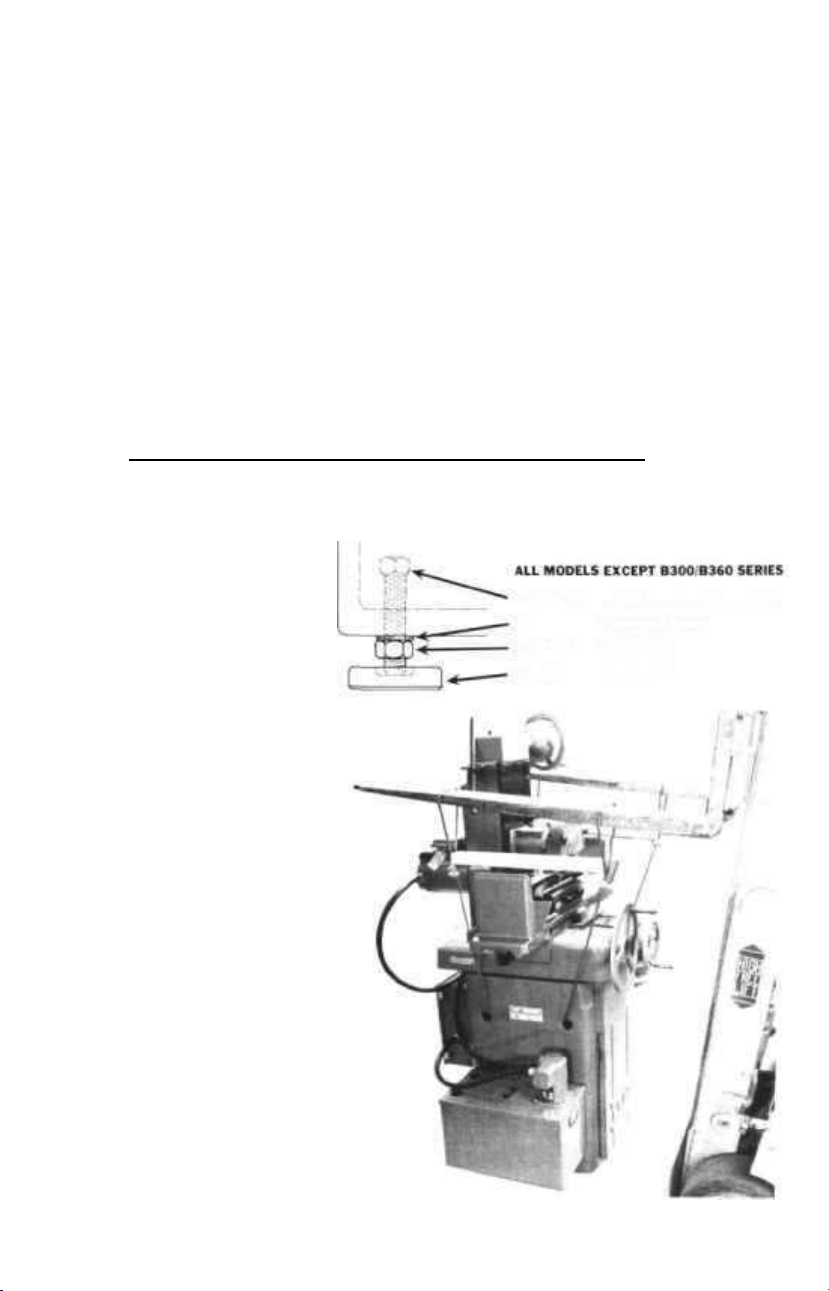
B.LEVELING:Placelevelingpadsonfloorunderneaththeboltlocationsand
lowermachinecarefully.Adjustthesetscrewsbywrenchontheirsquare
head,insideofbasecabinet,andwhenmachineislevel,lockthehexjamnut
underneaththecabinetonallfourscrews.Seediagramonpage1.Allfour
screwsmustbefirmlycontactingpadsinorderformachinetofunctionproperly.
C.B300seriesgrindershavethreeintegralbasecabinetpads.Levelingmustbe
accomplishedbyplacingmetalplatesunderoneormoreofthepads.
-1A-

Instruction Manual Section Three
PHOTO2
LUBRICATION
I.INITIAL
K.0.Leegrindersaremadewitha varietyoflubricationsystems,butthestandard
designfeaturesa self-lubricationprincipalofspoolrollersworkinginlubereservoirs
(photo2).Waysarekeptwetandcleanbymovementactionofthesaddleand
table.Checkallmachine-waysurfacesforwetnessofoilbytraversingthesaddle
andtable.Standardmachinesareshippedwithanadequatesupplyofwaylubein
thelubricationsystem,asaremachineswithone-shotorelectricallypoweredlubri-
cation.Column-waysurfaces,nut,andscrewarecoveredwithpreservativeoil.
TheB6000seriesgrindershavea built-inreservoirforlightwaylubeforthecolumn
screwandnut.
Hydraulicmachinesarenotshippedwithhydraulicoil,butbase-waysandcolumn-
waysarelubricatedbyspoolrollersorothersystems.Notethatall"V"wayends
havea nylonspringloadedplugtowipewayoilfromcorrespondingsaddleortable
"V"asshowninphotoabove.Extraway-lubeoilissentwiththemachineina
separatecontainer.
II.HYDRAULICALLYPOWEREDMACHINES
The"InstructionManual,HydraulicPartsList,CoolantPartsList"(HPL-3)which
comeswiththemachinesdiscussesset-upandmaintenanceofthehydraulicsystem.
ConsultLubeChart,page5 forremainingpointsonlubricationofhydraulicmodels.
Themainitemofconcernistokeepthelongitudinaltablewayswetwithcleanoil
—1B—

Instruction Manual Section Three
fromthehydraulicsystem.ValveNo.18picturedontheHydraulicPumpandTank
Assembly,showninPhoto5,isusedtoregulatetheflowofoilandhasbeenpro-
perlysetatthefactoryforthecorrectgradeofoilatnormaloperatingtemperature.
BALL-TRACKTABLE/SADDLEENDVIEW
PHOTOOFTOPOFBALL-TRACKSADDLE
III.BALL-TRACKHYDRAULICALLYPOWEREDMACHINESOR
MACHINESWITHPRESSURELUBRICATIONSYSTEM
Thesemodelshavespecialpipingtothecenterofthe"V"-ways,andreceive
regularamountsofoilorwaylubefromthehydraulicsystemorpowerwaylube
system.Periodicinspectionisadvisableandmaybedoneinthefollowingmanner.
Itisnecessarytodisengagethepistonrodfromthetableattherightendofthe
table.Removethethumbnut,movethetableslightlyfurthertotheright,and
removethecollarfromthepistonrod(reachunderthetableendtolocateon
rod!Movethetabletotheextremerightuntilthesaddletablewayreservoirs
—2--
A
B.

Instruction Manual Section Three
becomevisible.Theleveloflubricationshouldbemaintainedatthetopofthe
overflow,cut-outsectionofthesaddleextensioncasting.Withhydraulicma-
chines,thelevelofwaylubeisapproximately⅜"deepfromthebottom.Ifthe
levelappearstobelow,adjustoilflowvalvefortheways,(PartNo,BA931W,
IndexNo.18,page7)onhydraulictankforincreasedflowtotablereservoirs.
Similarly,attempttodetermineifpressurelubricationsystem(one-shot,auto-
maticone-shot,etc.)isputtingouttheproperamountofwaylube.Adjust
asnecessary.
SUGGESTEDINSPECTIONANDCLEANINGSCHEDULE
Monthly:
A.Waysshouldbeinspectedatleastoncepermonthifthemachineisincontinu-
oususe.
B.CleanthebottomofthehardenedTABLE"V"andflatways,atleastonceper
weekbymovingthetabletotheextremeendsofitstravel,leftandright,and
wipingthewayswitha cleancloth.
Yearly:
A.CleanoutthehollowSADDLEEXTENSIONSoneachsideofthetable.Move
thetabletooneendandthentheother,uncoveringtheseextensionareas.
Thesehollowextensionswillaccumulatesomedirtandoildrippingsfromthe
ways,andneedtobecleanedperiodically.Extensionsaredrainedbackinto
thesaddleonhydraulicmodels.
B.Removethetablefromthesaddlebyremovingthehandnut(IndexNo.3E)
fromthetablerollerhold-downtensionrodend(IndexNo.3H),underthe
saddle,bycounterclockwiseturns.Becarefultodisattachallitemsattached
tothetable,suchascoolantguardsandthehydraulicpistonrodRemovethe
tensioningspringandliftthetablestraightupwarduntilthehold-downrod
clearsthesaddlesleevehole.NOTE:Becauseofthenylontensioningplugs,
theentireassemblywillhangontothegearracksteelholddownbar(Index4,
page2).Setthetableonitssideandinspectitswaysforwear.Inspectthe
hardenedwaysandballsinthesaddleforsignsofwear.Cleanoutthesaddle
tableandballsCleanoutthesaddletablewayreservoirs.Replacewithclean
oilorwaylube,andreplacethetablebackontothesaddlebyreversingthe
stepsjusttakentoremovethetable.Tightenthehandnutofthetableroller
hold-downassemblyuntilthespringisfullycompressed,andthenloosenit
byapproximately¾ ofa turn.
IV.LUBRICATIONCHART
RefertothenumberinPhoto3,andfollowtheInstructionsandSpecificationsin
thechart.
—3—

Instruction Manual Section Three
PHOTO3
-- 4 --

Instruction. Manual Section Three
LUBRICATIONINSTRUCTIONSANDSPECIFICATIONS
Station
Numbers
1
2
3
4
5
6
7
8
9
10
27
Photo
4
12
Parts
Lubricated
Motorand
spindlebearing
deadcenter
forworkheads.
andallworkheads
withballbearings
Crossfeedand
elevatingshaft(s)
bearings
Elevatinggears
Transmission
fortable
ColumnO.D.
Columnscrew
andnut
Columnscrew
andnut
Gearrack
Gearreduction
drive
Table
SaddleWays
(Seephoto2
(Seephoto2 )
Table
SaddleWays
(SeePhoto2)
Tablesaddleways,
baseways,feed
screwandnut
Base
saddleways
(See (3)
photo2)
Motorandpump
Hydraulic
pumpmotor
Machine
Model
All
Models
B300Series
BA900,B2000,
B6000Series
Allmodels
BA903,B300,
B2000Series
B6000Series
B300.BA900,
B2000Series
B6000Series
Allmodels
Allmotorized
workheadmodels
B300,BA900.
B2000.B6000
SeriesStd.'V'
andFlatWays
BallTrack
Models
BA900B,B2000B,
B6000BSeries
Allhydraulic
models
OptionalOne-Shot
Lube— All
Models
All Standard
Models
All Hydraulic
Models
Coolant
Attachment—
AllModels
AllHydraulic
Models
When
To Oil
Every 6
Months
Check
Yearly
Yearly
Monthly
Every6
Monthsto
1Year
Yearly
Monthly
Check
Yearly
Every1 to
6months
depending
onusage
Monthly
Check
Every6
Months
Sec
Instruction
onMachine
Every6
Months
to
1Year
Procedure
None
Servicebyremovingrearplateorthru
frontcabinetdoor—Cleanandrepack,
Servicebyentrythrufrontcabinetdoor.
Removefillerplugscrewandfillto½"
fromtop.
Slipdowncolumnboot,wipeO.D.with
oiledcloth,
Fillthroughoilcuponcolumnhousing.
Removegrindinghead;removecolumn
cap,brushscrewwithlube.
Columnhasbuilt-inreservoirwithwick.
Fillthrucenterhexholeinpivotstud
underdovetailslide—½pintcapacity.
Brushclean,oilbymovingtabletoex-
tremes— eitherdirection.
Fillthroughscrewpluguptobottom
offillerhole.
Waysarerollerlubricated.Remove
table,cleanreservoirs,fillwithlube.
Feelways:theymustrunwet.
Seepage3.Illfortableremoval.
Nowayluberequired.Waysareself-
lubricatedfromhydraulicsystem,See
pageIB.II.
Pullplungeraspermachineinstruction.
Electricunits— selftimed-
Movetabletoextremerightandleft
exposingoilreservoirtubesinsaddle.
Pouroilintotubes(see(5)photo2)
untiloilrunsfromeitherendofV-
ways.OnB900Seriesmovesaddleto
extremeoutwardposition,fillreservoir
throughtubes:returnsaddletoextreme
inwardposition;repeatfillingprocedure.
NOTE:Ifbasewaysareverydirty,re-
movesaddlebyremovingboltsholding
saddlefeedbar(fromunderneathbase
top),thatholdsthebronzecrossfeed
nutinposition.Slidesaddlefront:re-
move.Cleanchannelways:fillto
bottomof"V";keepnylonplugsin
wayends.
None
Checkmotor,addoilasdirected,or
yearly.
Lubricant
Specification
Factorygrease-packed
forlifeofbearings
Crease,calciumbase
340viscosity
Factorysealedwith
600WCylinderOil
Lightwaylube
Lightwaylube
Lightwaylube
Clinginggrease
orwaylube
600W
cylinderoil
Lightclinging
waylube
2671Extra
LightWay
LubeOnly
Hydraulicoil
Lightclinging
waylube
Lightwaylube
Eachwayholds
approximately1 pint
Factory
grease-sealed
MotorOil,
S.A.E.No.10
--5-

Instruction Manual Section Four
MODELB6062HWITHB10043MMOTORIZEDWORKHEAD
PHOTO4
1.
2.
3.
4.
5.
6.
7.
8.
9
10.
1!.
12.
13.
SwitchonMachinewithToggleSwitches
BeltGuard
TiltingDegreeDial
CartridgeSpindleLackingScrew
WetWheelGuard
B923CLMotorShaftGuard
GuardMountingBracket
SwivelSocketScrews
TailstockLockingScrew
RearColumnLockScrew
Hex Nut
SwivelLockingNut
DovetailSlide
14.
16.
18.
19.
20.
21.
22.
23,
24.
25.
26.
27.
TableIndexPlate
TableAdjustmentScrews
AdjustableStop
TableStop
CrossfeedHandwheel
ThumbNut
ElevationHandwheel
KnurledKnobtoEngageDrive
TableTraverseHandwheel
ElectricalControlBox
MovableIndexDisc
On-OffCoolantSwitchifspecifiedon
CoolantTank
-- 6 --

Instruction Manual Section Four
—7—
MODELB2060H
PHOTO5
1.On-OffValveControl
2.SpeedCentral
3.DirectionalControlArm
4.DwellControl
5.TableStops
6.Hyd.CylinderThumbNut
7.RodDriveCollar
8.SwivelTableAdj.Screw
9.ClampBarSocketScrews
10.IndexPlate
11.Pointer
12.FrictionSocketScrews
13.HexSocketScrew
14.SpringCenterTailstock
15.ThreadedPlunger
16.TailstockLever
17.TailstockCenter
18.OilFlowValveforWays
removecoverforadj.
20.SwivelTable
21.TailstockLockingScrew
22.B943MotorizedHead
23.ElevationHandwheel
24.06183LightFixture

Instruction Manual Section Four
GENERALOPERATIONINSTRUCTIONS
I.SAFETYPRECAUTIONS
A.ALWAYSWEARSAFETYCLASSESoraneyeshieldwhenoperatinga grind-
ingmachine.
BALWAYSUSEA WHEELGUARDANDBELTGUARD.Machinesarepro-
videdwithwheelguardsofthecorrectsizeandnecessarymountingbrackets.
ConsultPartIIIofthissectionandgeneralset-upphotosinthismanualon
howtoattachthesetothemachines.
C.MountingWheels
1.CheckwheelR.P.M.chartsonthemachineorPartIII,pages14,15ofthis
sectionforthecorrectormaximumsafespeedforthesizeandtypeof
wheelbeingused.Donotexceedthisspeedorthespeedmarkedonthe
wheeloritsblotter.TheR.P.M.listedisthemaximumsafespeedfora
givennewwheeldiameter.
2.Inspectallgrindingwheelspriortomounting.Usethefollowingcheckfor
cracksofvitrifiedbondwheels:Holdthewheelbya smallshaftthrough
itshole,andthentaptheedgewitha non-metallicobject.Anundamaged
wheelwillsounda clearmetallicring.Checkresinoidbondwheelsand
othertypesofwheelbondsbyvisualinspection.
3.Neveraltertheholeinthewheelorforcethewheelonthespindle.
4.Useoneclean,smoothblotteroneachsideofthewheelundereachflange.
5.Tightenthearbornutonlyenoughtoholdthewheelfirmly.
6.Standbackandoutofplaneofthewheelwhenfirststartingthegrinding
spindle(WHEELHEADMOTOR).Allowthemotortooperateforabout
aminutepriortogrinding.
7.Specialcautionisneededwhengrindingonthesideofthewheel.Wheels
withflatsidesmayhavesufficientside"run-out"tonecessitatetruingthe
sidewitha dressingstick.A slightlyhollowrecesstowithin1/16inchofthe
peripheryofthewheelisrecommendedtolimittheamountofsidethrust
onthewheel.Usesaucerwheelswheneverpossibleforsidegrinding.
8.Storewheelsina safeplace(FREEFROMEXTREMESOFHUMIDITY
ANDTEMPERATURE)nearthegrindingmachine.
9.SeePartIIinthissectionforproceduresonmounting,truing,anddress-
ingwheels.NOTE:Wheelarborclampingflangesmustbethesamediam-
eterinsideandoutside.ThewheelcolletorarborO.D.shouldvarywith
thewheeldiameter.Safetycodesrecommenda diameterequaltonotless
than⅜ ofthediameterofthewheel.
D.Werecommenda dustcollectsystemforusewithdrygrinding.
E.Rings,wristwatches,orlooselong-sleevedshirtsarehazardousitemstowear
duringgrindingoperations,
II.ELECTRICALCONTROLS
Beforestartingmachine,learnthelocationandfunctionofeachelectricalswitch.
(REFERTONUMBEREDPOSITIONSINPHOTO4.)
A.WheelheadandSpindleMotor:Machineswithstandardtoggleswitcheshave
theswitchlocatedatpoint(1).Thisswitch,locatedonthetopofthemotor
- 8 -

Instruction Manual Section Four
housing,isa "Forward-Off-Reversing"typewiththe"Offpositioninthecen-
ter.Spindlemotorsshouldbecompletelystoppedinonedirectionpriorto
reversing.Checktherotationofthespindlefor"Forward"switchdesigna-
tion,Rotationshouldbedownatthepointofgrindingasonefacesthewheel
periphery,withthespindleparalleltothegrindertable.Somemachineshave
astandardpushbuttonboxonthesideofthemachineat(25)withthree
positions,"Start-Stop-Reverse."Thefunctionofanyotherswitchesatthis
pointisdescribedonthestationbox.Specialelectricalcontrolsconsistingof
pushbuttonandothertypesofswitchingarelocatedatposition(25).
B.MotorizedWorkheads:Unitswithtoggleswitcheshavetheswitchlocatedat
topofunitandtheseare"Forward-Off-Reverse"switches.WARNING:Prior
toturningontheworkheadmotor,makesurethespindleisfreetoturn-—that
thespindlelockisloose.Workheadsmayplugintothemachineorhavea
separatewallplug.Somemotorizedworkheadsthatplugintothemachine
electricalpanelhave"Forward-Off-Reverse"switchesatposition(25).
C.HydraulicMachines:Thesemachineshave"On-Off"switches,toggleorother
typelocatedat(25).WARNING:Priortoswitchingonhydraulicmotors,
checkthehydraulictankforadequateoilandmakesurevalvesareinthe"off"
positionSeethespecialinstructionsontheoperationofhydraulicgrinders,
PartIII,A-2ofthissection.
D.CoolantSystems:Coolantpumpsmayhave"On-Off"switchesatposition(25)
oratthepumpunititselfat(27).Coolantsystemsplugintothemachine
electricalpanelorhaveseparateplugsforwallconnection.
E.SpecialElectricalControls:Somemachineshavespecialstartingmotorcontrols
whichmayfeatureothertypesofswitchesthanthestandardtoggleswitch.
Machinesmayhave"overload-under-voltage"magneticstarterslocatedapart
fromthemotororitsusualswitchlocation.Othermachineswillhavemag-
neticstartersforeachmotorlocatedina I.I.C.oiltightjunctionboxatthe
rearofthemachine.Thesesystemsmayormaynotfeaturepowertrans-
formersforlowervoltagestartercircuits.Withthesecontrols,specialswitches
arelocatedat(25)forstartingandstoppingmotors.
III.MACHINEOPERATION
A.(REFERTOPHOTOS1,4,5,6 and7)TableTraverse:Thismaincontrolis
locatedatposition(24)Photo4 onmostmachinesandconsistsofa two-speed
transmissionandhandwheel.Somemachinemodelsalsofeatureoneormore
rear-operated,singlespeedtablecontrolsconsistingofhandwheelandfriction
lock-inorlock-outshaftandpinion.TheB6060andB6062seriesgrinders
havea swinghandleadjustment,whileallothermodelshavefriction-slide
extendinghandles.
1.Toeffectmanualtabletraverse,engagethetransmissionasfollows:
(a)B300Series—Thetransmissionisshippedwithgearsinneutral
position.Toengagedirectdrive,turnandpushinthehandwheel
(24)Photo4 untilspringloadedballisfeltdroppingintoa grooveon
thetransmissionshaft.Toshifttolowratio,pullthehandwheelout.
Astheshaftandhandwheelmoveoutoftheneutralgroove,thelow
ratiogroovewillbefelt.Handwheel,shaft,andpinionarepositioned
relativetothegearrackbytheballridingina grooveontheshaft.
—9-

Instruction Manual Section Four
1.B855YSpecialNut
2.5/16x 3/4NFHexSocketCapScrew
3.B860CNSpecialNut
4.BeltAdjustmentHandwheel
5.V-Belt
6.EccentricShaftHandNut
7.ColumnLockLever
3.B955CLockScrewAssembly
PHOTO7
(b)AllOtherModels:Thetransmissionisshippedwithgearsinneutral
position.Thepiniongearisofftherack.Toengagethedirectdrive
ratio,turnandpulltheknurledknob(23)Photo4 tostartthepinion
ontotherack.Continuetopullwhileoscillatingthehandwheel
untilaninnerkeyisfeltdroppingintothedirectdriveslot.Toen-
gagethelowratio,continuepullingtheknobwhileoscillatingthe
—10--
This manual suits for next models
9
Table of contents