8 Service Manual MW 800.0
For internal use only
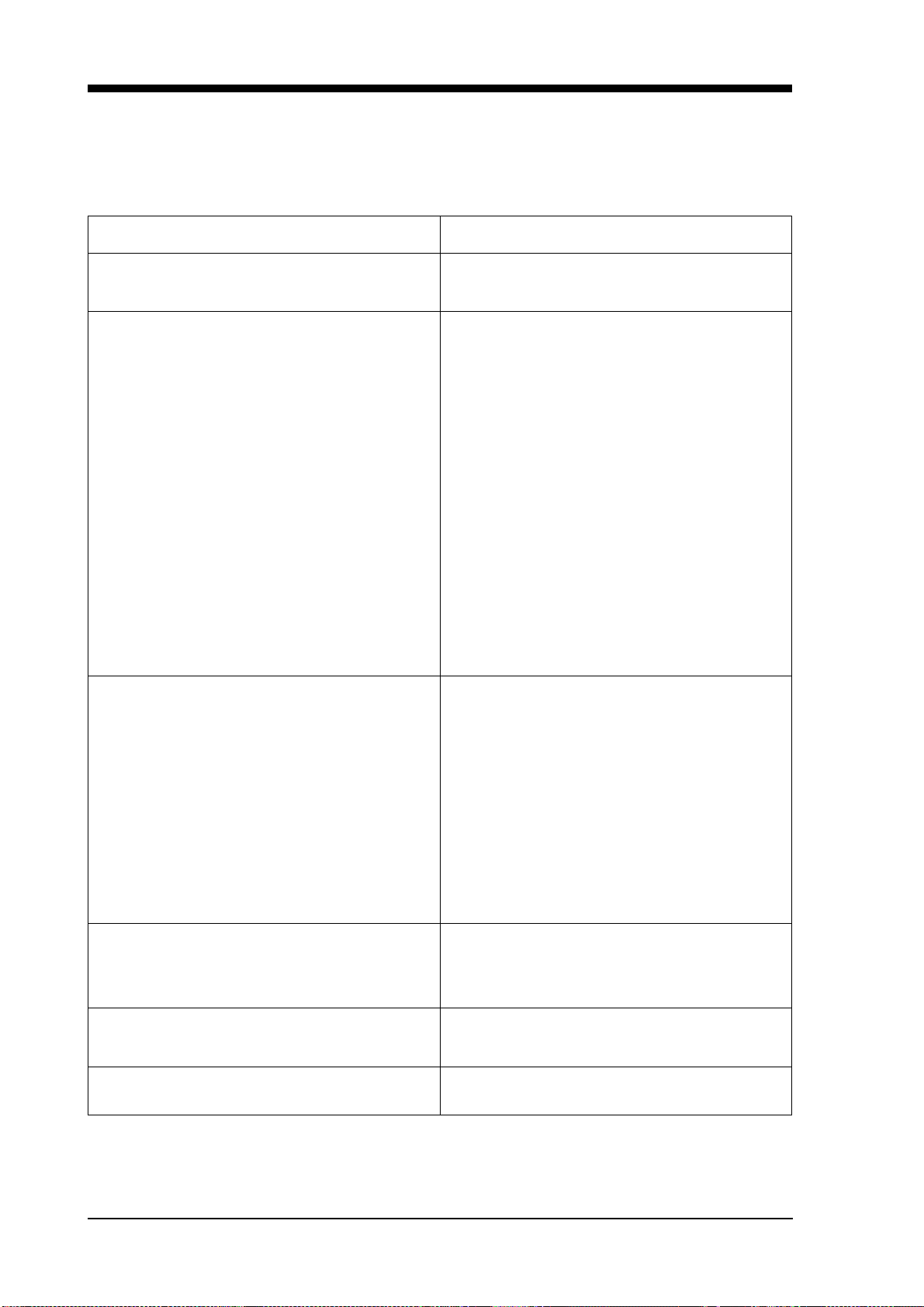
3. Trouble shooting guide
3.1 Trouble shooting table
Problem Points to check
Cavity lamp does not light, but other electrical
components (e.g. turntable) are working. 1. Lamp burnt.
2. Bad contact between lamp and lamp socket.
Cavity lamp does not light, all other electrical
components also do not work. 1. Power outlet has no contact to the socket.
No electric supply.
2. Fuse blown.
3. Faulty contact between fuse and fuse
holder/clip.
4. Loose door hinge, door not set properly,
adjustment of locking not correct; this leads
to blowing of the fuse.
5. Faulty connection UL-switch.
6. Short-circuit in electric circuit. Filament of
lamp blown, short-circuit of high-voltage
capacitor; this leads to blowing of fuse.
7. Faulty contact of contacts or connectors of
control element, or primary or secundary
interlock switch.
8. Defective high-voltage diode .
The microwave seems to function but the food
stays cold. 1. Defective magnetron (defective thread,
thread short-circuited to earth, etc).
2. Earth conductor of high-voltage transformer
defective.
3. Filament short-circuited to earth.
4. Damaged filament.
5. Faulty contact at magnetron connectors.
6. Defective control units.
7. Damaged high-voltage diode, a humming
sound occurs.
Microwave runs for a short period of time, but then
stops. 1. Blocked cooling fan.
2. Open cooling fan motor circuit.
3. Defective cooling fan control relay.
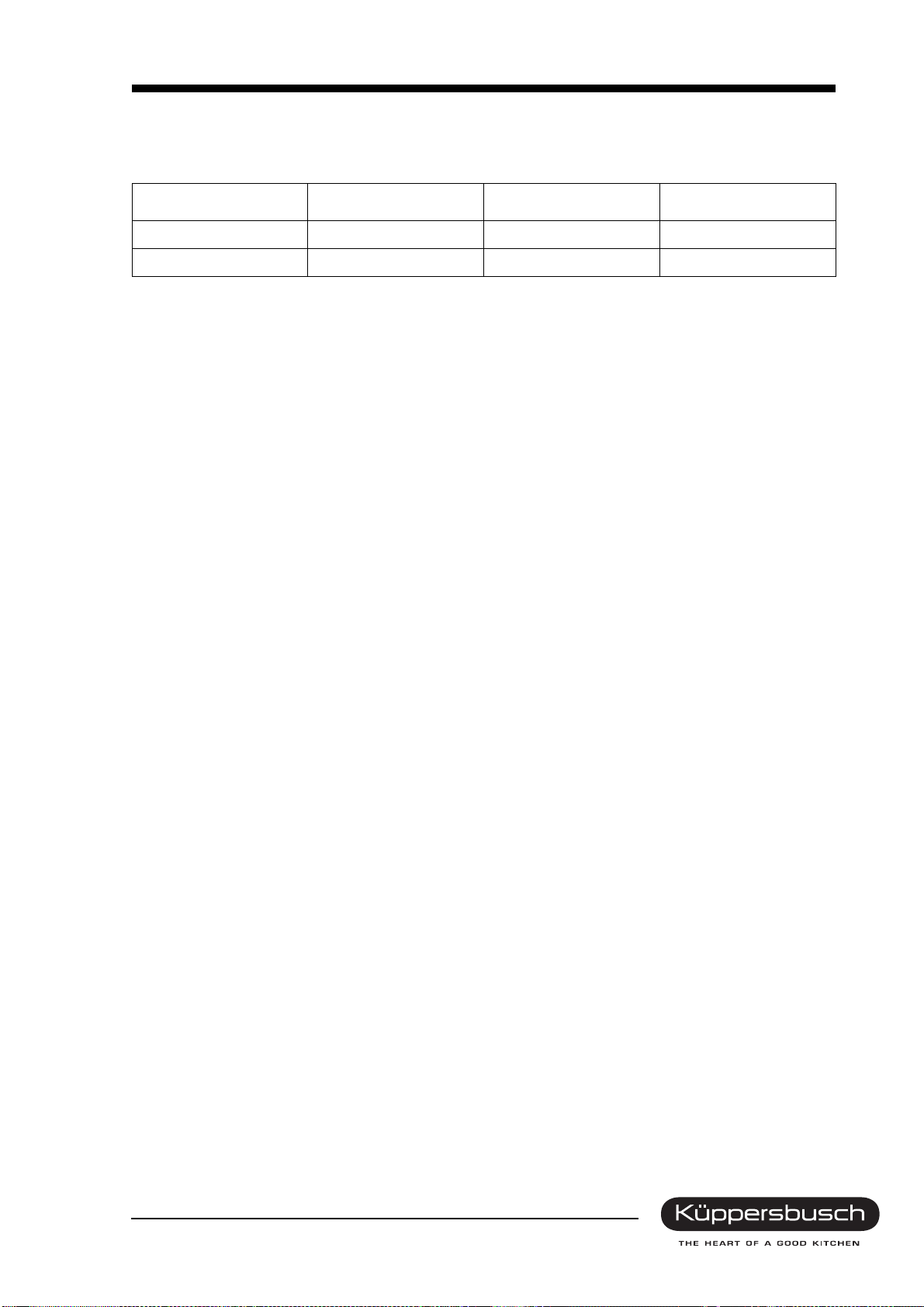
Turntable does not turn. 1. Defective turntable motor.
2. Deformed turntable shaft.
Circuit breaker is activated. 1. Strong leakage of electrical components
(mostly motor).


 Operating and installation instructions")