KABTRONICS World Clock Product guide
World Clock
Operating and
Assembly Manual

KABTRONICS
World Clock Kit Page 2
Table of Contents
INTRODUCTION ..................................................................................................3
UNPACKING/PARTS LIST ..................................................................................4
SOLDERING ........................................................................................................5
ASSEMBLY INSTRUCTIONS – DISPLAY SLICE ...............................................7
ASSEMBLY INSTRUCTIONS – CONTROLLER SLICE....................................13
OPERATING THE WORLD CLOCK ..................................................................18
PARTS IDENTIFICATION ..................................................................................23
THEORY OF OPERATION.................................................................................29
IN CASE OF DIFFICULTY .................................................................................30
SPECIFICATIONS..............................................................................................31
CIRCUIT BOARD VIEWS...................................................................................32
SCHEMATIC ......................................................................................................33
Copyright © May 9 2010 by KABtronics
Document version 1.01 for use with PC board version 2

KABTRONICS
UNPACKING/PARTS LIST
World Clock Kit Page 3
Introduction
This is a kit to build a clock displaying time for multiple locations.
This clock is made of slices, one controller slice, and multiple display slices.
This manual first guides the assembly of the slices, followed by operating the clock. There is a
section describing the parts if you are unfamiliar with electronic parts, and a section describing the
underlying design of the clock.
You need to make 670 good solder joints to complete a display slice and 719 for the
controller slice.
KABTRONICS
UNPACKING/PARTS LIST
World Clock Kit Page 4
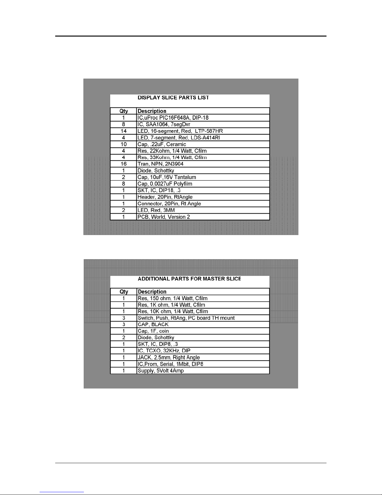
Unpacking/Parts List
Gently unpack the contents of the box. You should find one display pack for each display,
and one controller pack if you are building a controller.
KABTRONICS SOLDERING
World Clock Kit Page 5
Soldering
This manual can’t teach the art of soldering, but here are the basics. Remember, you need to
make over 670 GOOD solder joints for each slice; each bad joint will be an adventure in
troubleshooting.
Wet the tip of the iron with a bit of solder and wipe off the excess solder on the wet sponge
occasionally, or when you notice the joint is not heating properly. The small amount of solder left
on the tip helps conduct heat to the lead and the pad.
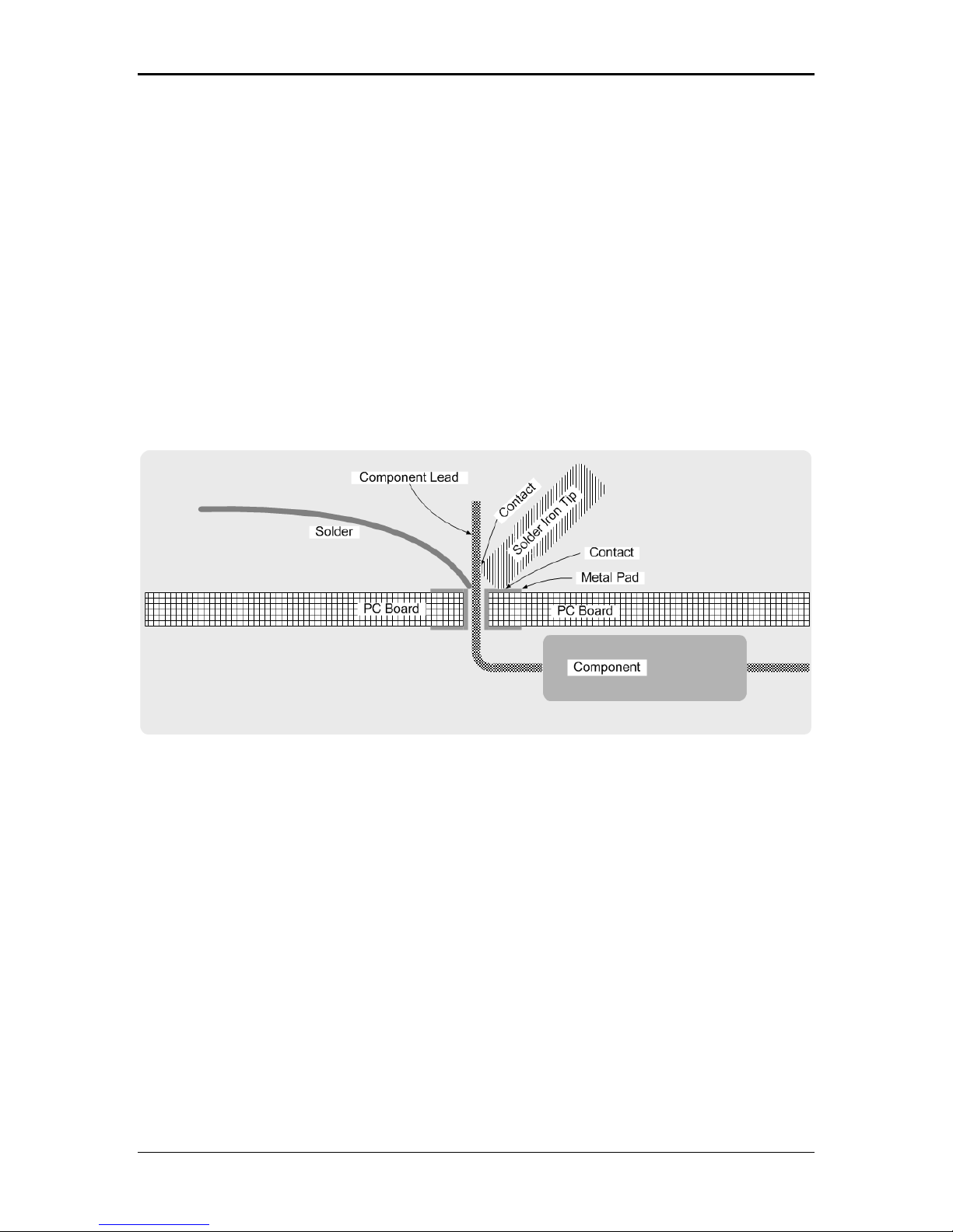
Insert the component leads and press the component flat against the PC Board. Slightly spread
the leads to hold it in place when you flip the board over to expose the back side with the
component lead facing up.
•Make good contact between the iron, the lead, and the pad on the board so the lead and
the pad both heat up enough to melt the solder.
•It should take from 0.5 to 1 second for the joint to become hot enough to melt the
solder.
•Don’t overheat the joint, as soon as the solder melts and wicks into the joint remove the
iron and hold still for a few seconds until the joint freezes.
KABTRONICS SOLDERING
World Clock Kit Page 6
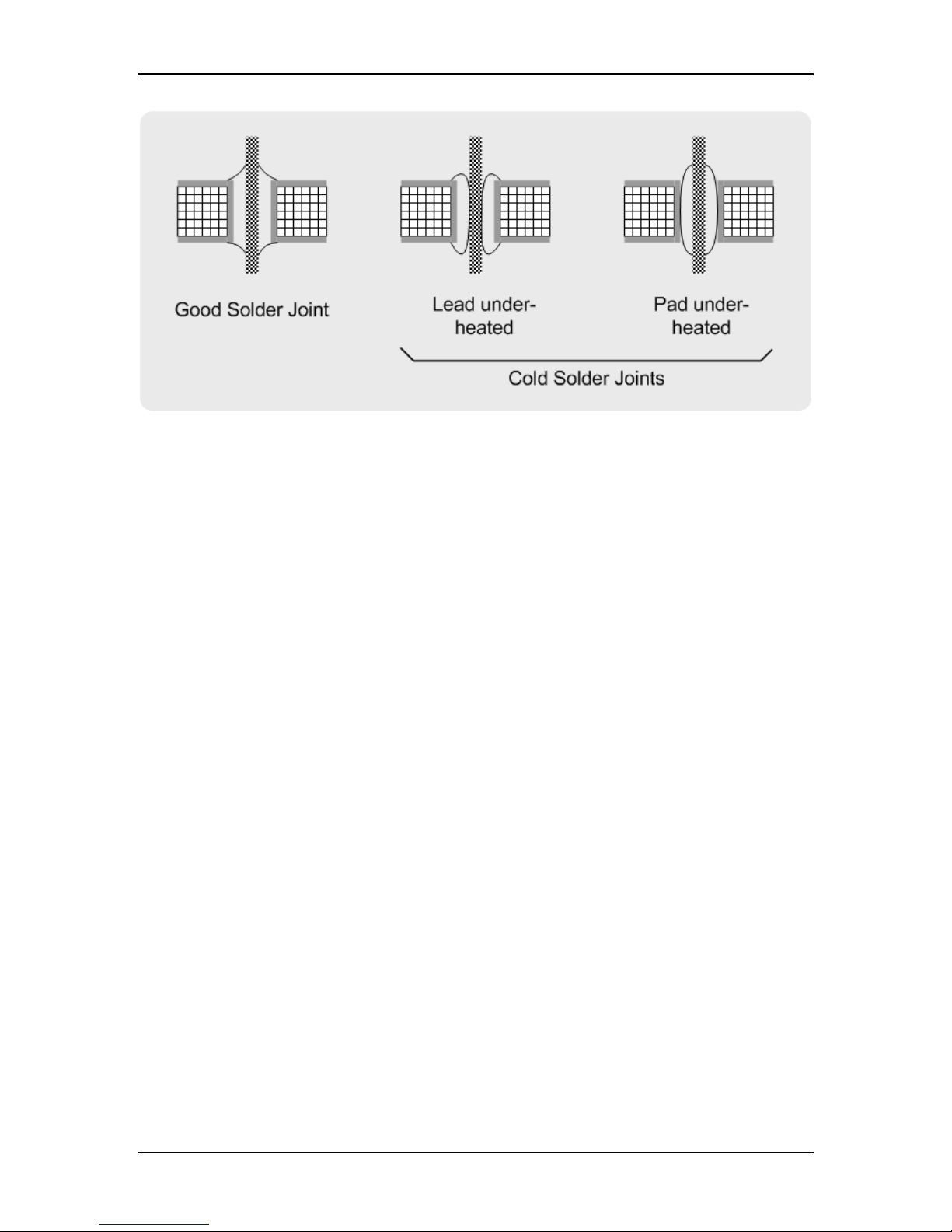
A good solder joint will form a shiny curved surface bonding the lead and the pad on the PC
board. If the lead wasn’t heated enough to melt the solder, the solder will wick in to the pad, but
will not adhere to the lead. You may notice a dark line around the lead where the solder dives
down through the hole.
A similar bad joint forms when the pad wasn’t heated enough to melt the solder. A cold solder
joint can often be fixed by reheating the joint; sometime a little more solder will be needed.
More detailed instructions can be found on the internet with a little searching on the topic of
soldering.
After inspecting the solder joint, clip off the excess lead using the diagonal cutter. Cut at the top
of the solder joint; don’t dig into the solder joint.
Unsoldering
A supply of de-soldering braid is supplied with the kit. If you find the need to remove a
component, use the de-solder braid by pulling out a few inches and pressing the braid against the
lead and the pad using the iron. You will see the solder melt and spread into the wick leaving very
little solder left in the pad.
Sometimes it helps to clip the lead off the component so you can deal with each lead separately.
Optional Clean-up
The clear sticky rosin left around the solder site can be cleaned up with alcohol and a toothbrush,
but be sure to let the board dry before expecting the board to operate properly. You won’t hurt
the circuit by powering it up, but it won’t count right until the board has completely dried. Water
soluble rosin-cored solder is available at hobby stores. As for me, I don’t bother to clean up the
board unless the counters are not working right, then I clean off the rosin.

KABTRONICS ASSEMBLY INSTRUCTIONS
World Clock Kit Page 7
Assembly Instructions – Display Slice
You will need the following tools to build your clock.
•Soldering Iron meant for electrical work
•Small Diagonal Wire Cutter
Instructions for building a display slice are first. The additional instructions for building the
controller slice follow.
One side of the PC board has white paint markings, shapes, and reference designators. That
marked side is the component side, upon which all the components will be placed.
( ) Load the four 22K and four 33K resistors located
on the lower edge of the board. Push the part flush
onto the board, spread the leads slightly and solder.

KABTRONICS ASSEMBLY INSTRUCTIONS
World Clock Kit Page 8
Clip the leads off just above the solder joint; don’t dig into the solder joint. Soldering and clipping
won’t be mentioned again, you need to do it for each part as you load it.
( ) load the diode into the space marked D1, be sure to line up the white line on the diode with
the white line on the board.
( ) load the eight 24 pin SAA1064 ICs. The notch on IC should match the notch on the board.
( ) load the 18 pin socket at location U1, match the mark on the board with the mark on the
socket.

KABTRONICS ASSEMBLY INSTRUCTIONS
World Clock Kit Page 9
The capacitor locations are indicated by symbols shown in the table.
( ) load the eight 0.0027 capacitors
( ) load the ten 0.22 capacitors
Don’t load the 10uF capacitors yet, they are loaded after the displays.
The four 7 digit displays have two decimal points, these decimal points can be used to orient the
display; the decimal points go towards the bottom.
Hold the display flat against the board as you solder. These displays are very sensitive to
overheating so be quick about soldering these pins.
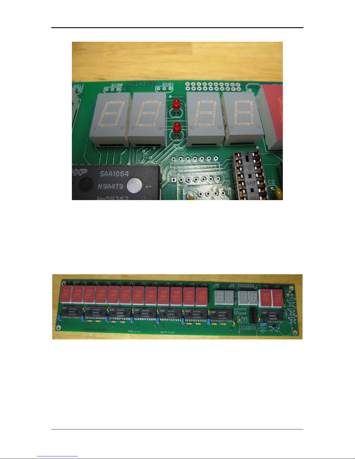
KABTRONICS ASSEMBLY INSTRUCTIONS
World Clock Kit Page 10
( ) load the two red LEDs between the displays as shown above.
The shorter lead goes in the hole near the flat part of the outline, closer to the bottom edge. Try
to have the top of the LED even with the height of the display.
( ) load the 14 alphanumeric displays one at a time. These also have a decimal point that should
go toward the lower edge. Push these against the board while you solder the leads, and be careful
again about over heating the leads.
( ) load the 16 transistors as shown below.
Table of contents
Other KABTRONICS Clock manuals

Popular Clock manuals by other brands

Silicon Laboratories
Silicon Laboratories SI5324 manual

Heathkit
Heathkit GC-1005 Assembly manual

Oregon Scientific
Oregon Scientific PRYSMA RMR221P manual

Andrew O'Malley
Andrew O'Malley DOTKLOK Assembly instructions

ALGE-Timing
ALGE-Timing ASC3 manual

Bodet
Bodet Profil 960 Installation and operating instructions


Progetti
Progetti KALIMERO Directions

La Crosse Technology
La Crosse Technology WT-3141b Quick setup instructions

La Crosse Technology
La Crosse Technology W86531 owner's manual

Sharp
Sharp SPC900 instruction manual

La Crosse Technology
La Crosse Technology 404-50447 quick start guide

Datexx
Datexx DF0063 quick guide