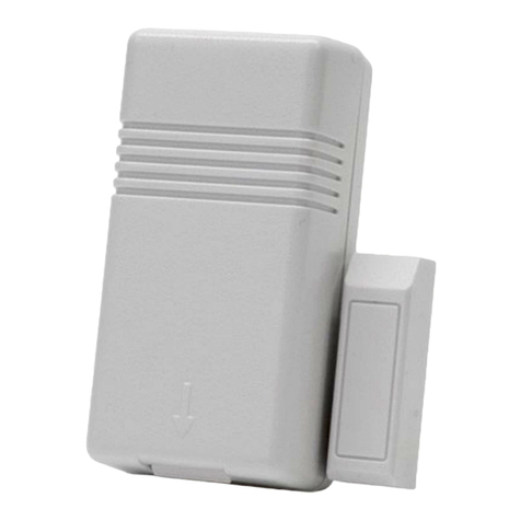
Kadtronix Smart Temperature Relay Switch User manual

Rev. 2 (11/18)
Smart Temperature Relay Switch (STRS)
User Manual
Kenneth Delahoussaye Consulting
web: www. adtronix.com
email: adtronix@att.net
Copyright © 2018
All rights reserved
1

Table of Contents
1 - Introduction...................................................................................................................4
1.1 - Features..................................................................................................................5
1.2 - Trigger Activation..................................................................................................6
2 - Setup.............................................................................................................................7
3 - Wireless Sensors...........................................................................................................
4 - Wired Switches.............................................................................................................9
5 - TB-1 Wiring Connections...........................................................................................10
6 - Windows Host Software..............................................................................................11
6.1.1 - Device List...................................................................................................12
6.1.2 - Temperature Units........................................................................................16
6.1.3 - Color-Coded Aging.......................................................................................16
6.1.4 - Sensor Messages...........................................................................................16
6.1.5 - Application Status.........................................................................................17
6.2 - Settings................................................................................................................1
6.2.1 - Serial Com Port............................................................................................1
6.2.2 - Message Aging.............................................................................................19
6.3 - Controller Setup...................................................................................................20
6.3.1 - Audio / Visual...............................................................................................21
6.3.2 - Wired Switch Inputs.....................................................................................22
6.3.3 - Trigger Settings............................................................................................23
6.4 - Sensor Properties.................................................................................................26
6.4.1 - Sensor Description........................................................................................2
6.4.2 - Trigger Limits...............................................................................................29
6.4.3 - Sensor List....................................................................................................34
6.5 - Forced Relay Activation......................................................................................35
6.6 - Enable Audible Alerts..........................................................................................36
6.7 - Enable Data Logging...........................................................................................36
6. - Log Preexisting Triggers......................................................................................37
2

6.9 - View Data Logs...................................................................................................3
7 - ASCII Commands.......................................................................................................40
7.1 - Settings................................................................................................................42
7.1.1 - Assign General Settings................................................................................42
7.1.2 - Retrieve General Settings.............................................................................44
7.1.3 - Assign RF Sensor Settings............................................................................45
7.1.4 - Retrieve RF Sensor Settings.........................................................................46
7.1.5 - Restore Default Settings...............................................................................46
7.2 - Peripheral Activation...........................................................................................47
7.2.1 - Activate Relay..............................................................................................47
7.2.2 - Activate Beeper............................................................................................47
7.3 - Miscellaneous Commands...................................................................................4
7.3.1 - Clear Sensor States.......................................................................................4
7.3.2 - Get Firmware Version...................................................................................49
7.3.3 - RF Signal Test..............................................................................................49
- ASCII Data Messages.................................................................................................50
.1.1 - Format..........................................................................................................50
.1.2 - Decoding......................................................................................................51
.1.2.1 Trigger / Relay Status.........................................................................................51
.1.2.2 Measurement Data..............................................................................................52
.1.2.3 Trigger Processing Indicator...............................................................................54
.1.2.4 High Temperature Limit.....................................................................................54
.1.2.5 Low Temperature Limit......................................................................................54
.1.2.6 High Relative Humidity Limit............................................................................55
.1.2.7 Low Relative Humidity Limit............................................................................55
.1.2. Sum.....................................................................................................................56
9 - Care and Maintenance.................................................................................................57
10 - Warranty.................................................................................................................... 5
11 - Contact Information..................................................................................................59
3

1 - Introduction
The Smart Temperature Relay Switch (STRS) provides switched control of user
equipment based on specified trigger criteria. Useful in a vast array of applications, the
STRS is designed to provide many years of reliable operation.
Companion Windows application software permits configuration of a variety of settings
including trigger limits (temperature and/or relative humidity). The STRS communicates
with the host PC via a USB-to-RS232 adapter cable (included). Once configuration is
complete, the Windows application is no longer needed (unless logging is desired).
The STRS accepts wireless (RF) sensors as well as optional wired peripherals such as
temperature-activated switches. (Virtually any non-voltage switch may be an acceptable
wired input.) The system is expandable up to four (4) wireless sensors and four (4) wired
switches.
The STRS is ideally suited for any application where it may be necessary to evoke an
action based on changes in temperature and/or relative humidity such as the following:
•Exhaust systems
•Farming & agriculture
•Climate control
•Greenhouse monitoring
•Environmental control
•Industrial automation
•Plant & produce cultivation
•Freezer alarms & refrigeration systems
4

1.1 - Features
The STRS provides an array of viable features and options:
•Configurable settings including setpoint triggers for temperature and/or relative
humidity
•Four (4) LED indicators show trigger status:
•Trigger-pending = solid red
•Trigger-active = flashing red
•Available low-cost RF sensors for remote temperature/humidity monitoring.
Applicable temperature range listed below (Celsuis and Farenheit).
•-40 deg.C to 70 deg.C
•-40 deg.F to 15 deg.F
Note: Accurate to +/- 2 deg.F
•Applicable humidity range listed below:
•1% to 99%
Note: Accurate to +/- 3%, +/- 5%
•Four (4) wired inputs for optional wired switches, thermostats, etc.
•Expandable up to four (4) RF sensors and four (4) wired switches
•Onboard Form-C relay (contact ratings: 10A @ 125VAC, 6A @ 277VAC, 5A @
30VDC)
•Windows host monitoring via USB (adapter cable included)
•DB-9F (female) connector
5

1.2 - Trigger Activation
The STRS utilizes compatible wireless sensors for transmitting temperature and relative
humidity measurements. You may define trigger limits values relevant to these
measurements. For each desired sensor, a unique set of high and low limits can be
configured.
Note: Limits may be defined for tem erature and/or relative humidity.
A trigger activation occurs when a defined temperature or humidity trigger limit is
breached. The violation can result in relay activation and/or piezo (beeper) annunciation,
depending on your prescribed trigger settings.
Note: O tional wired switches may also be utilized to generate trigger activations.
6

2 - Setup
Setup primarily involves the following operations:
•Install USB drivers (using the CD included with the adapter cable)
•Install STRS host application software (using download file “strs_setup.zip”).
•Connect the USB adapter cable (DB-9 end to STRS controller and USB end to
the host PC)
•Connect the AC power adapter (barrel plug end to STRS controller and opposite
end to a 110vac outlet).
Additional setup & installation details are provided in subsequent sections of this manual.
7

3 - Wireless Sensors
The following Acurite wireless (RF) devices are compatible:
•6002M - Temperature + humidity, indoor/outdoor, a.k.a, 6002RM, 592TXR
•6044M - Temperature + humidity, indoor only, featuring LCD display
•6053M - Range extender/repeater, indoor/outdoor
Follow the instructions included with your Acurite device for installation instructions and
operational details.
Notes:
•Acurite sensors ty ically include a channel select switch (A, B, or C). The STRS
laces no de endence on this setting. Therefore, you may choose any desired
channel.

4 - Wired Switches
WARNING: Be sure that ower is disconnected until all wiring has been com leted and
verified.
The STRS controller accepts four optional wired peripherals such as push-button
switches, temperature-activated switches, thermostats, etc. (Virtually any non-voltage
switch may be applied to a wired input.) To apply your switch device to a wired input,
perform the following operations:
•Disconnect the STRS power source.
•Detach cover by removing the retaining screws.
•Locate the 14-position wiring terminal connector. (Refer to TB-1 Wiring
Connections.)
•Attach wires as necessary, being careful to utilize the proper wire slots. (Each
switch has a designated input terminal and a return.)
•Replace the cover and secure with retaining screws.
•Restore power to the STRS controller.
Note: Wired switch in ut(s) must be a ro riately configured and enabled.
9

5 - TB-1 Wiring Connections
The STRS controller provides a 14-position wiring block with the following screw
terminal connections.
Terminal Description
1 +12VDC in/out
2 Ground
3 Reset (active-low)
4 Wired switch / thermostat #1
5 Wired switch / thermostat #2
6 Wired switch / thermostat #3
7 Wired switch / thermostat #4
Switch return #1
9 Switch return #2
10 Switch return #3
11 Switch return #4
12 Relay contact - COM
13 Relay contact - N/C
14 Relay contact - N/O
Notes:
•Only a subset of the above connections will be required in a given a lication.
•If su lying your own ower source at terminals 1 & 2, do not also concurrently
rovide ower with the ac ada ter at the barrel connector.
10

6 - Windows Host Software
Available STRS host software for Windows provides functionality for configuring trigger
parameters as well as performing realtime monitoring. The following is a summary list of
software features
•Establish trigger parameters
•Monitor sensor measurement
These are the requirements for installing the host software on your PC or laptop
computer:
•Pentium or compatible CPU
• MB RAM
•1 MB available hard disk space
•1 available RS-232 or USB port
•Windows XP or higher
11

6.1.1 - evice List
The device list shows a collection of detected sensor devices and their operating
parameters.
Use the horizontal scroll bar to display additional data columns.
Each row corresponds to a particular sensor, while each column shows a specific detail or
data parameter as listed below:
•Addr – numeric sensor address, displayed in hexadecimal format.
•Desc – user-specified description and/or location for the sensor.
•ID – device identifier (specified by the sensor manufacturer).
•Ch – channel code (selectable at the sensor).
•Batt – battery staus (“ok” / “low”).
12

•Temp – temperature (reported in degrees Fahrenheit or degrees Celsius, depending
on the selected temperature units).
Notes:
•Trigger-activated tem erature data will be indicated by a flashing (blinking)
measurement reading.
•The a lication rovides an automatic trending feature. When a trend is
detected, the a ro riate indicator is shown to the right of the
measurement:
•> - indicates u ward (increasing) trend
•< - indicates downward (decreasing) trend
•RH – relative humidity, a reading that occurs in the range of 0 to 100%.
•Trigger-activated relative humidity data will be indicated by a flashing
(blinking) measurement reading.
•The a lication rovides an automatic trending feature. When a trend is
detected, the a ro riate indicator is shown to the right of the
measurement:
•> - indicates u ward (increasing) trend
•< - indicates downward (decreasing) trend
•Trig'd – reports whether the temperature and/or humidity measurement(s) have
resulted in a trigger event (i.e., relay activation). One of the following indicators
will be shown:
•“T” - the temperature has reached a high or low limit threshold, resulting in a
trigger-ready condition (see note).
•“RH” - the relative-humidity has reached a high or low limit threshold,
resulting in a trigger-ready condition (see note).
•None - the field is blank or empty when there is no trigger activation.
Note: A trigger-ready measurement is indicated by a reading that is shown
flashing (blinking). Trigger-activation occurs when the following conditions
are met for a trigger-ready measurement:
•Pre-trigger delay has ela sed, if a licable
•Trigger activation is not already in rogress (by another sensor)
13

•Activity – numeric counter that increments for every data message received from
the sensor.
Note: Activity counters are derived by the Windows host a lication. They are not
initiated by the controller device.
•Time 1, 2, 3 – three adjacent columns of timestamp data. Each column records the
time at which sensor measurements were captured. Time 1 is the most recent
capture.
Note: Time values are derived by the Windows host a lication. They are not
initiated by the controller device.
•Tr En. – trigger-enable indicates whether triggering is enabled for the specified
sensor. One of the following indicators will be shown:
•“Y” - enabled.
•“N” - disabled
•“?” - triggering is not applicable for the designated sensor. This occurs
when the sensor is not defined in one of the controller's list of four
available trigger slots.
•Tr Hi Tm – the high temperature trigger defines the upper limit temperature
threshold. A trigger activation occurs when the current temperature rises to this
level. Symbol “-” indicates the parameter is undefined, i.e., there is no high
temperature limit.
•Tr Lo Tm – the low temperature trigger defines the lower limit temperature
threshold. A trigger activation occurs when the current temperature drops to this
level. Symbol “-” indicates the parameter is undefined, i.e., there is no low
temperature limit.
•Tr Hi RH – the high humidity trigger defines the upper limit relative-humidity
threshold. A trigger activation occurs when the current relative-humidity rises to
this level. Symbol “-” indicates the parameter is undefined, i.e., there is no high
relative-humidity limit.
•Tr Lo RH – the low humidity trigger defines the lower limit relative-humidity
threshold. A trigger activation occurs when the current relative-humdity drops to
this level. Symbol “-” indicates the parameter is undefined, i.e., there is no low
relative-humidity limit.
•Tm Max - Min – this column displays the maximum and minimum temperature
readings.
14

Note: Max / Min values are derived by the Windows host a lication. They are not
initiated by the controller device.
•RH Max - Min – this column displays the maximum and minimum relative-
humidity readings.
Note: Max / Min values are derived by the Windows host a lication. They are not
initiated by the controller device.
15

6.1.2 - Temperature Units
This check-box control selects the preferred units for displaying temperature
measurements. Choose Fahrenheit (ºF) or Celsius (ºC).
For Celsius units, the box must be checked.
6.1.3 - Color-Coded Aging
The aging feature permits you to visually determine the relative age of displayed sensor
data.
When enabled, each row of sensor data within the device list will be assigned a
background color. If a new sensor data message is not received in a timely manner, its
corresponding row color will automatically change to indicate the anomaly. Refer to
Message Aging for color assignment details.
6.1.4 - Sensor Messages
When a sensor message is received, the data is displayed in the message field, shown
below:
Compatible sensors transmit data on a periodic basis, typically every 16 seconds. Each
received data message contains the following elements:
•Sensor address (e.g., 3327)
•Channel (e.g., A)
•Temperature (e.g., 7 .3 ºF)
•Relative humidity (e.g., 49%)
16

6.2 - Settings
The setting option provides fields for specifying the serial com port and message aging
colors. The following menu item invokes program settings:
File → Settings...
6.2.1 - Serial Com Port
The com port selection enables communication with the STRS controller.
Use the combo-box to select the virtual com port associated with your USB adapter
cable.
1

6.2.2 - Message Aging
The application receives periodic sensor messages from the STRS controller. These
messages report temperature and humidity conditions along with other pertinent data.
Message aging is useful for identifying possible sensor device issues. It permits you to
choose appropriate colors (text and background) for identifying the age of sensor
messages.
Newly received messages can be displayed in one chosen set of colors, while older (stale)
messages can be shown differently. (Compatible sensors transmit data on a periodic basis,
typically every 16 seconds.) Use the combo-box controls to select the desired text and
background colors. You may also designate the desired aging time periods for old and
recent messages.
In the listing below, the application has received new data from all sensors shown in
green. However, the sensor designated at address 1A5D is shown in pink, indicating
nothing has been received in more than 5 minutes.
Note: Message aging is enabled with a check-box on the main dis lay.
19

6.3 - Controller Setup
The controller setup page establishes operating parameters for the STR device. It is
invoked with the following menu item selection:
Tools → Controller Setup...
Individual field controls are described in subsequent sections.
Note: Settings are stored and maintained at the STRS controller. User changes and
adjustments do not take effect until they are u loaded.
20
This manual suits for next models
1
Table of contents
Other Kadtronix Controllers manuals