Kaindl SZ User manual

INSTRUCTION MANUAL FOR
DRILL RINDER BSM20
AND SZ
Original manual
Please keep for further use!
Kaindl-Schleiftechnik REILIN mbH, D-75203 Königsbach-Stein, Remchinger Str. 4, ermany
Tel.: +49 7232/4001 -0, Fax.: +49 7232/4001 -30, Internet: www.kaindl.de, E-Mail: info@kaindl.de

CONTENT
EC-Declaration of conformitiy 3
Description of product 4
Description of function 5
Basic equipment / Accessory BSM 20 / SZ 5
Technical data BSM 20 / SZ 6
eneral safety advice 7
Description of safety symbols 8
Basic safety operations 9
Request to the operating personal 1 0
Special kind of danger 1 0
Set up / Transport / Hints for disposal of packing material 11
Start up / Checks before first start up 1 2
Operation BSM 20
Description of parts 1 3
rinding of right hand drills 1 4
rinding of left hand drills 1 5
Web thinning 1 7
Thinning Split-Point 1 8
Four facet shape / cutters 1 9
rinding of stepped drills 20
rinding of carbide drills (Widia) - drills 21
rinding of sheet metal drills 22
rinding of wood drills 23
rinding of Forstner drills 24
rinding of the outer cutting edges 25
Countersink sharpening device SVR 20 26
Alignment of the sharpening device SVR 20 27
Montage + dressing the grinding wheel before first operation /
adjustment of the grinding wheel protection 28
Change the grinding wheel 29
Dressing of grinding wheel 30
User manual SZ 31
Operating part (On/Off switch) 32
Description of the machine 33
Description of the machine / wheel dressing 34
Operation of the SZ 35
Maintence / Wear parts BSM 20 / SZ / Repairs 36
Warranty / Disposal of the machine 37
Spare part lists BSM 20 / SZ 38
2

EC DECLARATION OF CONFORMITY
The manufacturer: Kaindl-Schleiftechnik
Reiling mbH
Remchinger Straße 4
75203 Königsbach-Stein
ermany
Herewith declares tht the machine
Grinding machine
decribed hereafter: Typ:
BSM 20 + SZ
Refers to the security and health requirement of EC-Machine instruction (2006/42/EC)
the following EC instructions: EC-instruction EMV (2004/1 08/EC)
Applied harmonised norms:
EN ISO 12100; EN ISO 13857; EN ISO 13732-1;
EN 60204 Part 1; EN 61000-6-1; EN 61000-6-2;
EN 61000-6-3; EN 61000-6-4
Changes in engineering design, having effect on technical data stated in this
operation manual and directed use, therefore change the character of the machine
substanially make this declaration of conformity invalid!
These documents had been made up by: Reinhard Reiling
Kaindl-Schleiftechnik
Reiling mbH
Remchinger Straße 4
75203 Königsbach-Stein
3

1 . DESCRIPTION OF PRODUCT
1 .1 DIRECTED USE
The
drill grinding machine BSM / SZ
is exclusivly determined for occassional grinding
of spiral-, step-, wood- and Forstner drills as well as sheet metal-, stone-, (carbide) drills,
turning tools and countersinks.
For other use than listed here, the machine is not designed for and is regarded as a
matter of adverse use!
The directed use includes also reading this operation manual, as well as keeping all
containing directions of use - especially the safety information.
In case the drill grinding machine BSM 20 / SZ is not used as per the intended purpose,
a save operation cannont be granted.
For all personal- and material damages, arising by not intended use, not the
manufacturer, but the user of the Kaindl BSM 20 / SZ is reponsible!
The use as a table machine for manually guided grinding of workpieces, such as
chisel, sheet metal, screwsdriver, etc. is not allowed!
4
1 .2 PREDICTABLE WRON APPLICATION

2. DESCRIPTION OF FUNCTION
5
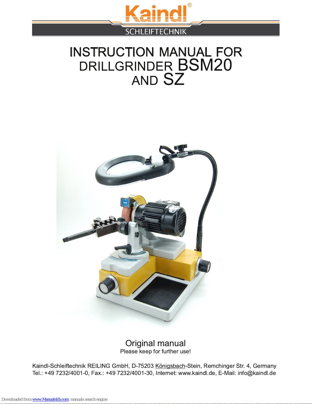
This mobile drill grinding machine made by Kaindl is unique as to its design and offers a
genuine alternative to bigger and considerably more costly equipments. Owing its solid
construction, its high precission, its small space requirement and its favourable price, the Kaindl
grinding machine is an indispensable auxillary equipment and a real measure of economy even
for single operation sections and for smaller workshops. The machine facilitates the adjustment
and the resharpening of twist drills to that extend, that everybody will be able to resharpen drills
with every lib angle that is imaginable. Form the prism reversing process results automatically
the highest precision and cutting egde symmetry. The well planned conception and the
possibility of an easy change of all party subject to wear, preserve the Kaindl drill grinding
machine as an indespensable aid in your work-shop. Even after many years of employment.
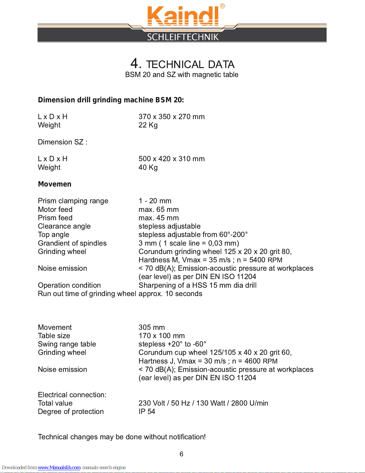
BSM 20: Range 1 - 20 mm (prism), complete with CBN-grinding wheel and optical lens
LED lighted.
SZ: with corundum cup wheel and grinding table with electro magnet, diamond cup wheel,
diamond dresser and optical lens LED lighted.
1 7073 CBN grinding wheel ø 1 25 mm grit B1 26/3, covered on 3 sides, broad 20 mm
1 6490 CBN grinding wheel ø 1 25 mm grit B76/3, covered on 3 sides, broad 20 mm (standard)
1 7556 CBN grinding wheel ø 1 25 mm grit B46/3, covered on 3 sides, broad 20 mm
1 0895 Corundum grinding wheel 1 25 x 20 x 20 grit 60 (coarse)
1 0890 Corundum grinding wheel 1 25 x 20 x 20 grit 80 (standard)
1 0891 Corundum grinding wheel 1 25 x 20 x 20 grit 1 80 (very fine)
1 0893 Corundum grinding wheel 1 25 x 05 x 20 grit 1 00 (HSS wood bits)
1 0896 Corundum cup wheel grit 60 (standard) for SZ
1 0897 Corundum cup wheel grit 80 (medium) for SZ
1 0898 Corundum cup wheel grit 1 00 (fine) for SZ
1 5422 rinding wheel support
1 4581 Diamond grinding wheel D 76, covered on 3 sides for carbide wood drills
1 4580 Diamond grinding wheel D 76, covered on 3 sides for carbide drills
11 223 Diamond cup wheel D 1 26 (standard) for SZ
1 0887 Diamond cup wheel D 76 (fine) for SZ
1 0906 Universal clamping device for single-lip cutters, cut off tools, etc. for SZ
1 0889 Magnetic depth stop for cutters
1 0875 Countersink sharpening device SVR 20 with collet 1 0 mm
1 0877 Collet 6 mm for SVR 20
1 0878 Collet 8 mm for SVR 20
1 0879 Collet 1 2 mm for SVR 20
1 0901 Morse taper sleeve MK1
1 0902 Morse taper sleeve MK2
2.1 BASIC EQUIPMENT BSM 20 / SZ
3. ACCESSORY AND SPARE PARTS BSM 20 / SZ

4. TECHNICAL DATA
BSM 20 and SZ with magnetic table
Dimension drill grinding machine BSM 20:
L x D x H 370 x 350 x 270 mm
Weight 22 Kg
Dimension SZ :
L x D x H 500 x 420 x 31 0 mm
Weight 40 Kg
Movement Drill grinding machine:
Prism clamping range 1 - 20 mm
Motor feed max. 65 mm
Prism feed max. 45 mm
Clearance angle stepless adjustable
Top angle stepless adjustable from 60°-200°
randient of spindles 3 mm ( 1 scale line = 0,03 mm)
rinding wheel Corundum grinding wheel 1 25 x 20 x 20 grit 80,
Hardness M, Vmax = 35 m/s ; n = 5400 RPM
Noise emission < 70 dB(A); Emission-acoustic pressure at workplaces
(ear level) as per DIN EN ISO 11 204
Operation condition Sharpening of a HSS 1 5 mm dia drill
Run out time of grinding wheel approx. 1 0 seconds
Grinding table
Movement 305 mm
Table size 1 70 x 1 00 mm
Swing range table stepless +20° to -60°
rinding wheel Corundum cup wheel 1 25/1 05 x 40 x 20 grit 60,
Hartness J,Vmax = 30 m/s ; n = 4600 RPM
Noise emission < 70 dB(A); Emission-acoustic pressure at workplaces
(ear level) as per DIN EN ISO 11 204
Electrical connection:
Total value 230 Volt / 50 Hz / 1 30 Watt / 2800 U/min
Degree of protection IP 54
Technical changes may be done without notification!
6

5. ENERAL SAFETY ADVISE
5.1 DUTY OF TAKIN CARE BY THE USER
7
The drill grinding machine BSM 20 / SZ has been designed and constructed under
consideration of an endangering analysis and careful selection of observed harmonized
norms, as well as further specifications.
The BSM 20 / SZ meets the state of the art and grants a maximum of safety.
This safety can only be achived in daily work, when all necessary steps are taken.
It is the duty of taking care by the user to plan and control these steps.
The user expecially has to take care that:
• the BSM 20 / SZ is used as directed (see chapter "description")
• the machine is used in flawless workable condition, especially that the safety
installations are checked
• requested personal security equimpent for the operator is available and used
• the operation manual is always in a readable condition, complete and available
near the machine BSM 20 / SZ
• the drill grinding machine BSM 20 / SZ operated only by personnel that knows the
contained operating instructions and the safety information
• Carrier active implants (pacemakers) must meet the safety distance of 20 cm
between the magnetic table of the sharpening center SZ and the position of the
implant
• all safety and warning instructions are not removed from the machine and kept
readable
Persons having not familiarized with the security advises, described herein, can't operate
the machine.

6. DESCRIBTION OF SAFETY SYMBOLS
8
In this instruction manual, the following safety symbols are used.
These symbols shall attract the readers attention to the text next to the symbols.
These symbols indicate that there is an existing danger to live and health of persons.
The lens cover of the magnifying lamp has to be closed after use :
Protect eyes while grinding, against kicked around particles
eneral danger
Before changing the grinding wheel or moving disconnect from electric
current
Caution:
Lens cover always must be
kept close when not in use
(danger of fire by sunbeam)

7. BASIC SAFETY OPERATIONS
Keep information on-hand:
This instruction manual has to be kept beneath the machine. It has to be granted, that all
persons working on the machine have access to the instruction manual. Additionally
there should be provided special advises in sence of a safe workplace.
All safety and operation labels on the machine should be keep in good condition and
readable. Damaged or non readable labels have to be replace immendiately.
These symbols indicate that there is an existing danger to live and health of persons.
9
For all grinding works with BSM 20 / SZ always wear safety glases.
rinding dust may hurt your eyes.
Only remove the grinding wheel protection for changing the wheel.
Never operate the machine with complete grinding wheel protection.
Before changing the grinding wheel or moving, disconnect from electric
current!

8. REQUEST TO THE OPERATIN PESONAL
1 0
Only persons who are familiar with this manual are allowed to work with this machine.
9. SPECIAL KIND OF DAN ER
Before starting the machine, the following jobs have to be done:
• Check the machine for visible dammage and eliminate ascertainend defects.
• The operation of the machine is only permitted in flawless condition.
• Electrical connections have to be checked regularly.
• Fix loose connection.
• Dammages electric cables have to be immediately replaced an electrician.
• Never clean electric parts with water or simmilar liquids.
Changes on the machine:
Due to safety reasons changes on the machine without permission are not allowed.
Only use original - spareparty, - original wear parts original accessories. These parts are
especially designed for this machine.

1 0. SET UP
11
Environmental conditions for set up
Use the drill grinding machine / Tool sharpening center only in dry rooms.
Environmental temperature from +5 to +50°C.
Humidity: up to 90%, not condensing
The BSM 20 / SZ is a table version.
Pay attention that the machine has a safe stand on the work table.
The place has to grant a vibration free running on the machine.
The machine is delivered in a box on a pallet (approx. 50 Kg).
The machine has to be lifted outside diagonal, BSM 20 approx. 25 Kg; SZ approx. 40 Kg
Remove transport locks (only for SZ)
1 0.1 TRANSPORT
Transport locks
After you have unpacked
and placed the machine
on a work table, please
remove the transport
locks. (see picture)
11 . HINTS FOR DISPOSAL OF PACKIN MATERIAL
The carton can be recycled and is for paper waste.
The rest of the packing is for non recycling waste.

1 2. START UP
In order to prevent dammage to the machine or injuries, please pay attention to the following
items before starting:
•Check that all tools or part not belonging to the machine have been removed before
starting.
•Sound test, assembly and removal of the grinding wheel (see page 28)
•Also read the chapter " eneral safety advise".
•Wear protective glasses.
•Check electric components for dammage (sight check).
•Check guidance for soft turning.
•Check fixed parts.
1 2
1 2.1 CHECKS BEFORE FIRST START UP

Fixation screw e.g.
web thinning
Clamping
lever
Prism support
Prism
rest
Wing screw
Prism
rinding wheel
motor switch
Right - Left Running
Clearance angle
adjustment
Motor feed
Prism feed
Scale tip angle
1 3. DESCRIPTION OF PARTS
1 3

1 4
Alignment of drill:
The reversing prism has a clamping range from
2-20 mm
. Open the prism by turning the
knurled screw. Place the drill in the prism.
Let project the drill around approx.
20-25 mm
outside the prism clamp. Close the prism
carefully with the knurled screw, pay attention the the drill still can still be turned. Align
one cutting edge between both graduation lines (see picture). Now tighten the prism with
the knurled screw by hand (without use of force). The drill is know aligned and ready to
sharpen.
Slide prism with the drill onto the prism support and fix with the wing screw. Adjust the
requested top angle (standard
118°
) on the prism support an fix with the clamping lever.
• right part-scale: support to right stop dog (slot) and adjust clearance angle.
• left part-scale: support to left stop dog (slot) and adjust clearance angle.
It does not matter which part-scale you use. The clearance angle is adjusted by the scale
for the clearance angle.
•
Direction 3
= more clearance angle
•
Direction 1
= less clearance angle
The clearance angle is adjusted by the clearance angle scale.
1 4. RINDIN OF RI HT HAND DRILLS
Move the drill to the front side of the grinding wheel, by using the prism feed and the
motor feed. By carefully feeding with the prism feed and meantime turning the prism
upside down, grind the first cutting edge completely. Note the graduation No. on the
scale, feed back, remove and turn the prism, place again in the prism support, fix it and
grind the second cutting edge to the same graduation as noted.
1 5. RINDIN OF THE DRILL
main cutting edge

1 5
1 5.1 RINDIN OF LEFT HAND DRILLS
rinding wheel: depending on sort of drill: use corundum and diamon wheel.
Adjustment on the machine.
Tip angle: 11 8°
For grinding of left hand drills, the prism rest an clearance angle adjustment hast to be
changed (Picture A).
Remove the prism support from the clearance angle adjustment and screw together on
the provided fixation threat (L) for left hand drills (Picture B).
Clamping screw
A
B
L
R

1 6
Let project the drill approx.
15 mm
out of the prism.
Align one cutting edge parallel to the gaduation mark for left hand drills (Picture).
Adjust the request clearance angle on the scale (Picture).
Applicative scale range for left hand grinding: 2-3.
2
= slight clearance angle
3
= high clearance angle
Move the drill to the front side of the grinding wheel, by using the prism feed and the
motor feed. By carefully feeding with the prism feed and meantime turning the prism
upside down, grind the first cutting edge completely. Note the graduation No. on the
scale, feed back, remove and turn the prism, place again in the prism support, fix it and
grind the second cutting edge to the same graduation as noted.
RINDIN OF THE DRILL
Clamping screw
raduation line for left
hand drills

Clearance angle
to max minus
Prism rest to
Pos.
A1
1 7
1 5.2 WEB THINNIN OF DRILLS
Lock points
A:
Lock point for cutter, carbide drill.
crossfacet shape, four surface shape
B:
Lock point for back or free
sharpening
C:
Lock point for web thinning
Keep the prism support, as described before. Turn the clearance angle adjustment to 1
(see picture below). Fix the turning mechanism in hole
C
of the fixation plate (see picture
below). Shift the complete prism tretle to the left stop, adjust on mark
A1
.
By using the motor- and prism feed, grind inside the drill behind the drill cutting edge.
Note the graduation No. on the prism feed scale and go back for
3 complete
turns. Do
not chance the position of the motor feed. Open the clamping lever, reverse the prism, fix
again and thin the web of the other side.
A
B
C

1 8
1 5.3 WEB THINNIN SPLIT -POINT
After sharpening, do not chance the position of drill in the
prism. Place clearance angle to position
2
(see picture
1 ). Fix the swivel mechanism in boring
C
(see picture 2).
Place the tip angle to
A2
(see picture 3).
In combination of prism feed and motor feed, sharpen
the first side of the drill on-hook (see picture 4). Note the
graduation mark of the motor feed and then move back
to the left away from grinding wheel. Turn the prism for
180°
and move forward to the same graduation mark as
before. The drill should look like on the picture above.
A
B
C
Picture 2
Picture 3 Picture 4
Picture 1

1 9
1 6. RINDIN OF CROSS CUTTIN OR
4FACET DRILLS
1 6.1 RINDIN OF A CUTTER
Depending of the drill is made of, use the corresponding grinding wheel.
Align one cutting edge parallel to both graduation lines (see picture).
Project the drill
approx. 20 mm outside
the prism. Fix the turning
mechanism in hole
A
(see picture below).
Adjust the top and clearance angle to your specifications. rind the first
side over the right edge of the grinding wheel by feeding the prism and
moving with the motor feed. The second side is ground with the same
adjustments. For grinding the back, fix the turning mechanism in hole
B
.
The grinding operation is the same as for the first two cutting edges.
Align the cutter to the
straight line of the prism
Cutter grinding is slightly different to cross facet grinding. But the adjustment and
alignment is identical to the 4 facet drill. The dirrerence in only the top angle adjustment.
Here use
180°-185°
(see picture below).
The shaprening procedure is identical. For cutters with more then two cutting edges use
the magnetic depth stop, listed under special accessoires. For cutters with odd cutting
edges (e. g. 3-cutters) each cutting edge has to be adjust separately. Having cutters with
even numbers of cutting edges, the opposite is cutting edges can by ground by reversing.
A:
Locking for main
cutting edge
B:
Locking for free
sharpening Prism rest
180° - 185°
A
B
C

20
1 7. STEP DRILLS
rinding wheel: Depending on the drill, use corundum or diamond wheel.
ATTENTION! Only step drills with two steps can be sharpened!
rinding of the 1 . Stufe (tip): Alignment and sharpening as for right hand drills
(see picture below).
The second step is adjusted in length and side direction as twist drills.
The tip angle is adjusted on the prism support.
Clearance angle as per your request.
rind the second step over the right side of the grinding wheel.
Alignment of the tip Alignment of the step
This manual suits for next models
1
Table of contents