used.
9. Disconnect the electrical power before servicing,
whenever changing accessories or when general
maintenance is done on the machine.
10. Maintain all machine tools with care. Follow all
maintenance instructions for lubricating and the changing
of accessories. No attempt shall be made to modify or
have makeshift repairs done to the machine. This not only
voids the warranty but also renders the machine unsafe.
11. The machinery must be anchored to the floor.
12. Secure your work. Use clamps or a vise to hold your
work, when practical. It is safer than using your hands and
it frees both hands to operate the machine.
13. Never brush chips away while the machine is in
operation.
14. Keep work area clean. Cluttered areas invite
accidents.
15. Remove adjusting keys and wrenches before turning
the machine on.
16. Use the right tool. Don’t force a tool or attachment to
do a job it was not designed for.
17. Use only recommended accessories and follow
manufacturers instructions pertaining to them.
18. Keep hands in sight and clear of all moving parts and
cutting surfaces.
19. All visitors should be kept at a safe distance from the
work area. Make your workshop completely safe by using
padlocks, master switches, or by removing starter keys.
20. Know the tool you are using — its application,
limitations, and potential hazards.
General Electrical Cautions
This machine should be grounded in accordance with the
National Electrical Code and local codes and ordinances.
The work should be done by a qualified electrician. The
machine should be grounded to protect the user from
electrical shock.
Wire Sizes
Caution: For circuits that are a great distance from the
electrical service box, the wire size must be increased in
order to deliver ample voltage to the motor. To minimize
power losses and to prevent motor overheating and
burnout, the use of wire sizes for branch circuits or
electrical extension cords according to the following table
is recommended:
Safety Requirements for Abrasive
Sanding Machines
Abrasive sanding can be hazardous to operators and
bystanders. Sanding sparks, chips and dust particles
thrown off by the sanding disc can cause serious injury if
contacted or inhaled. To avoid such injuries you must
comply with the following safety requirements:
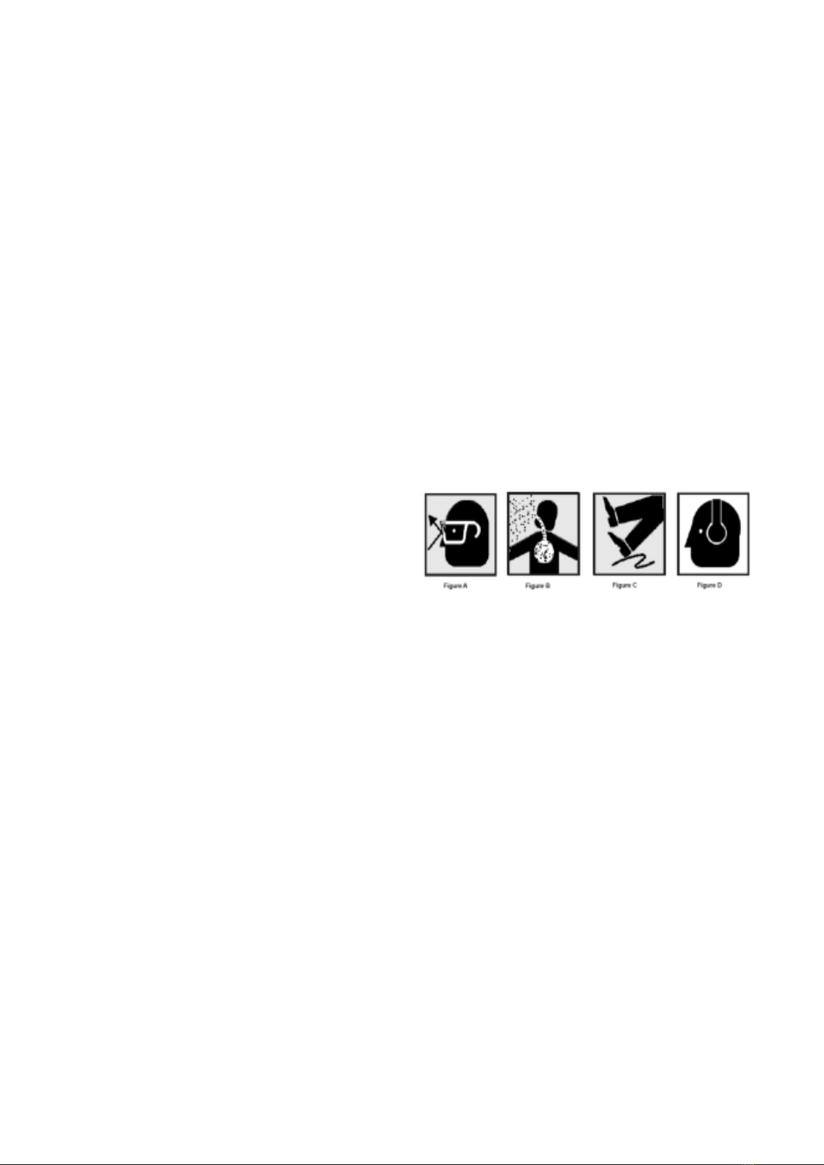
1. Always wear protective eyewear when operating
machinery. Eye wear shall be impact resistant, safety
glasses with side shields which comply with ANSI Z87.1.
Use of eye wear which does not comply with ANSI Z87.1
specifications could result in severe injury from the
breakage of the eye protection.
2. Wear leather safety gloves, arm guards, leather aprons
and safety shoes.
3. A dust collection system is recommended, The operator
should also wear a dust mask at all times.
4. Additional precautions may be necessary for sanding
materials which are flammable or have other hazardous
properties. You should always consult the manufacturer of
such materials for instructions on sanding and handling.
5. Do not force or jam the workpiece into the sanding disc.
6. Before sanding, always allow the motor to come up to
operating speed, then check the sanding disc for wobble,
runout, or any unbalanced condition. If the disc is not
operating accurately and smoothly, immediately stop the
motor and make repairs before attempting any sanding
operations.
7. Abrasive discs must be stored in a controlled
environment area. Relative humidity should be 35% to
50% and the temperature should be between 60oand 80o
Fahrenheit. Failure to do so could cause premature disc
failure.
8. Examine the face of the sanding disc carefully.
Excessive sanding that wears down to the backing
material can tear the disc. Never use a disc which shows
backing, nicks or cuts on the surface or edge or damage
due to creasing or poor handling.
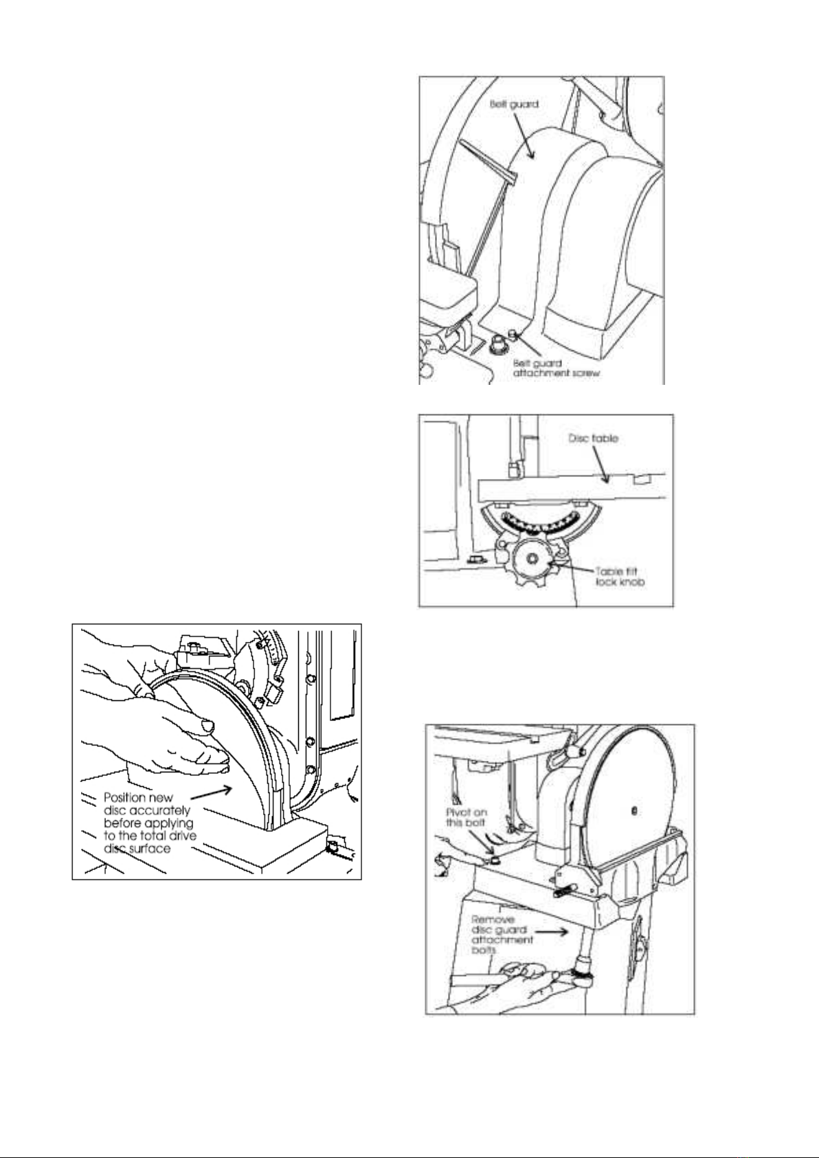
9. When installing a new disc, be certain the disc is
accurately centered on the drive wheel. Failure to do so
could cause a serious unbalanced condition.
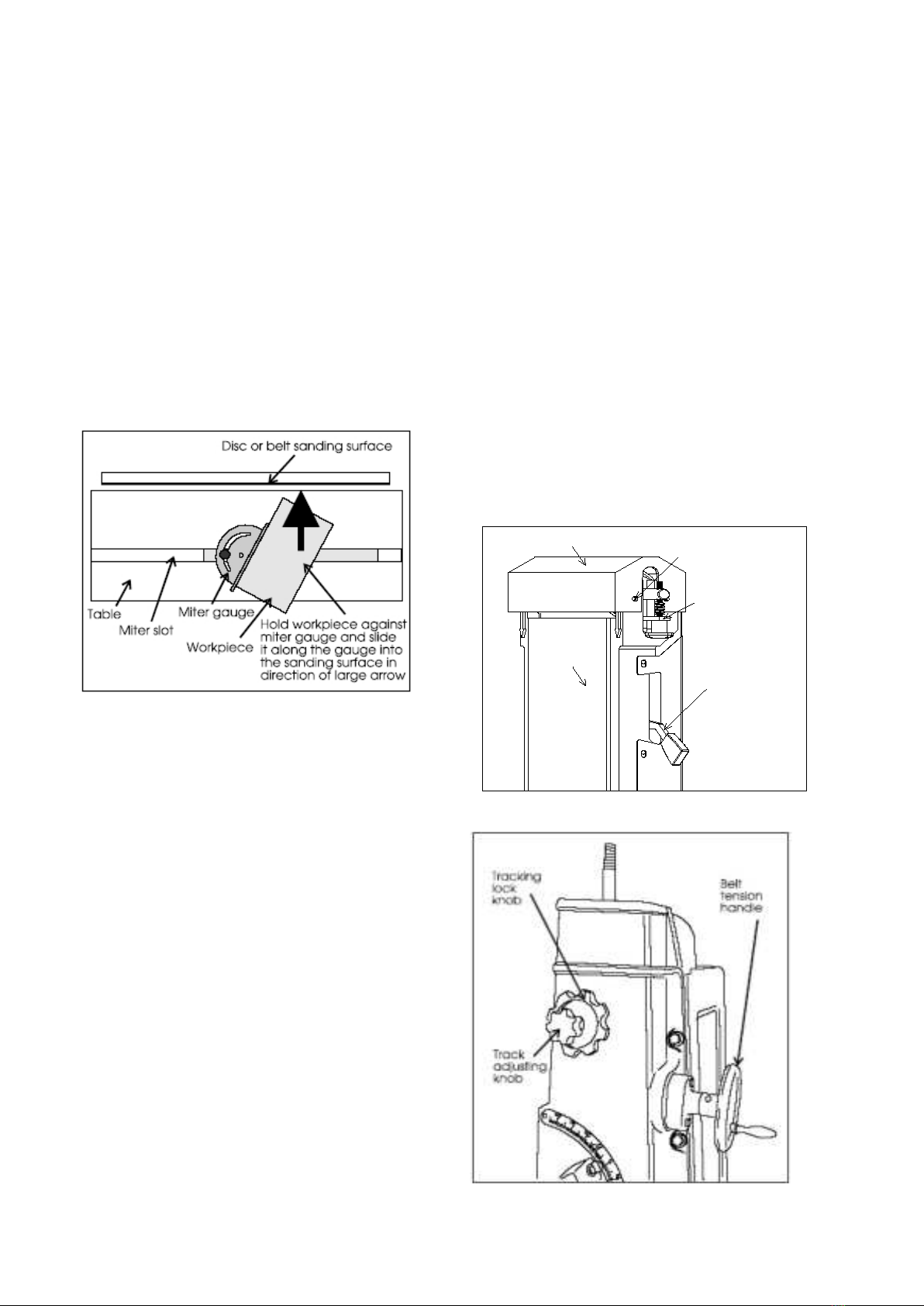
10. Always present the workpiece to the wheel while
resting the workpiece firmly on the table. Failure to do so
could result in damage to the workpiece or throwing of the
workpiece off the wheel.
11. Safety shoes which comply with ANSI Z41.1 should be
worn.
12. Personal hearing protection such as ear plugs or ear
muffs should be used to protect against the effect of noise
exposure.
Operating
Instructions
These sanders can be used to remove stock from a
wide variety of machinable materials. Different materials
require different grit types and grades to achieve the
desired stock removal rate and surface finish. Please
consult with your abrasive materials supplier for specific
recommendations on the correct grit material and grade
required for your specific needs.
When removing stock from soft materials (wood,
plastic, etc.) these machines are typically called
"sanders." When removing stock from hard materials (cast
iron, steel, etc.) they are referred to as "grinders". The
word "sander" is used, more-or-less consistently,
throughout this manual. It refers to the machines and not
the type of abrasive finishing being performed.
Before operating your sander, please read the basic
instructions on safe machine usage on the preceding two
pages.
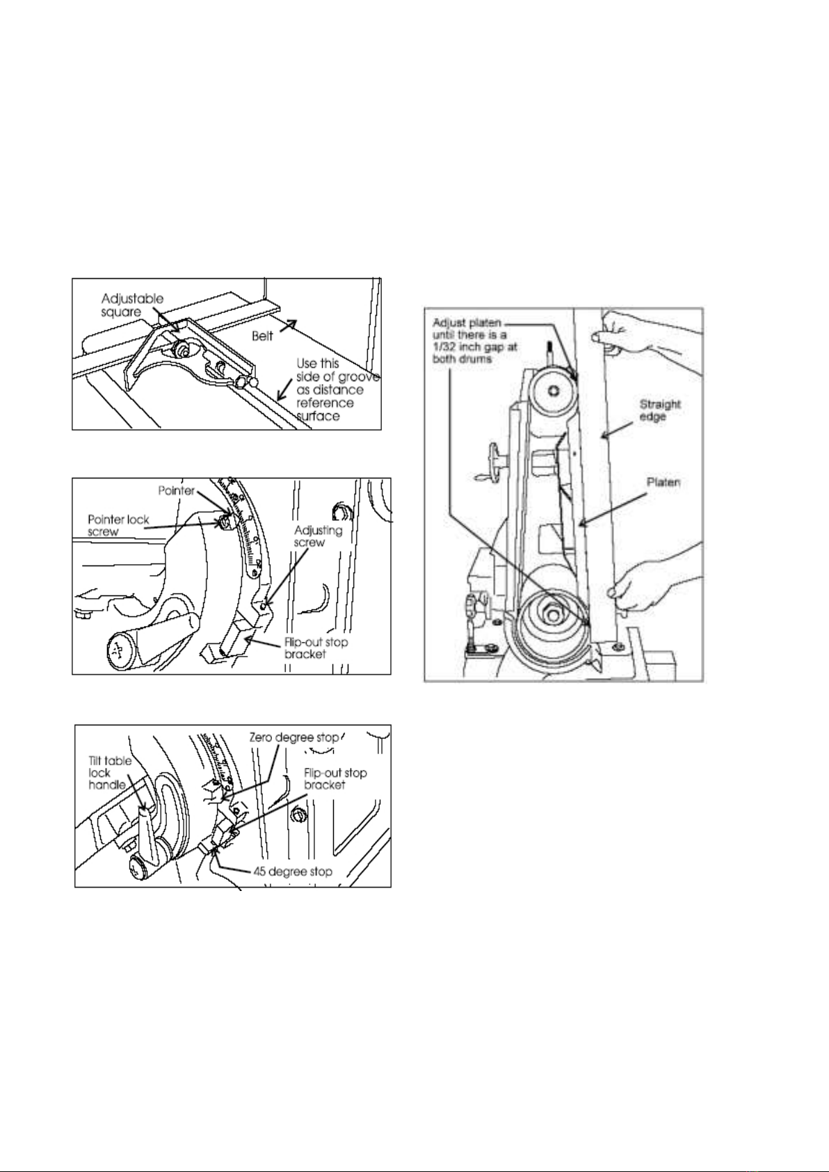
Belt Sander
The sanding belt must be in good condition, at proper
tension, and tracking correctly, before doing any sanding,
grinding or other abrasive machining operations. Refer to
the section on Track Mechanism Maintenance if you have
any problems with belt tension or tracking.
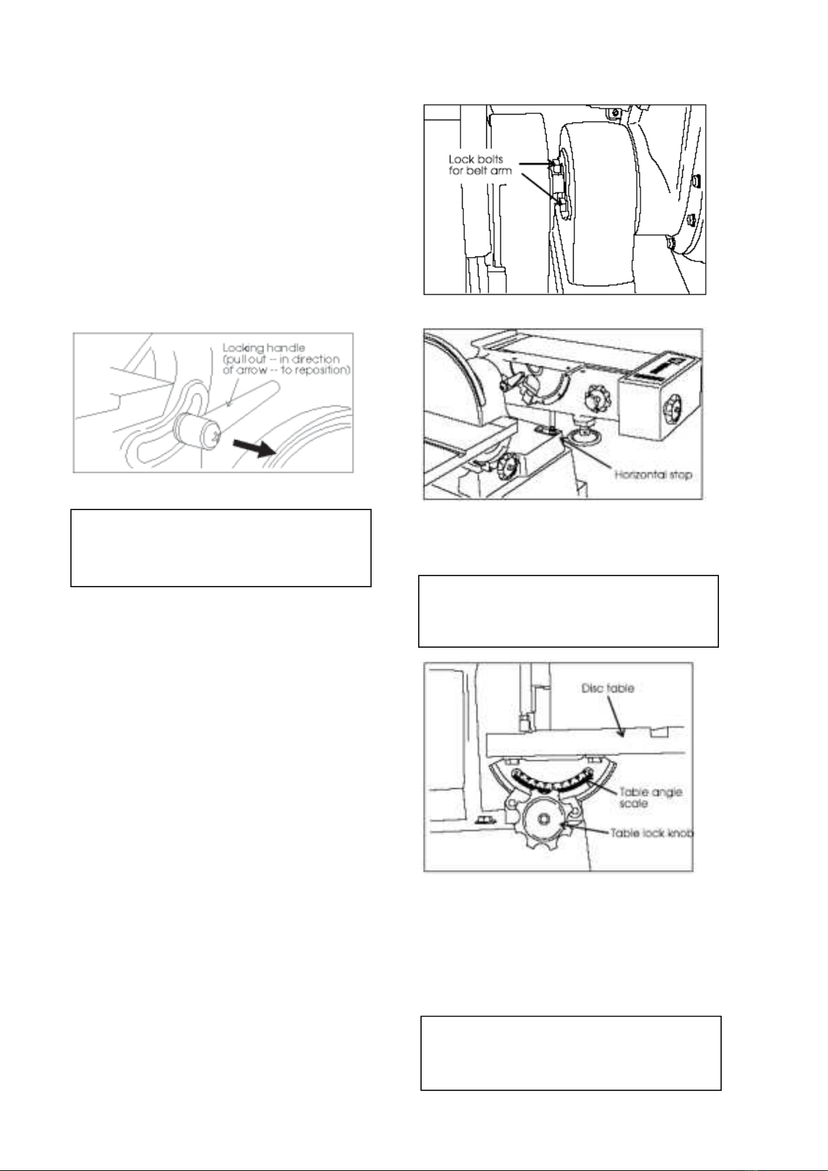
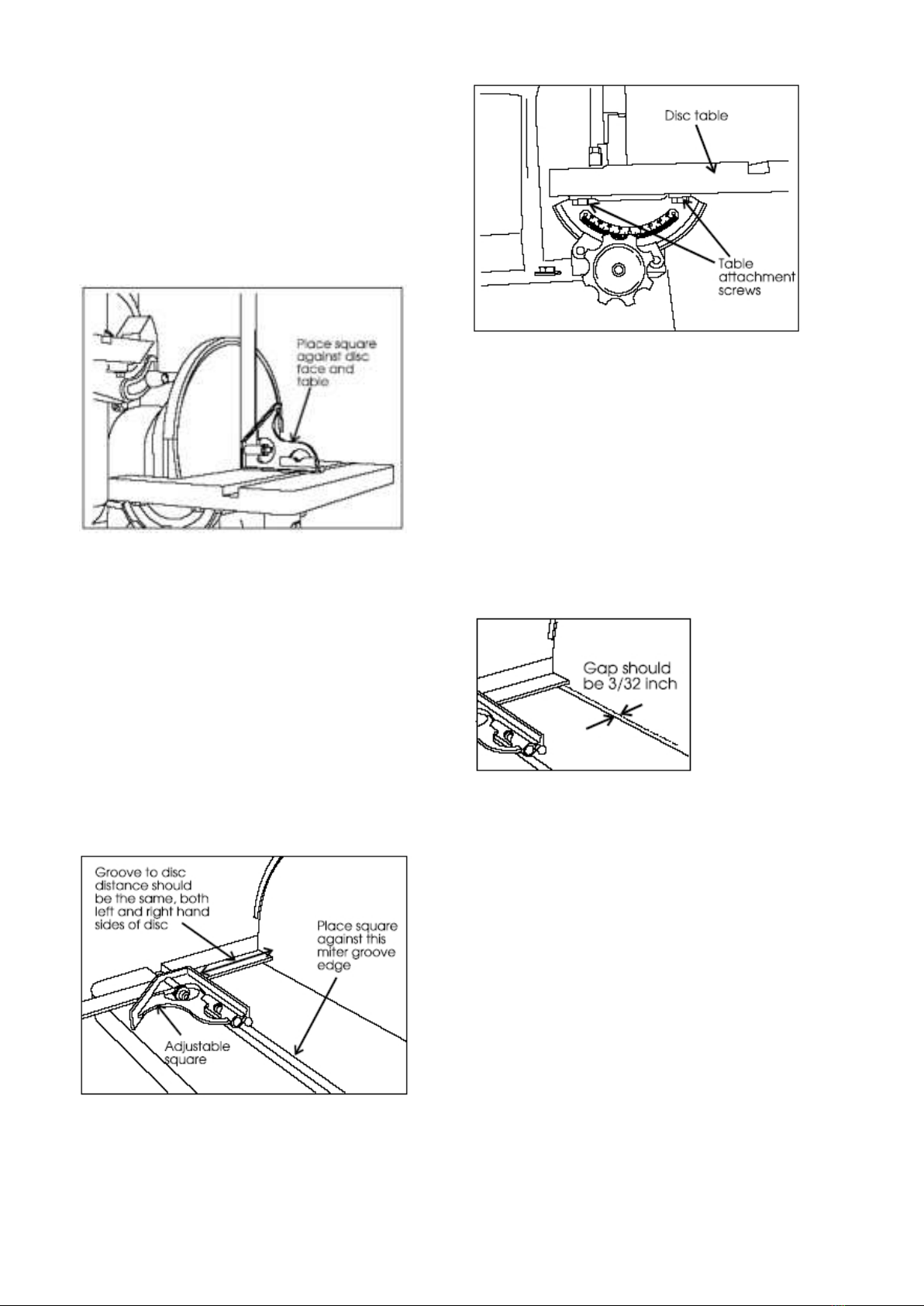
Adjusting the Belt Sander Table