K&M Analog Designs Two-Rock Jet Signature User manual

Two-Rock
Jet
Signature
OWNERS MANUAL

Thank you for your purchase of a Two-Rock amplier
from K&M Analog Designs, LLC.
As a discerning guitarist, you know the road to
great tone begins with great components.
Our Classic Design, carefully selected parts and
hand-built approach combine to make an extremely
versatile instrument.
Please take the time to read this manual. We
hope it will answer any questions that you may have.
We extend a warm welcome to you as a member
of a select group of musicians who have chosen a
Two-Rock amplier.

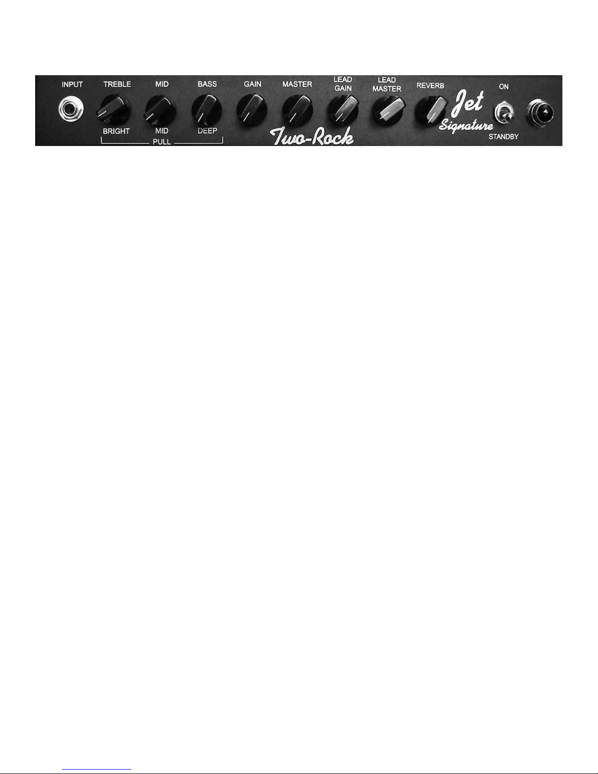
Input Jack- High impedance input to the amplier. Plug in your instrument here.
Push/Pull Treble Control- Adjusts the high frequency response. In the full counter-clockwise posi-
tion, high frequencies are bypassed to ground. In the full clockwise position, high frequencies are
allowed to pass to the next gain stage. When the knob is in the “out” position, the high frequency re-
sponse is boosted. This is most effective when the input gain is set at 12 o’clock or lower. The effect
is less dramatic as the input gain control is adjusted past the 12 o’clock position.
Push/Pull Mid Control- Adjusts the mid-range response. In the full counter-clockwise position, the
tone will be somewhat “scooped” of mid-range response, emphasizing the highs and lows. In the full
clockwise position, mid-range frequencies are allowed to pass to the next gain stage. When the knob
is in the “out” position, the mid range frequency response is boosted.
Push/Pull Bass Control- Adjusts the bass response. In the full counter-clockwise position, low fre-
quencies are cut. In addition, the response of the treble and mid-range controls is greatly reduced. In
the full clockwise position, low frequencies are allowed to pass to the next gain stage. When the knob
is in the “out” position, the low and low-mid frequencies are boosted. This is a low frequency contour
switch, changing the low and low-mid response.
Input Gain- Adjusts the overall gain of the amplier. Start with this control in the 12 o’clock po-
sition. Keep in mind that the amount of gain set here determines the signal level feeding the lead
channel. Low gain settings of this control will require higher lead gain settings for the same amount of
overdrive.
Master Volume- Adjusts the output level of the clean and lead channels.
Lead Gain- Adjusts the input level (gain) of the lead channel.
Lead master- Adjusts the output level of the lead channel.
Reverb- The front panel reverb control is the return, or mix, control. The reverb effect is defeated
with this control in the full counter clockwise position. Use in conjunction with the reverb drive con-
trol (see REAR PANEL FUNCTIONS, next page).
Stand-by Switch- Should be in the “down” or “stand-by” position when you apply power to the unit.
After a few seconds, place the switch in the “up” position to use the amplier. You may leave the unit
“powered up” and place this switch in the “stand-by” position to mute the output.
Indicator Lamp- This lamp will illuminate when the power switch is in the “up” position, indicating
the unit is receiving A/C power.
Front Panel Functions

A/C Input- Connects the amplier to A/C power via the power cord supplied. Unless otherwise
specied, your amplier is designed to operate on 120 volts A/C, 60 cycles, ONLY!
Fuse- See Fuse Chart
Power Switch- Turns power on.
Speaker Output Jacks- There are 2 speaker output jacks. Nominal impedance is 4-8 ohms. NEVER
OPERATE YOUR AMPLIFIER WITHOUT A PROPER SPEAKER LOAD CONNECTED. Be sure to
match the impedance of your cabinet with the impedance (output) of the amplier.
Reverb Drive- The reverb drive control adjusts the signal level applied to the reverb unit. Low set-
tings will provide a smooth, short decay effect, simulating small to medium rooms. Higher settings
will increase the decay time. At maximum clockwise rotation, an extremely wet reverb effect can be
created. This control is used in conjunction with the front panel (return) control (see FRONT PANEL
FUNCTIONS, previous page). The reverb effect is defeated with this control in the full counterclock-
wise position.
Effects Send- Use this jack to send the ampliers signal to outboard effects.
Effects Return- Use this jack to connect the output of your effects to the amplier.
Footswitch Jack- The footswitch connects here. The clean/lead and tone bypass functions can only be
activated via the footswitch.
4 8
Rear Panel Functions

V1- 12AX7, Rhythm channel
V2- 12AX7, Lead Channel
V3- 5751/12AT7, Reverb Driver
V4- 12AX7, Reverb/effects
V5- 12AX7. Phase Inverter
V6,V7- 6V6GC/6L6GC, Output
Fuse Chart
All Fuses are 3AG Type 250 Volt, SLO-BLO
Export 220, 230, 240 Fuses:
1- Jet and Jet Signature
Export 100 Volt/Domestic
2- Jet and Jet Sigmature
v4
Front
Back
v1
v3
v2 v5
Bias Test Point
Bias Adjustment
Power
Transformer
Output
Transformer
Reverb
Trans-
former
v6 v7
Each ne production tube is tested and matched to our exacting specications. External bias adjustment and
test points are located on the chassis near the output tube sockets. A digital voltmeter and small screwdriver are
required for bias adjustment.
BIAS ADJUSTMENTS:
Power up unit and connect proper speaker load.
Set master volumes and effects return controls to zero.
DO NOT apply any signal to the input during the biasing procedure!
Take unit off standby and allow a few seconds for the circuit to stabilize.
Set voltmeter to Millivolt scale (or lowest volt scale 60 millivolts=.060 volts.)
With meter grounded to chassis and + probe at test point, measure voltage.
A reading of 0.055 to 0.060 volts is normal for 50 Watt ampliers with (2) 6L6’s. A reading of 0.115 to 0.120
volts is normal for 100 Watt ampliers with (4) 6L6’s. If not in this range, adjust by turning bias screw SLOW-
LY a small amount. Do not set above .070!
For other tube types (5881, 6550, EL34) check with the manufacturer or contact us for recommendations.
Settings higher than .065 with 6L6 tubes may cause premature tube wear and possibly damage the amplier.
Keep in mind that tubes vary in quality, and some tubes can handle upwards of 40 ma each (a reading at the test
point of .080!) However, to be on the safe side, use the above as a guide.
NOTE: Some amps are equipped with 2 bias pots, one for low power, the other for high power. Adjust bias in
both hi and low power settings!
NOTE: Some amps are Class A/AB. In LOW POWER MODE(CLASS A), you will not get a proper reading-
adjust bias in high power mode only.
WARNING! No user serviceable parts inside! Refer to qualied service person only.
LINE CORD- For your safety, connect to grounded A/C receptacle only.
Tube Complement

PHONE: 1(707)584-TONE (8663) (M-F 9am-5pm PST)
FAX: 1(707)584-8661
ADDRESS: K&M Analog Designs, LLC
619 Martin Avenue, Suite 6
Rohnert Park, CA 94928
E-MAIL: Joe Mloganoski, Product Specialist
Bill Krinard, Chief Engineer
INTERNET: www.two-rock.com
PRECAUTIONS:
DO NOT expose to rain or any other moisture.
DO NOT use cleaning solvents. Wipe exterior with a clean, dry cloth
only.
Refer servicing to a qulied sevice technician.
K&M Analog Designs ampliers are brought to you by Bill Krinard and Joe Mloganoski.
We know your new Two-Rock amplier will provide many hours of enjoyment and inspira-
tion in the years to come. This manual is a resource for some of your questions. Please contact
us with any other questions or comments that you may have. We look forward to hearing from
you!

This is a product of
K&M Analog Designs, LLC
619 MARTIN AVENUE, SUITE 6
ROHNERT PARK, CA 94928
SERIAL NUMBER:_____________________________
Table of contents
Other K&M Analog Designs Amplifier manuals