Phonic MAR1 User manual

23
Service Manual
MAR1
Power Amplifier

1
SAFETY FIRST!
WARNING - TO REDUCE THE RISK OF FIRE OR ELECTRIC SHOCK, DO NOT EXPOSE THIS
APPLIANCE TO RAIN OR MOISTURE.
WATER AND ELECTRICITY DO NOT MIX. Keep this unit away from water. If water or other liquids
are spilled on or into this unit, unplug the power cord immediately from the wall socket (with DRY
HANDS) and get a qualified service technician to check it out before using. Keep this unit away from
heaters, radiators and other heat producing devices.
DO NOT ATTEMPT TO SERVICE THIS UNIT. ONLY A QUALIFIED SERVICE TECHNICIAN
SHOULD OPEN THIS UNIT FOR SERVICING.
CAUTION
RISK OF ELECTRIC SHOCK
DO NOT OPEN
The lightning flash with arrowhead symbol, within an equilateral
triangle, is intended to alert the user to the presence of
uninsulated “dangerous voltage: within the product’s enclosure
that may be of sufficient magnitude to constitute a risk of
electric shock.
The exclamation point within an equilateral triangle is intended
to alert the user to presence of important operating and
maintenance (servicing) instructions in the literature
accompanying the appliance.
CAUTION: TO REDUCE THE RISK OF ELECTRIC SHOCK, DO NOT REMOVE
COVER (OR BACK). NO USER-SERVICEABLE PARTS INSIDE. REFER
SERVICING TO QUALIFIED SERVICE PERSONNEL.
KEEP IT CLEAN: Dust, dirt and debris can interfere with the performance of this product.
Make a special effort to keep this unit away from dusty, dirty environments. Cover the
unit when not in use. Dust it regularly with a soft, clean brush. Careful attention to these
details will be time well spent, and this product will reward you with years of trouble free
operation.

2
Introduction
Congratulations on your purchase of the Phonic MAR 1 Reference Amplifier. Like other
Phonic MAR series power amplifiers –MAR 2/4/6, this unit is designed to provide a good
combination of power, audio clarity, reliability and durability. Especially, optimized for
studio monitoring applications and moderate-power live performance setups, the amps
main features include:
l150 watts per channel into 4 ohms, 100 watts per channel into 8 ohms
lFront panel LED Indicators for Protect, Clip & Signal
lDetented dB gain controls
lBuilt-in protection system for short circuit, DC, and temperature monitoring
lPower-up muting
l-26dB signal presence LEDs on each channel
lQuality Neutrik combo Input connectors for professional use
lStereo/Parallel switch
lGround floating switch
lMassive, custom-designed extruded heat sinks ( individual for each channel) for
cool operation
lNo Ventilation fan is needed, allowing for quiet operation and reduced ambient noise
in the studio.
lExtremely low noise and distortion, suitable for quiet applications such as recording
studio, church and museum.
Precautions
1. When first powering-up the amp, keep the amplifier Gain Controls all the way off, in
order to block potentially damaging or annoying sounds caused by defective cables or
hookups. When turning up the Gain, do it gradually, until normal operation is verified.
These precautions are necessary with all high-power amplifiers, since they have
enough power to blow most speakers in abnormal situations.
2. Check the AC Voltage before connecting the AC plug.
3. The amplifier is protected from surges in power-line voltage by the fuses. Should your
unit ever fail to power-up, first unplug the power cord, and then replace the fuse with
exact type and value.
About This Manual
Please be reminded that a power amplifier is a high-current, high-power device
and should be treated with respect and care. Please read this manual before
connecting and operating your unit and file it in a safe place for future reference.

3
MAR 1 Power Amplifier
Front Panel Description
1. Gain Controls
These two knobs are the level controls for
Channel one and two respectively.
Turning clockwise will increase its gain,
and counter clockwise will decrease its
gain. Please always power-up with the
volume all the way down, and increase
volume slowly to make sure that no
conditions exist which could annoy your
audience or harm your speakers.
2. Protect LED Indicator
The MAR1 features several types of
protection to prevent damage to the
circuitry during turn-on or fault conditions.
If the LEDs light up, this indicates that one
of the various protections is safeguarding
the different sections of the amplifier and
in these cases, the power output is
normally switched off until normal
operating conditions are restored.
lLoudspeaker protection: in the event
of malfunction, a sensor located on
the power outputs is able to break the
circuit avoiding that current peaks
reach the speakers and damage
them.
lThermal protection on the heatsink: If
the amp overheats, thermal shutdown
protects the circuitry until the
temperature is reduced to a safe
level.
lShort circuit protection: The Protect
LED Indicator will also light up if the
speaker terminals are short circuited,
or the impedance of the load is too
low. In these circumstances, the
Protect LED will stay on until the fault
condition is rectified.
Some protection situations require the
amplifier to be switched off and then
back on for normal operating
conditions to be restored.
3. Clip LED Indicator
The LEDs light up at clipping status,
whenever any conditions occur that could
leak to non-linearility, such as an out-of-
spec load and waveform distortion.
Because of the MAR 1’s ability to enter
and exit clipping with as few audible
artifacts as possible, you may not hear
any distortion even if the indicator flashes.
In general, a few flashes every now and
then will not be a problem. However, if
the LEDs flash often or remain on for any
extended period of time, then turn down
the volume controls to reduce the signal
level going to the MAR 1. If this doesn’t
5
1
2
3
4
4
solve the problem, check your output
cables and speakers.
4. Signal“Status”LED Indicator
Each channel of the MAR 1 features a
signal LED to show that there is an audio
signal at the input to the channel. The
threshold for the indicator is –26 dB,
which should be enough to avoid noise
triggering the LED.
5. Power Switch
The power ON/Off switch with an LED
indicator.
Always start with Gain Control (1) all
the way down before powering-up to
avoid abnormal sound from defective
cables or hookups.
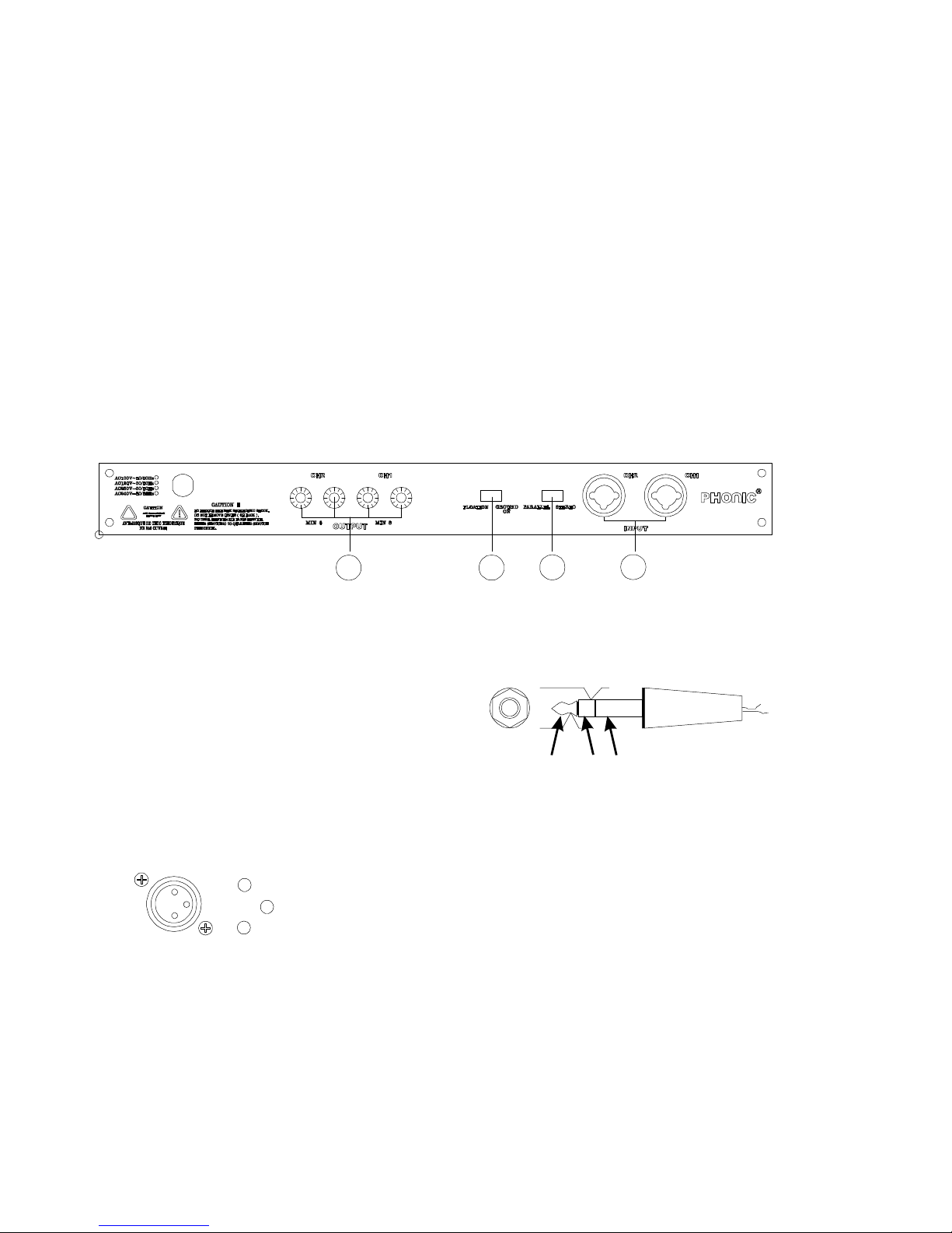
Back Panel Description
6. Ch1/Ch2 Input (Neutrik
Connector)
Quality Neutrik Connectors are provided
for balanced XLR and 1/4”inputs, which
are commonly, used for both mobile and
installation set-ups. They provide a good
combination of ease of connection and
resistance to corrosion. The XLR inputs
are wired as per the following convention:
These type of jacks feature on much
audio equipment and are convenient if the
amp is frequently connected and
disconnected, such as for mobile set-up.
The plugs used should wired as per
the following convention:
7. Stereo/ Parallel Switch
In Stereo operation, two separate signals
are treated separately by Channels 1 and
2 of the amplifiers.
In Parallel operation, One signal is
treated by both channel 1 and 2 of the
amplifier. In other words, a signal
connected to Input Ch1 or Ch2 (6) is sent
to both Output Ch1 and CH2 (9).
This switch should be used when the
+
-
gnd
tip ring sleeve
+
-gnd
6
7
8
9

5
Amplifier is off; otherwise the
speakers’components could be
damaged.
8. Ground Lift Switch
This switch allows the circuit and chassis
grounds to be separated in case on a
ground conflict. In normal use the switch
should be in the Ground On position.
Lifting the ground (Floating position) may
resolve the ground conflict, but which
means that circuit grounding depends on
other connected components.
Deficiencies in other components’
grounding will affect the sound and a
serious electric fault with the amplifier
could damage other components in the
system.
For the best combination of safety and
performance,it is highly recommended
to keep the switch in the “Ground On”
position,
9. Binding Post Output Ch1/ Ch2
These are suitable for banana plugs,
spade lugs or bare wires. Spade lugs and
bare wires should both be screwed done
tightly to exclude oxygen, and care should
be taken to avoid loose strands of wire
that may cause short circuits.
Speaker Speaker
6
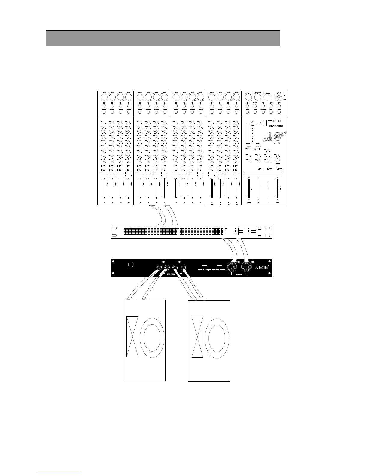
Hook-up #1 Studio Monitor Amp/ Sound Reinforcement
The MAR1 is ideal for driving near-field or other reference speakers. For auditorium and
live music use, the MAR 1 has sufficient power to drive a set of small-to-medium size club
speakers.
outputs
outputs
inputs
speakers
MAR1 amplifier
compressor or equalizer
PEQ3400
mixer
IMPACT16
7
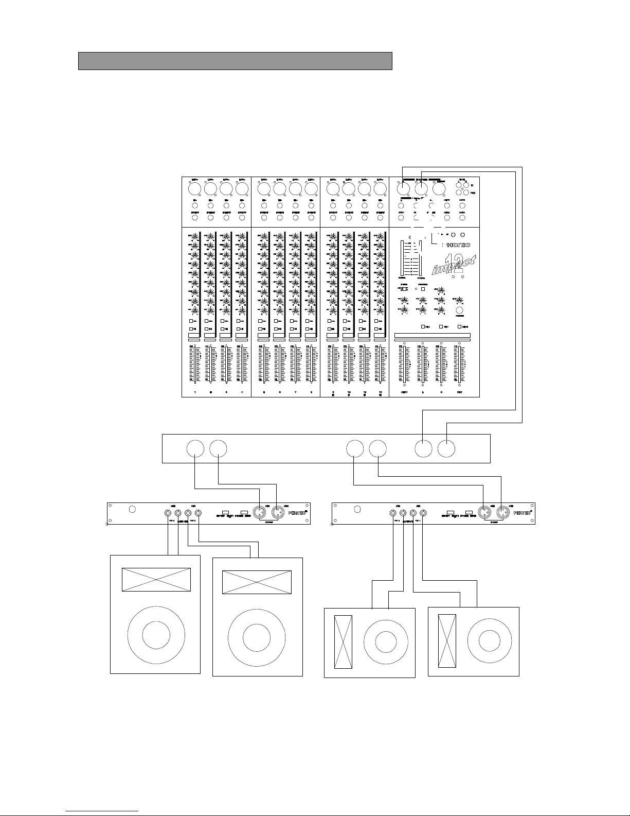
Hook-up #2 Bi-Amp Sound Reinforcement
Biamplification often provides better live sound and greater efficiency by splitting the audio
signal into two different channels. One MAR1 drives a low frequency speaker system and
the other, a high frequency speaker system.
Impact 12
Crossover
High
Frequency
Outputs
Low
Frequency
Output
Ins
High Frequency MAR1
Low Frequency MAR1
Low Frequency Speakers High Frequency Speakers

8
Specifications
Frequency response (1W/ 8 ohms) 20 –20kHz (+1 dB)
Power bandwidth (100W/ 8 ohms) 20 –20kHz (+1 dB)
Total harmonic distortion < 0.3 % (100W/8 ohms, 10Hz –20kHz)
<0.5 % (120W/4 ohms, 10Hz –20kHz)
Signal to noise ratio (IHF-A) > 100 dB
Slew rate 25 V/us
Damping factor
(Rate output: 100W/8ohms @1kHz) > 150
Crosstalk (Rate output: 100W/8ohms @1kHz) >75 dB
Rated Power
(8 ohms, both channel driven) 100W
Max. Output Power
4 ohms, 1kHz, 1% T.H.D. both drive
8 ohms, 1kHz, 1% T.H.D. both drive 150W
120W
Input sensitivity
8 ohms, 1kHz, @ rated power 100W 0.775V
Input impedance 30k ohms (balanced)
15k ohms (unbalanced)
Voltage Gain 31.2 dB
Max. Noise <0.6 mV
Protection circuits lOutput offset voltage protection
lHeat sink overheat protection
lTransformer overheat protection
lLoad shorting protection
lPower on/off protection
AC power requirement 120V/ 60Hz or 230V/50Hz
Dimensions (mm) 480x338x54(WxDxH)
Net Weight 9.5 Kg
E & OE. Due to continual product development, all features and specifications subject to change without notice

9
PC-Board Layout MAR1 Input / Output
&
Power Supply Board
Table of contents
Other Phonic Amplifier manuals

Phonic
Phonic XP 600 User manual

Phonic
Phonic MAX 250 User manual

Phonic
Phonic MAX 3500 User manual

Phonic
Phonic ZA200B User manual

Phonic
Phonic MAX 1000 User manual

Phonic
Phonic MAX 2500 plus User manual

Phonic
Phonic DMX802 User manual

Phonic
Phonic MAX 500 User manual

Phonic
Phonic POWERPOD 820 User manual

Phonic
Phonic PHA 4800 User manual

Phonic
Phonic XP1000 User manual

Phonic
Phonic XP 3000 User manual

Phonic
Phonic MAX 250 User manual

Phonic
Phonic CMx35 User manual

Phonic
Phonic XP 2000 User manual

Phonic
Phonic MAX 2500 plus User manual

Phonic
Phonic MAX 860 plus User manual

Phonic
Phonic iAMP3020DSP User manual

Phonic
Phonic DMX1501 User manual

Phonic
Phonic XP 2000B User manual


