Lightning: Before thunderstorms or other severe weather, disconnect the machine from wall
power (but to avoid life threatening lightning strikes, not during a storm). Similarly, before
any severe weather, disconnect all the power connections of other machines and antenna and
phone/network cables which may be interconnected so that no lightning damage or overload
results from such secondary connections.
Air circulation: Chassis openings offer ventilation and serve to protect the machine from over-
heating. Never cover or otherwise close off these openings. Never place the machine on a soft
surface (carpet, sofa, etc.). Make sure to provide for a mounting space of 4-5 cm/2 inches to
the sides and top of the unit when mounting the unit in racks or on cabinets.
Controls and switches: Operate the controls and switches only as described in the manual.
Incorrect adjustments outside safe parameters can lead to damage and unnecessary repair
costs. Never use the switches or level controls to effect excessive or extreme changes.
Repairs: Unplug the unit from all power and signal connections and immediately contact a quali-
ed technician when you think repairs are needed – or when moisture or foreign objects may acci-
dentally have gotten in to the housing, or in cases when the machine may have fallen and shows
any sign of having been damaged. This also applies to any situation in which the unit has not
been subjected to any of these unusual circumstances but still is not functioning normally or its
performance is substantially altered.
In cases of damage to the power supply and cord, rst consider turning off the main circuit
breaker before unplugging the power cord.
Replacement/substitute parts: Be sure that any service technician uses original replacement
parts or those with identical specications as the originals. Incorrectly substituted parts can
lead to re, electrical shock, or other dangers, including further equipment damage.
Safety inspection: Be sure always to ask a service technician to conduct a thorough safety
check and ensure that the state of the repaired machine is in all respects up to factory stan-
dards.
Cleaning: In cleaning, do not use any solvents, as these can damage the chassis nish. Use
a clean, dry cloth (if necessary, with an acid-free cleaning oil). Disconnect the machine from
your power source before cleaning.
Be very careful to check that the rear chassis power selection switch is set to the correct
local line voltage position before using the unit (230 V position: 220-240 V/50 Hz, 115 V posi-
tion: 110-120 V/60 Hz)! When in doubt about a source, contact your dealer or a professional
electrician.
Before connecting any equipment make sure that any machine to be connected is turned off.
Follow all safety instructions on pages 4 and 5 and read further information about the rear
sockets and switches on pages 8, 9 an 10.
Placement
Place the unit on a level and stable surface. The unit’s enclosure is EMC-safe and effectively
shielded against HF interference. Nonetheless, you should carefully consider where you place
the unit to avoid electrical disturbances. It should be positioned so that you can easily reach
it, but there are other considerations. Try not to place it near heat sources or in direct sunlight,
and avoid exposure to vibrations, dust, heat, cold or moisture. It should also be kept away
from transformers, motors, power ampliers and digital processors. Always ensure sufcient
air circulation by keeping a distance of 4-5 cm/2 inches to the sides and top of the unit.
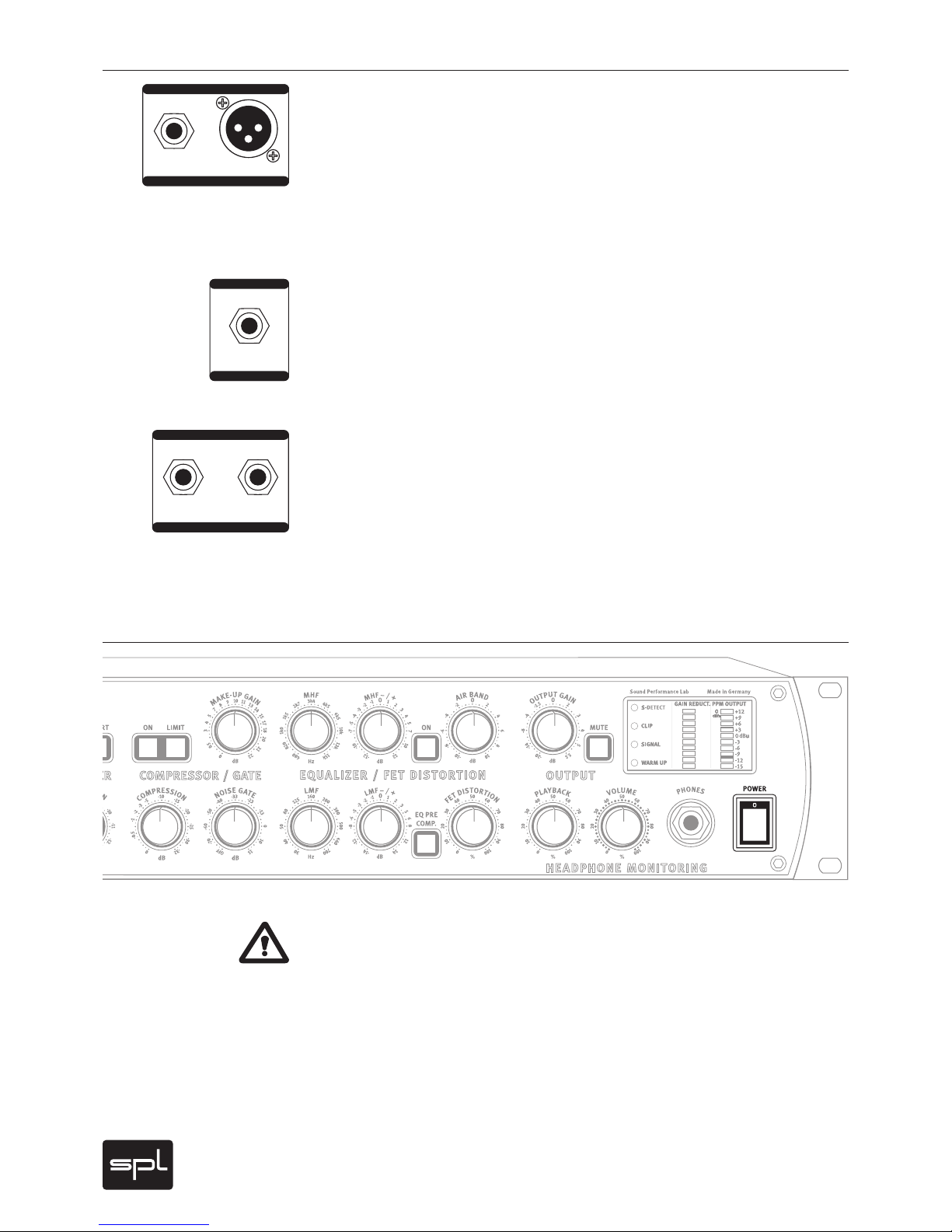
Important Security Information
Hook Up