K&S KS 14100HDE ATSR User manual

Please, read this manual
carefully before use! Owner’s Manual
DIESEL GENERATOR
KS 14100HDE ATSR
KS 14100HDE 1/3 ATSR
SILENT DIESEL GENERATOR
KS 14200HDES ATSR
KS 14200HDES 1/3 ATSR
HEAVY DUTY
diesel generator
ENG

1
TABLE OF CONTENTS
1. Preface _ _ _ _ _ _ _ _ _ _ _ _ _ _ _ _ _ _ _ _ _ _ _ _ _ __ 2
2. Diesel Generator Use and Safety Precautions_ _ _ _ _ _ _ _ _ _ _ 3
3. Symbols _ _ _ _ _ _ _ _ _ _ _ _ _ _ _ _ _ _ _ _ _ _ _ _ _ _ _ _ 5
4. Diesel Generator Overview, Conguration, Components _ _ _ _ _ _ _ 6
5. Specications
_ _ _ _ _ _ _ _ _ _ _ _ _ _ _ _ _ _ _
_ _ _ _ _ 7
6. Terms of Use of Diesel Generator _ _ _ _ _ _ _ _ _ _ _ _ _ _ _ _ 9
7. Check Before Getting Started_ _ _ _ _ _ _ _ _ _ _ _ _ _ _ _ _ _ 9
8. Control Panel _ _ _ _ _ _ _ _ _ _ _ _ _ _ _ _ _ _ _ _ _ _ _ _ _ _ 10
8.1. LED Display _ _ _ _ _ _ _ _ _ _ _ _ _ _ _ _ _ _ _ _ _ _ _ _ _ _ 11
8.2. Control Unit _ _ _ _ _ _ _ _ _ _ _ _ _ _ _ _ _ _ _ _ _ _ _ _ _ _ 12
9. Getting Started _ _ _ _ _ _ _ _ _ _ _ _ _ _ _ _ _ _ _ _ _ _ _ _ 17
10. Generator Start-up _ _ _ _ _ _ _ _ _ _ _ _ _ _ _ _ _ _ _ _ _ _ 18
11. Maintenance _ _ _ _ _ _ _ _ _ _ _ _ _ _ _ _ _ _ _ _ _ _ _ _ _ _ 20
12. Recommended Maintenance Schedule _ _ _ _ _ _ _ _ _ _ _ _ 21
13. Recommended Oils _ _ _ _ _ _ _ _ _ _ _ _ _ _ _ _ _ _ _ _ _ _ 21
14. Air Filter Maintenance _ _ _ _ _ _ _ _ _ _ _ _ _ _ _ _ _ __ _ _ 23
15. Fuel Filter Replacement and Cleaning _ _ _ _ _ _ _ _ _ _ _ _ _ _ 24
16. Battery Maintenance and Charging ___ __ __ _____ _ _ _ 25
17. Generator Storage _ _ _ _ _ _ _ _ _ _ _ _ _ _ _ _ _ _ _ _ _ _ _25
18. Troubleshooting _ _ _ _ _ _ _ _ _ _ _ _ _ _ _ _ _ _ _ _ __ _ _ 26
19. Average Power Consumption of Devices _ _ _ _ _ _ _ _ _ _ _ _ 27
20. WarrantyTerms _ _ _ _ _ _ _ _ _ _ _ _ _ _ _ _ _ _ _ _ _ _ _ _ 28
Abbreviations and acronyms:
KS Electric generator
D Diesel
E Electric start
S Soundproof housing
1/3 Single- and three-phase operation
H HEAVY DUTY

2
PREFACE
Thank you for your purchase of Könner & Söhnen HEAVY DUTY series
diesel generator. It is professional machinery with an increased service life and
is therefore suitable for heavy-duty operation.
HEAVY DUTY series diesel generator engines have a service life of more
than 3,000 operating hours subject to observance of the rules of generator
operation and the maintenance schedule.
This manual contains safety instructions, a description of the use and
commissioning of Könner & Söhnen generators and procedures for their
maintenance.
The generator manufacturer may make some modications that may not be
reected in this manual, namely, the manufacturer reserves the right to make
changes in the product design, conguration and construction. The images
and drawings in this manual are for reference only and may dier from the
actual components and inscriptions on the products.
Contact information that you are free to use in case of any problems can be
found at the end of this manual. All information in this manual is correct to the
best of our knowledge and belief at the date of its publication.
In order to ensure equipment integrity and avoid possible injuries,
we recommend that you read this manual before operating
the generator.
The current list of service centers can be found on the ocial importer’s
website:
www.ks-power.de
NOTE!
Do not operate single-phase and three-phase circuit breakers at
the same time to prevent electric shock and avoid damage to your
electrical devices and the generator!
(Circuit breakers are shown in Figs. 3 and 4)
IMPORTANT!

3
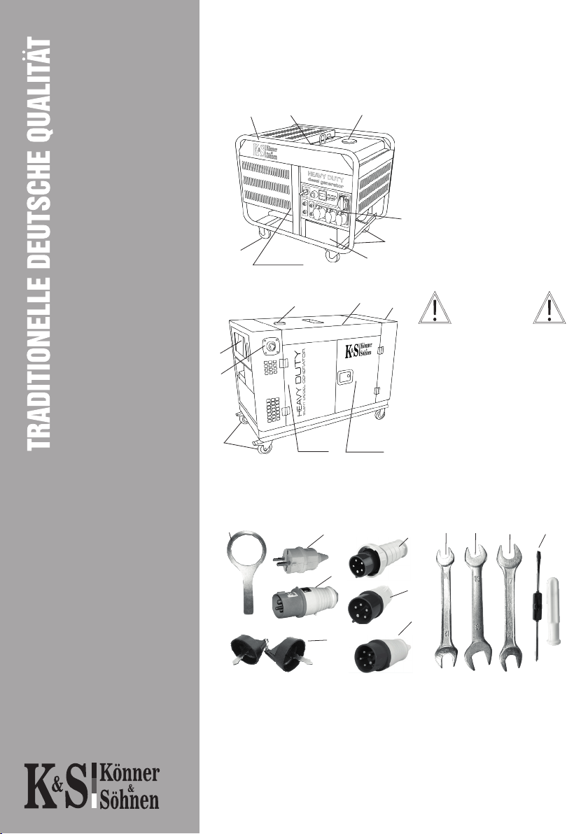
DIESEL GENERATOR USE AND SAFETY
PRECAUTIONS
Read this manual carefully before operating the generator.
Work Area
- Do not use the generator near ammable gases, liquids or dust. During
operation of the generator, its exhaust system becomes very hot.This may cause
re or explosion of these materials.
- Keep the work area clean and well lit to avoid injuries.
- Keep unauthorized persons, children and animals away from the running
generator.
Electrical Safety
- The generator produces electricity that can cause electric shock in the event
of failure to observe safety precautions.
- Avoid operating the generator in high-humidity environments. Do not allow
moisture to enter the generator, as this increases the risk of electric shock.
- Avoid direct contact with grounded surfaces (pipes, radiators, etc.).
- Be careful when working with the power cord. Replace it immediately in
case of damage, as damaged power cord increases the risk of electric shock.
- All generator connections to the mains supply must be carried out by a
certied electrician in accordance with all electrical codes and regulations.
- Connect the electric generator to the protective ground before operation.
- Do not connect/disconnect the generator to/from power consumers while
standing in water, on wet or damp soil.
- Do not touch live parts of the generator.
- Only connect the generator to the power consumers that correspond to the
electrical specications and power rating of the generator.
- Keep all electrical equipment dry and clean. Replace damaged or worn
wiring.Worn, damaged, or rusted terminals must be replaced as well.
Personal Safety
- Do not operate the generator when you are tired or under the inuence of
potent drugs, alcohol or medication. During operation, inattention can cause
serious injury.
- Avoid inadvertent start-up. Make sure the power switch is set to OFF when
turning o the generator.
- Make sure there are no foreign objects on the generator when it is turned on.
- Always keep proper footing and balance when starting the generator.
- Do not overload the generator; use it for its intended purpose only.
- Do not operate the generator in areas with poor ventilation. Exhaust gases
contain poisonous carbon monoxide, which is life threatening!

4
Operating and Maintaining the Generator
- Before preoperational check, make sure the generator is on a at, level surface
and the engine switch is in the OFF position.
- Check the connection of moving parts, inspect for damaged parts that aect
the operation of the generator. Eliminate damage before use.
- Use only recommended oils and fuels for maintenance and repair. The use of
other oils, consumables and spare parts deprives you of the right to warranty
service.
- The generator must be maintained by trained and qualied personnel only. For
the nearest service center, please contact your local dealer or refer to the current
list of service centers on the importer’s ocial website:
www.ks-power.de
- Store the generator in a dry, well-ventilated area if you are not using it.
The generator runs on diesel fuel.
Do not use gasoline or kerosene as fuel!
NOTE!
Do not operate single-phase and three-phase circuit breakers at
the same time to prevent electric shock and avoid damage to your
electrical devices and the generator!
(Circuit breakers are shown in Figs. 3 and 4)
IMPORTANT!

5
SYMBOLS
1234
5678
1. Be careful when operating the device! Observe
the safety instructions in this manual.
2. Operate the generator only in well-ventilated
indoor spaces or outdoors. Exhaust gases contain
2, whose vapors are life threatening.
3. Do not operate or store the device in high-
humidity environments.
4. Do not smoke while operating the generator!
5. The device generates electricity. Observe
safety precautions to avoid electric shock.
6. Read this manual carefully before operating
the device.
7. Do not touch the generator with wet or dirty
hands.
8. Observe re safety regulations; do not operate
the generator near open ame.
1 2 3
654
1. Wear protective rubber gloves when handling
the battery. The battery contains a dangerous
acid electrolyte. If electrolyte comes into contact
with skin or face, rinse immediately with plenty
of water and seek medical advice.
2. Do not operate the generator near open ame.
3. Keep children away from the generator work
area.
4. Note! The battery releases explosive hydrogen
while charging!
5. Read this manual carefully before operating
the device.
6. Wear safety goggles when operating the
generator.
9
9. Do not touch! The generator dampener
becomes hot during operation.
The device bears
information about
the guaranteed noise
level.

6
DIESEL GENERATOR OVERVIEW,
CONFIGURATION, COMPONENTS
Fig. 1
1.Reinforced frame
2.Fuel tank
3.Air lter
4.Antivibration mounts
5.Fuel lter
6.Oil lter
7.Oil dipstick
8.Oil drain hole
9.Engine safety switch
10. Battery
11. Control panel
12. Soundproof housing
13. Wheels
The manufacturer
reserves the right to make
changes in the product
design, configuration and
construction. The images in
this manual are for reference
only and may differ from
the actual components and
inscriptions on the products.
1. Generator
2. Packaging
3. Owner’s manual
4. Optional equipment:
Complete set:
1.Oil lter key;
2. 230V plug. 16 A/ (2+);
3.230V plug. 32 (2P+E);
4.230V plug. 63 (3P+E+N) - for models:
14100HDE ATSR, 14200HDES ATSR;
5.400V plug. 16 (3P+E+N) - for models:
KS 14100HDE1/3 ATSR, KS 14200HDES 1/3
ATSR;
6.400V plug. 32 (3P+N+PE) - for models:
KS 14100HDE 1/3 ATSR, KS 14200HDES 1/3
ATSR;
7.2x ignition keys;
8.1012 mm open end wrench;
9.1316 mm open end wrench;
10. 1417 mm open end wrench;
11. 6.0 mm 2 oset screwdriver.
11
10
4
2
1
2
11
9
1
13
12
5, 103, 6, 7, 8
13
3
5, 6, 7, 8
Fig. 2
2
7
3
5
6
48 9 10 11
1
IMPORTANT!

GENERATOR SPECIFICATIONS
7
Modell KS 14100 HDE
ATSR
KS 14100 HDE
1/3 ATSR
KS 14200 HDES
ATSR
KS 14200 HDES
1/3 ATSR
Voltage (V) 230 230 400 230 230 400
Max power required 12 kW 9 kW 12.5 kVA 12 kW 9 kW 12.5 kVA
Nominal power 11 kW 8.5 kW 11.8 kVA 11 kW 8.5 kW 11.8 kVA
Power factor, cosφ 1.0 1 .0 0.8 1.0 1.0 0.8
Frequency (Hz) 50 50
Maximum current (A) 52.17 39.13 18.06 52.17 39.13 18.06
Outlets
1*63
1*32
2*16
1*32 (3P)
1*16 (3P)
1*32
1*16
1*63
1*32
2*16
Kontaktband
1*32 (3P)
1*16 (3P)
1*32 ; 1*16
Kontaktband
Fuel tank volume, L 32 28
LED display voltage, frequency, working hours voltage, frequency, working hours
Noise level LPA/LWA, dB 71/96 72/97
Power output DC,V/ 12/8.3 12/8.3
Engine model KS 1020HD KS 1020HD
Engine type diesel powered two-cylinder,
four-stroke air-cooled diesel powered two-cylinder,
four-stroke air-cooled
Engine power hp/kW 21/15.45 21/15.45
Crank case volume, L 3 3
Engine capacity, cm3 997 997
Power output controller intelligent voltage stabilization system AVR
Uruchomienie Elektro Elektro
Accumulator, Ah 36 36
ATS output + +
The diameter of the frame 32 mm, round soundproof anti-vandal housing
Netdimensions
(L*W*H),mm 950*640*900 1250*650*890
Gross dimensions
(L*W*H),mm 1000*690*1020 1300*700*1010
Net weight, kg 220 325
Gross weight, kg 240 345
Protection class IP23M IP23M
Dopuszczalne odchylenie napięcia znamionowego – nie więcej niż 5%

8
NOTE!
Do not operate single-phase and three-phase circuit breakers at
the same time to prevent electric shock and avoid damage to your
electrical devices and the generator!
(Circuit breakers are shown in Figs. 3 and 4)
To ensure the reliability of the generator and increase its lifespan, the peak
capacities may be slightly limited by circuit breakers.
The optimum operating conditions are ambient temperature of 17 – 25 °C,
barometric pressure of 0.1
MPa (760 mm Hg), and relative humidity of 50 – 60%. Under such ambient
conditions, the generator can guarantee maximum performance in terms of the
stated specications. In case of deviations from the above ambient values, the
performance of the generator can be dierent.
Please note that in order to preserve the lifespan of the generator, continuous
loads should not exceed 80% of the rated power.

9
It is recommended to ground the generator before operating it for the rst time.
Before starting the device, remember that the total power of the connected power
consumers should not exceed the rated power of the generator.
Types of Power Consumers and Start-up Current
There are two types of power consumers (electrical devices connected to the
generator): active and reactive. Active power consumers include all power
consumers, whose power input is converted into heat (heaters).
Reactive power consumers include all power consumers equipped with an electric
motor. When starting the engine, start-up current occur briey, the magnitude
of which is based on the engine design and purpose. The magnitude of occurring
start-up currents should be considered when selecting a generator.
Most electric tools have a start-up current ratio of 2-3. This means that the
operation of such tools requires a generator, the power of which is 2-3 times the
power of the connected power consumer. Power consumers such as compressors,
pumps, washing machines have the highest start-up current ratio.
CHECK BEFORE GETTING STARTED
Checking the fuel level
1. Unscrew the fuel cap and check the fuel level in the tank.
2. Fill fuel to the level of the fuel lter and make sure there is no air in the fuel
system.
3. Tighten the fuel cap securely.
Fig. 2
Checking the oil level (Fig. 2)
1. Unscrew the oil dipstick and wipe it
out with a clean cloth.
2. Insert the dipstick without screwing
it in.
3. Check the oil level by a mark on the
oil dipstick.
4. Add oil if its level is below the mark
on the oil dipstick.
5. Tighten the oil dipstick.
FILL TO
THIS
LEVEL
TERMS OF USE OF DIESEL GENERATOR

10
Be sure to charge the battery before operating the models equipped with
electric starters. Charge the battery with an optional charger (not included),
or allow the generator to operate at 50% load for at least one hour when
operating for the rst time.
The type of diesel fuel must comply with the operating season!
CONTROL PANEL
Fig. 3
1. Single-/three-phase switch
(position 1 - 400 V, position 0 (OFF),
position 2 - 230 V)
2. Ignition switch
3. LED display for models KS 14100HDE
ATSR and KS 14100HDE 1/3 ATSR
(Fig. 4) and Multifunction control unit
for models KS 14200HDES ATSR
and KS 4200HDES 1/3 ATSR (Fig. 5);
4. Circuit breakers
5. Fuse for 12V connector
6. 12 V connector
7. Oil level indicator
8. ATS output
9. Outlets
10. Ground connector.
7 8 910
65
12 3 4
IMPORTANT!

11
LED display
for models KS 14100HDE ATSR and KS 14100HDE 1/3 ATSR
Fig. 4
To select the indicators, press (M) button. The selection of indicators is cyclic.
The selected mode is highlighted by the corresponding icon.
(V) - this mode displays the voltage level of the
generator in volts
(Hz) - this mode displays the frequency of the
generator in Hertz
(1) - this mode displays the generator operation
time from start-up in minutes.
(2) - this mode displays the total operating
hours of the generator.

12
Fig. 5
CONTROL PANEL.
MAIN FUNCTIONS OF CONTROL BUTTONS.
Multifunction control unit
for models KS 14200HDES ATSR and KS 14200HDES 1/3 ATSR
Generator start-up.
Generator manual start-up.
Automatic mode.
Press this button to switch the control unit to automatic
mode.
Manual mode.
Press this button to switch the control unit to manual mode.
Press and hold down this button to disable the manual
mode.
Generator stop.
Pressing this button stops the generator in the manual
operation mode. With the cooling operation enabled,
pressing this button will immediately turn o the generator.

13
Up.
Scrolls page up or increases a parameter value.
Down.
Scrolls page down or decreases a parameter value.
Reset.
In case of malfunction of the generator, the system is
blocked; press this button to delete the error message:
the user can turn o the generator if the error message is
displayed.
Escape.
Press this button to move one menu level up and cancel the
parameter change.
Enter.
Press this button on the home page to enter the main menu.
Press this button in the main menu to open a submenu.
Press this button in the submenu to enable the changed
parameter.
Red Generator malfunction
O Normal generator operation
Green LED glows steadily: manual mode
enabled.
Green LED glows steadily: automatic mode
enabled.
LED INDICATORS

14
Warning!
This symbol indicates a possible risk of injury, death, or
serious damage to equipment if safety precautions for
device installation, operation, or maintenance are not
observed.
Caution!
This symbol indicates a possible risk of injury or damage
to equipment if safety precautions for device installation,
operation, or maintenance are not observed.
Note!
System status message or help message.
Warning!
Failure to observe the instructions below may
result in serious injury, death, or serious damage
to equipment.
The control unit must be installed, operated and maintained
by qualied personnel who have received appropriate
training in operation of high voltage equipment. Measuring
devices must be installed in accordance with local and
national electrical codes and regulations.
• The engine and other devices must be equipped with
speed limiters to prevent damage to power control
equipment, which can lead to accidents or damage.
• Speed limiters must be completely independent of the
power source of the power control system. At the same
time, provision should be made for emergency shutdown in
the event of overtemperature and oil pressure drop.
Caution!
First turn o the generator, and then turn o the battery.
The control unit uses electrically induced components to
prevent damage to such components.
It is strictly forbidden to open the back cover of the control
unit and touch electronic components on the boards or wires.
DESCRIPTION OF SYMBOLS
SAFETY PRECAUTIONS

15
1. RUN STATUS/CURRENT STATUS
NOWMODE/CURRENT MODE AUTO/AUTOMATIC MODE
GENSTATE/GENERATOR STATUS READY/READY FOR USE
AUTOSTART/AUTOMATIC START DISABLED/DISABLED STATUS
SPEED/SPEED 1500RM/1500 RPM
2. GEN STATUS/GENERATOR PARAMETERS
P 10.0KW F 50Hz
I 10.0 10.0 10.0A
L-N 220 220 220V
L-L 220 220 220V
3. ENGINE/ENGINE
OIL PRESSURE / OIL PRESSURE +++bar
CABINTEMP / HOUSING TEMPERATURE +++ C
FUEL LEVEL / FUEL LEVEL +++%
OILTEMP / OIL TEMPERATURE +++ C
. ALARMS/ALARM MESSAGES
Press the « » or « », button to check the data or parameters
in real time.
Press the « » button on the home page to enter the main menu, as shown in
the gure.
GENERAL DISPLAY MENU:
DISPLAY
1 2 3
4
SUBMENU:

16
MAIN MENU PARAMETERS ARE GIVEN INTHE TABLE BELOW
First level menu Second level menu
Current status Current status
NOWMODE / CURRENT MODE AUTO / AUTOMATIC
MAN / MANUAL
OFF / DISABLED
GENSTATE / GENERATOR
STATUS
NOT READY / NOT READY
READY / READY
PRESTART / PRESTART
CRANKING / STARTER
CRANK INT / INTERVAL BETWEEN AUTOMATIC
START-UPS OF THE GENERATOR
START IDLE / IDLE START
RUNNING / IN OPERATION
ONLOAD / LOADED
COOLING / COOLING
STOPPING / SHUTDOWN
UTOSTART/RMTSTAR
AUTOMATIC/REMOTE
STARTUP
ENABLED / ON
DISABLED / OFF
SPEED / ROTATIONAL
SPEED
Current engine speed e.g. / Current engine
speed (for example,1500 RPM/1500
REVOLUTIONS PER MINUTE)

17
GETTING STARTED
Before starting the engine make sure that the power rating of tools or power
consumers corresponds to that of the generator. Do not exceed the rated power
of the generator. Do not connect any devices before the engine start!
Commissioning
In the rst 20 operating hours of the generator, the following requirements should
be met:
1. During commissioning, do not connect power consumers, the power of which
exceeds 50% of the rated (operating) power of the device.
2. Be sure to change the oil after the rst 20 operating hours. It is better to drain oil
while the engine is still hot after operation to ensure quick and complete oil draining.
Use care when the generator is running:
- You can operate the generator if the voltmeter shows a value of 230V +/-10% (50
Hz); and a value of 400V +/-10% (50 Hz) for three-phase generators.
- Monitor the voltmeter and stop the generator if the value is too high.
- Only connect to a DC outlet to charge the battery. When charging batteries, pay
attention to the correct polarity (plus/+ to plus/+, minus/- to minus/-).
- First connect the charger cable to the battery and only then to the generator.
The generator should be connected to the mains supply by a skilled electrician.
Connection errors can cause serious damage to equipment.
- Do not use a voltage of 12 V concurrently with 230 V (400 V for three-phase
generators).
To stop the engine, proceed as follows:
1. Disconnect all the devices connected to the generator, set the circuit breaker to OFF.
2. Allow the generator to operate at idle for 3 minutes so that the alternator cools
down.
3. Set the ignition key to OFF.
4. For models KS 14200HDES ATSR and KS 14200HDES 1/3 ATSR, engines have safety
switches (Fig. 1, no. 9). Use it only in an emergency.
In the power supply mode, the generator should operate no longer
than 30 minutes in the range from rated to maximum power.
Do not change the controller settings in terms of the amount
of fuel or speed governor (this adjustment was made at the
factory). Otherwise, this may result in changes in the engine
operation or its failure. Any modications in the generator design
deprive the user of the right to warranty service!
IMPORTANT!
ATTENTION - DANGER!

18
STARTING THE GENERATOR
- Do not connect any power consumers to the generator before the engine start.
- Connect the terminals to the battery and pay attention to the correct polarity
(plus/+ to plus/+, minus/- to minus/-).
- Set the ignition key to ON.
- Turn the key clockwise to the START position.
- After a successful start, release the key and it will automatically return to the
ON position.
- If the engine doesn’t start after pressing and holding down the key in the
START position for 5 seconds, wait 15 seconds before the next attempt to start.
Lengthy operation of the engine start system may discharge the battery. While
the generator is running, leave the key in the ON position.
- After three minutes of the generator operation, switch the circuit breaker
(circuit breaker Fig. no. 4) to the upper position (ON).
Before connecting devices to the generator, make sure that they are in good
condition. If the device that was connected suddenly stopped or failed,
immediately disconnect the power using a circuit breaker (Fig. 3, no. 4),
disconnect the device and check it.
Do not connect of two or more devices simultaneously.
The start-up of many devices requires high power.
Devices should be connected in turn according to their power rating.
Do not connect any power consumers within the rst 3 minutes
after the generator start.
If the engine does not start after three or four attempts, this may
mean that air has entered the fuel system. Remove air from the fuel
system (drain diesel fuel together with excess air).
IMPORTANT!
ATTENTION - DANGER!

19
Disconnect all devices before stopping the generator! Do not stop the
generator if it has any devices connected to it.
This may disable the generator!
Connecting Power Consumers
After switching on the generator, make sure that the voltmeter readings correspond to
the nominal ones (230V +/-5% @ 50 Hz for single-phase generator and 400V +/-5%
50 Hz for three-phase generator).
KS 14100 HDE 1/3 ATSR та KS 14200 HDES 1/3 ATSR
diesel generator models are suitable for 230 V power consumers
(single-phase generators) and 400 V power consumers (three-
phase generators). Mode switching is allowed only when no power
consumers are connected.
Using as a three-phase generator:
The three-phase diesel generator should have the power distributed to all three
phases, and the power must be balanced at all phases.The power at each of the three
phases must not exceed 1/3 of the total power of the generator.The balance tolerance
should not exceed 20%.
If only1 or2 phasesareloaded,the generator willfail.The totalpowerand total current
at all three phases must not exceed the normal load and amperage of the generator.
Failure to comply with these requirements may damage the primary
and secondary windings and the AVR unit.
If the overload resulted in automatic operation of the generator
circuit breaker, reduce the load. Repeated power-on of the generator
is possible 5 minutes after disabling.
NOTE!
Do not operate single-phase and three-phase circuit breakers at
the same time to prevent electric shock and avoid damage to your
electrical devices and the generator!
(Circuit breakers are shown in Figs. 3 and 4)
IMPORTANT!
IMPORTANT!
IMPORTANT!
This manual suits for next models
3
Table of contents
Other K&S Portable Generator manuals