- 32 -
NOTE: WHERE NOT EXPRESSLY INDICATED, THESE INSTRUCTIONS ARE REFERRED TO ALL MODELS
General information
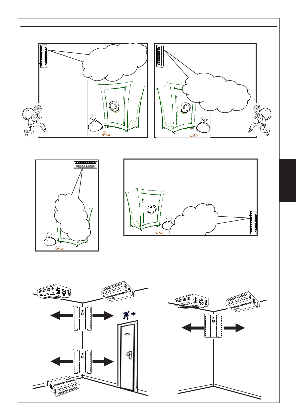
In a few seconds Foggy is able to create a fog effect that makes it impossible to move within rooms, forcing the ill-
intentionedpersontoimmediatelysearchanescaperoute.Combinedwithanintrusiondetectionsystem,itcompletes
effectiveness of the detection through and “active” protection of the area.
Thecontinual system monitoring alwayskeeps liquid level, boilertemperature, battery status andnetwork presence
under control; Foggy is also equipped with a safety thermostat that deactivates the system in case of overheating.
Harmless to persons and property
The fog created by Foggy is completely harmless and suitable for use in residential, commercial, industrial and
military field of application. It is ideal for protecting property that is sensitive and valuable such as what is found at
jewellers, electronics ands computer stores and warehouses.
Thefog disperses without leavinganyresidue. Intense verifications, carried out atspecialised analysis laboratories,
guarantee the non toxicity of this effect that is also used bylaw enforcement agencies for fire simulations.
Duration of the fog effect
Within at least 10 seconds, Foggy 30 is able to saturate a 100 m³ environment, while Foggy 50, in at least 20
seconds, is able to saturate a 200m³ environment;it will take approximately 20 / 30 minutes to recuperate complete
visibility. In order to obtain a fog effect that lasts over time, it is possible to enable a particular function that activates
a maintenance deployment impulse.
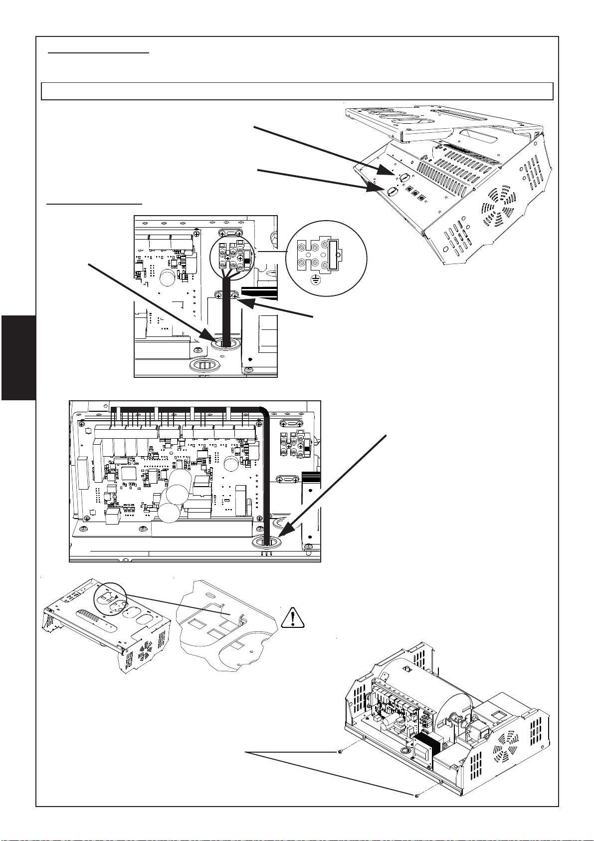
Connections
Foggy can be the natural completion of any installed intrusion detection system. It is pre-set with a series of free
inputs that allow interfacing with any control unit.
Foggyhas an available equippinginput that allows following theon/off status of thecontrol unit in order toguarantee
that it cannot be activated while the system is shut off. Besides this, there is also a double consent that acts as a
guarantee against accidental activation of the fog generator. For example, it is possible to activate the pre-alarm
usingthe relay fromthe intrusion detection controlunit and connectthe actual alarm inputto an autonomous sensor
in the environment protected by Foggy.
Besides these inputs, Foggy includes free contact control outputs dedicated to:
Anti-removal alarm, Liquid level, System disbursing, Technical malfunction with an indication on the display for No
network, Battery level, Battery failure, Pump malfunctioning, Board temperature, Boiler temperature.
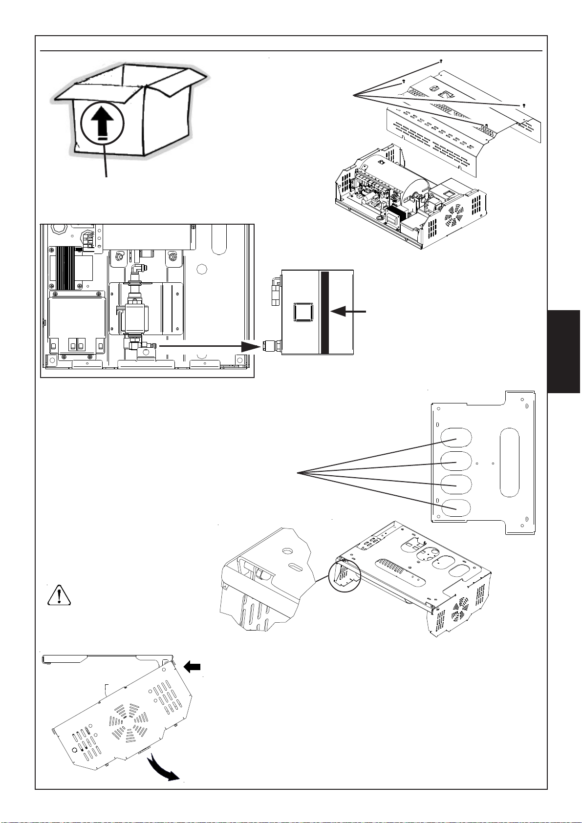
FOGGY Fog generator
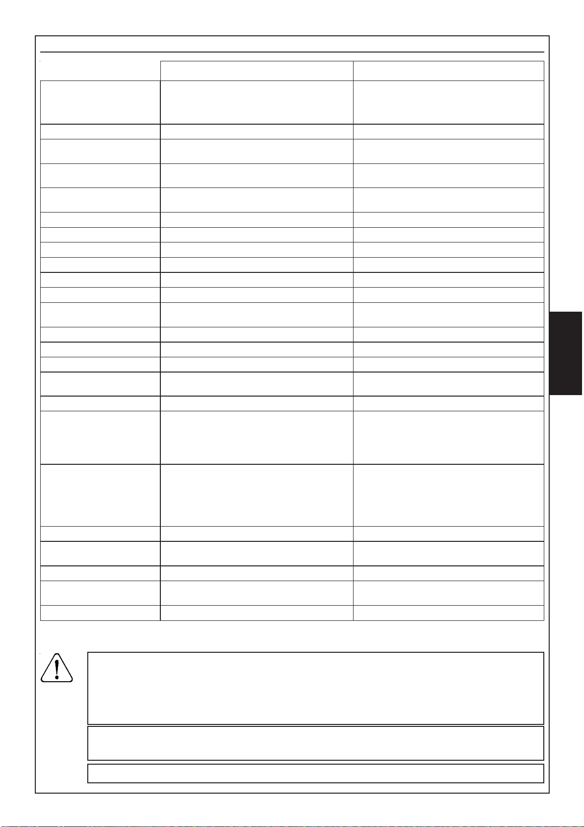
FOGGY Dimensions
264 mm163 mm
358 mm
165 mm
480 mm
FOGGY 30 FOGGY 50
354 mm