K&W Model Airplanes De Havilland DH4 1916 Bomber User manual

de Haviland DH4B ARF 1
Assembly Manual
for ARF stand-off scale model in 1:5 scale.
Historical data and presentation.
Model design and drawing by
Göran Kalderén ©
2002-09-15
K&W Model Airplanes
De Havilland DH4
1916 Bomber
Great Britain

de Haviland DH4B ARF 2

de Haviland DH4B ARF 3
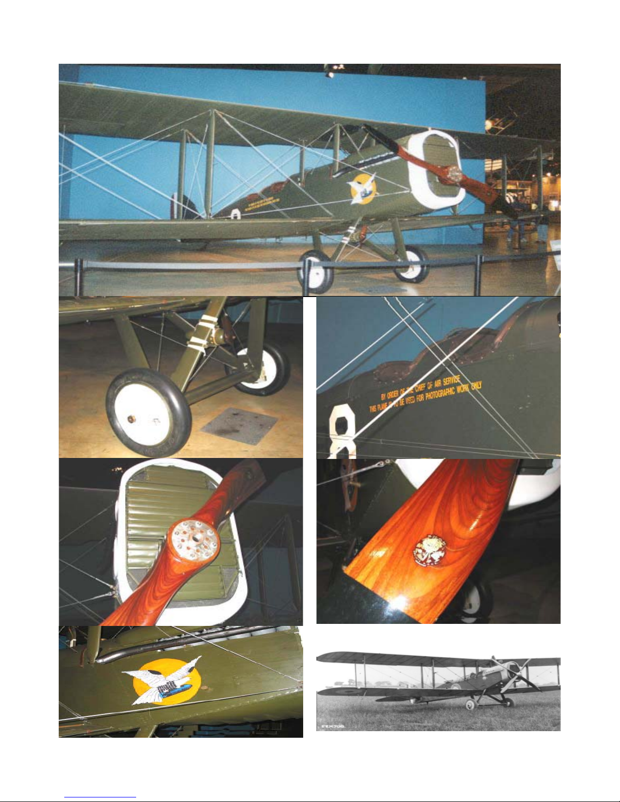
The de Havilland (Airco) D.H.4 (1916)
Generally accepted as being the best single engined day bomber
to serve with any of the combatants in World War I, the de
Havilland D.H.4 first flew as a prototype at Hendon in August
1916. Its flying qualities, speed and performance generally were
excellent, and were the basis of the success achieved by this
competent two-seater, 1,449 of which were subsequently built
in Britain.
The D.H.4 was a well designed and strongly built aeroplane,
and was fast enough to outrun all but the speediest German
Fighters. If it had a serious fault at all, this was probably the
unusually great distance between the front and rear cockpits,
which made communication between pilot and observer during
operations difficult if not actually impossible. This layout had
been adopted to give the pilot the best possible view downward
past the bottom wing for aiming the 460lb. of bombs which the
D.H.4 could carry.
The prototype had been powered by a 230 h.p. B.H.P. engine,
but it was decided to install the 250 h.p. Rolls-Royce Eagle in
production aircraft. However, a serious shortage of Rolls-Royce
engines led to some production batches being completed with
200 h.p. R.A.F.3a, 230 h.p. Puma or 260 h.p. Fiat A.12 engines.
D.H.4's in R.F.C. service were armed normally with a fixed,
synchronized forward gun for the pilot and one or two free-
firing Lewis guns in the observers's cockpit. Those with
R.N.A.S. squadrons had twin Vickers guns for the pilot and
could carry depth charges instead of bombs. Some R.N.A.S.
D.H.4's were later transferred to the R.F.C.
Two D.H.4's were experimentally fitted with 1 1/2 pounder
C.O.W. guns, firing upward through the center-section; these
were intended for attachikin Zepplins, but Germany suspended
airship raids on Britain and this version was not produced in
quantitty.
The other major wartime user of the D.h.4 was the American
Expeditionalry Force, for whom nearly 5,000 of these aircraft
were buitlt with 400 h.p. Liberty 12 engines; nearly 2,000 of
these reached France , and over 600 were in front line service
when the war ended. Apart from its career on the Western Front,
the D.H.4 also gave useful service in Italy, Msacedonia,
Mesopotamia, Palenstine and Russia.
Country of origin Great Britain
Purpose Bomber
Manufacturer Aircraft Manufacturing Co.
In operational use 1917/1918
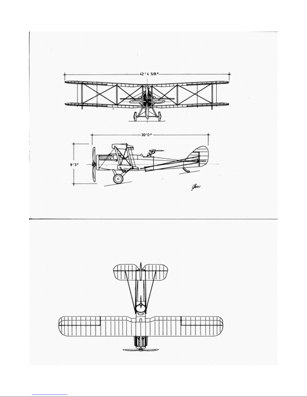
Brief Technical Details
Engine: 375 h.p. Rolls-Royce Eagle VIII
Wing Span: 42ft 4.63 in
Length: 30ft 8 in
Height: 10ft 0 in
Weight empty: 2,387 lbs Loaded 3,472 lbs
Max Speed: 143 m.p.h. at Sea Level
Ceiling: 22,000 ft
Range: 435 miles
Armament: One or two fixed, forward-firing Vickers and one or
two free-firing Lewis machine guns; plus 460lbs of bombs.
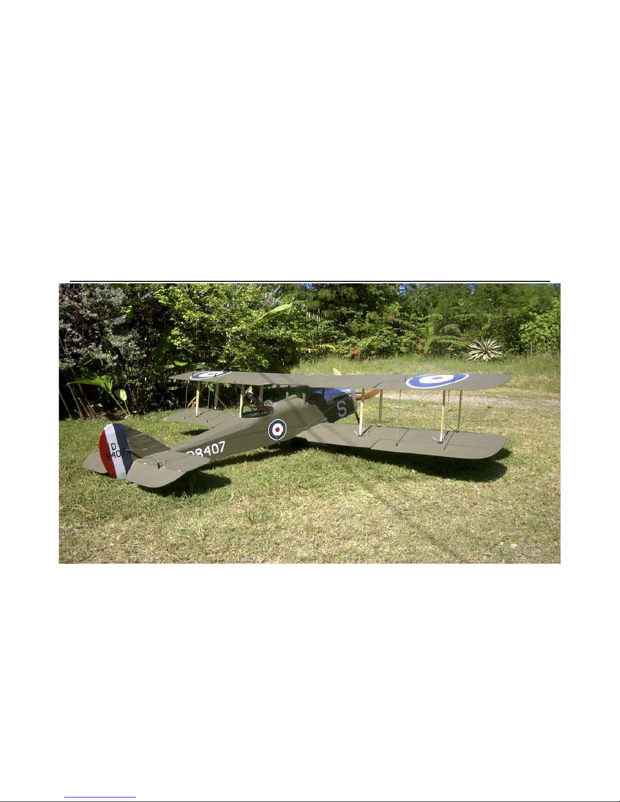
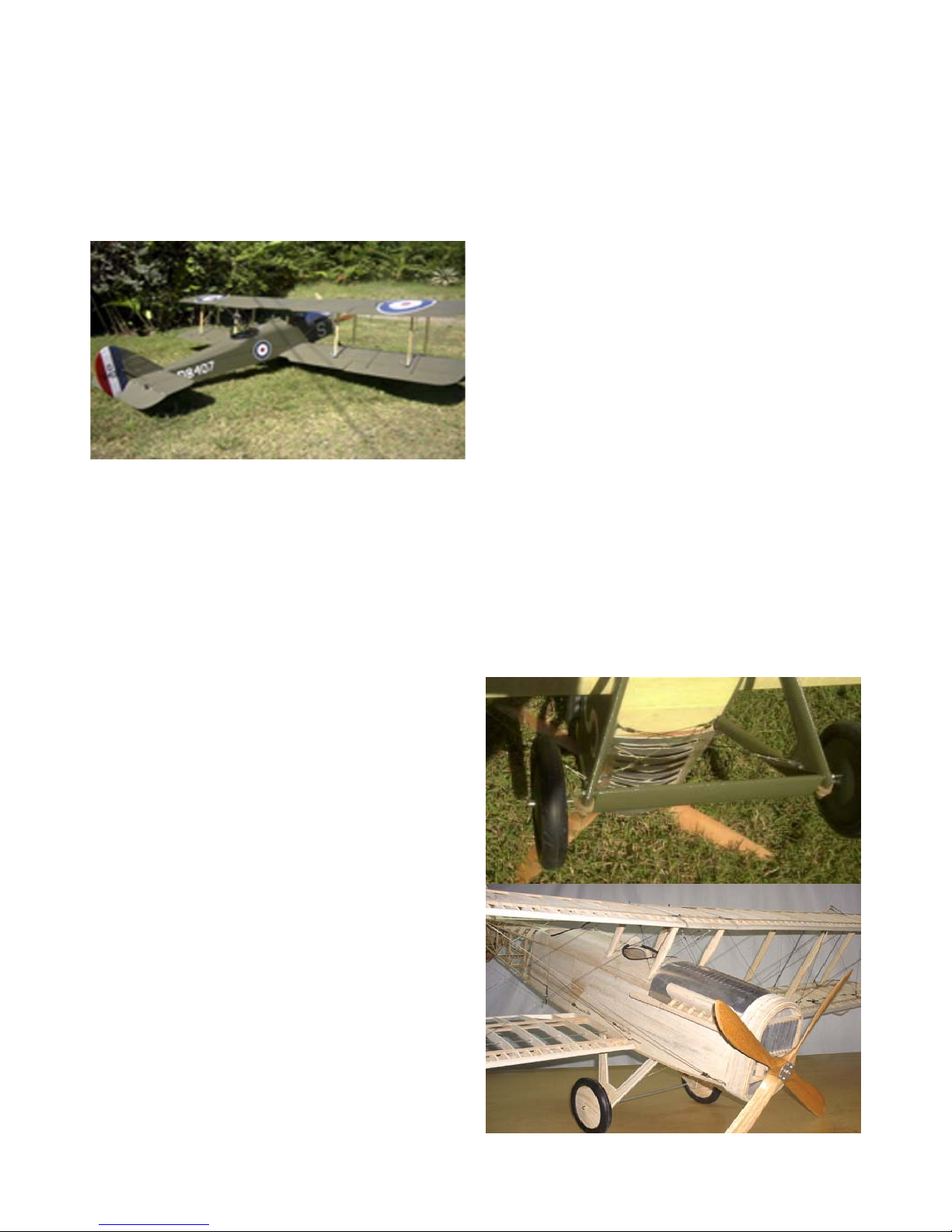
The Model
We have chosen the scale of 1:5 rendering a model
size that is easy to fly, but also relatively easy to transport.
Both the upper and the lower wing panels can be removed
for transport which gives very limited requirement for trans-
portation.
Rudder is controlled by pull-pull cables from the rud-
der bar and the elevator by a pull-pull bell crank coupled to
the control column in a scale manner. The tailskid is fully
functional but not stearable for ease of ground handling
(scale). Lower wing ailerons are controlled by pushrods from
one or two servos in the fuselage and the upper ailerons are
coupled to the lower with adjustable link rods.
The prototype was equipped with a Saito 1.20 4
cycle engine that gives ample power for this fighter. With
this engine the airplane is capable of some advanced
manoeuvers which you can demand from a WW1 biplane
fighter. The plane is a gentle flyer and it is recommended to
mix the rudder with the ailerons if you can.
Specifications:
Wingspan: 101.57” (258 cm)
Length: 51.6” (183 cm)
Wing area: 2588 sq" (167 dm²)
Weight: 16.2 lbs (7350 g)
Wing load: 14.4 oz/sq' (44 g/dm²)
Engine: 1.08 2-stroke -1.20 4-stroke
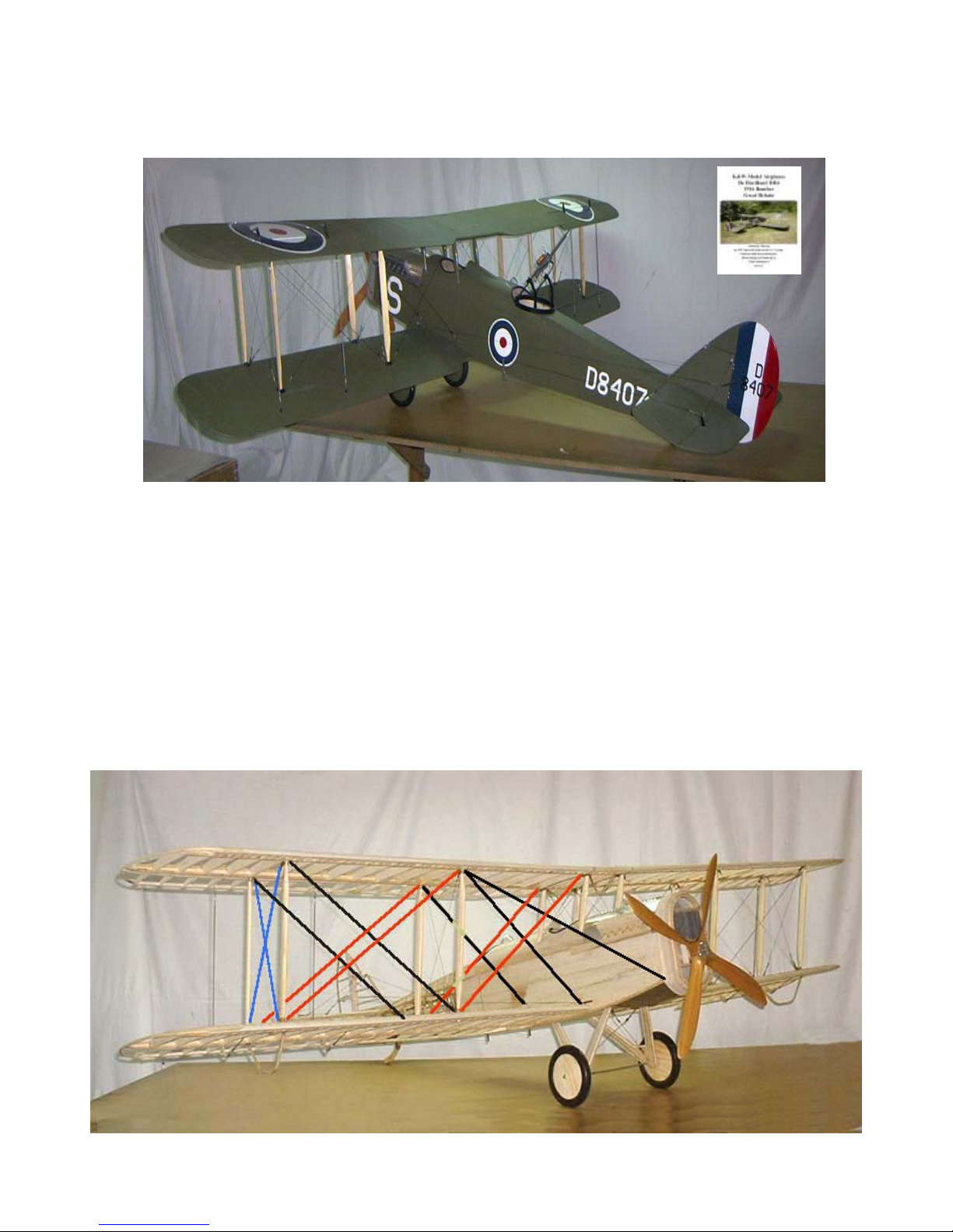
The K&W model of the DeHavilland D.H.4
Detail on Tail Group

de Haviland DH4B ARF 4
Covering and finish
The model is covered with Solartex and painted with
Dutch Boy enamel from the factory. When you have made
changes in the engine compartment, you will have to cover
the open areas with fuel proof paint.
The Assembled and Finished Model below
Color and markings
There are a number of survivors and we have cho-
sen to use the colour scheme and markings of the aircraft in
the Shuttleworth collection at Old Warden, Biggleswade,
England. Other schemes can be made on special request.
Ample documentation is available suggesting other colour
schemes and our model is rather neutral allowing several
attractive additions.
Installation of engine and Tank
We recommend that you don’t overpower this model.
The engine mounts have been installed for the recom-
mended size of engine. It may be necessary to introduce 2°
down and 2° right thrust of the engine. Either a 4 stroke or 2
stroke power plant will fit easily in the engine bay. However,
you must pay attention to engine cooling. We have provided
scale louvers in the top and bottom cowls. The engine bear-
ers are sufficiently strong to allow installation of ducts and
baffles as may be required. See photos.
1. Remove the aluminum cowling on top and bot-
tom.
2. Locate the engine and mark and drill the holes
for mounting.
3. The throttle servo can be installed in the engine
bay or behind the firewall. Use some scrap wood to fashion
a support for the throttle servo. Install the engine and con-
nect the throttle servo.
4. Make cut outs in the dummy manifold and or the
engine bearer platform to allow sufficient airstream around
the engine.
5. Reinstall the engine cowl using the #2 sheet metal
screws. The opening in the front of the radiator will provide
adequate area for the incoming cooling stream.
6. Install the tank in the available space with in the
engine bay.
Installation of servos, battery and receiver.
The aileron servo is installed in the lower part of
the servo vertical bulkhead under the rudder bar in the
fuselage. The elevator and the rudder servo are installed
in the servo tray. Battery pack and receiver are positioned
in the upper part of the tray. The switch can be mounted
on the servo tray with extension rod or on the instrument
panel.
1. Attach a ball link head to joystick and rudder
bar in the appropriate holes. You may have to enlarge the
holes to take the screw from the ball link. (Dubro #189 set
of 2).
2. Install the servos for rudder and elevator and
temporarily connect the servo arm's to the ball links. Neu-
tral position for the elevator is in line with the stabilizer.
Deflection for elevator is 20° up and down and for rudder
30° right and left.
4. Install the aileron servo in the bulkhead. The
aileron push rods attaches to the servo arm with adjust-
able clevices or ball links. Deflection of the ailerons should
be 20° up and down.
6. Install the radio switch on the dash board.
7. Place the receiver and the battery pack in the
upper part of the tray wrapped in foam rubber and secure
with rubber bands.
Photos of top and bottom enginePhotos of top and bottom engine
Photos of top and bottom engine
coco
coco
cowlingwling
wlingwling
wling

de Haviland DH4B ARF 5
Assembly of the DH4
All parts have been assembled at the factory and
only disassembled for transportation.
Rudder and wires are factory adjusted but may need
some tensioning adjustment after a while. For the elevator
a push rod is connected between the control column and
the bell cranks. The aileron pushrods are connected to one
or two servos in the bottom of the fuselage. Use ball links or
clevices for this connection as they have to be removed for
lower wing removal
Assembly of the Tail Unit
Assembly of wing panels
1. Install the lower wings by aligning the rods with
the holes in the fuselage and inserting fully.
2. Install the upper wing halves in the same man-
ner. Wing is attached to the center Cabane.
3. Install the interplane wing struts. The struts are
packaged in marked plastic bags. It is recommended that
you mark them individually after installation for ease of dis-
assembly. Connect the strut cross bracing by clipping the
kwick links in place.
4. Attach the landing and flying wires according to
the sketch on the last page of this manual. The wires have
all been precut and the plane was completely rigged at the
factory. So each wire should be at the correct length for
attachment..
5. Install the aileron interplane connecting rods.
6. In the fuselage, connect the aileron push rods to
the servo and check the throw of the ailerons (20° up and
down). For ease in control you may adjust the servo arms to
give differential throw in which case the up deflection should
be 30°.
7 Install the Lewis machinegun.
1. Fit the horizontal stabilizer to the fuselage with 3 nylon
screws.
2. Attach the rudder and vertical stabilizer assembly to the
top of the horizontal stabilizer, the rudder is held with a bracket
to the rear of the fuselage and below the stabilis along with a
screw (2mm X 13mm) at the front of the fin.
3. Secure the vertical and horizontal stabilizers with the sup-
port wires. Connect the elevator and rudder control lines.
.
4. Check the throw of rudder (30° right and left) and elevator
(20° up and down). Rudder is actuated by the rudder bar
and the elevator by the joystick.
Tail Detail

de Haviland DH4B ARF 6
Landing gear
Push the landing gear supports in the holes in the
fuselage. Secure with the landing gear cross bracing and
tighten.
Install the wheels on the shaft and secure with the
stoppers. Lace rubber bands in the fashion shown in the
sketch.
This is a very efficient shock absorber.
Flying characteristic is that of a biplane from the WW-
I period and it will fly happily on 3/4 throttle. Ground han-
dling on a hard surface demands a gentle hand but on
grass surface, the tailskid provides enough directional sta-
bility. During the initial take off run first keep full up eleva-
tor to keep the tail down. As the speed builds up, let go
gradually of the up elevator and the tail comes up. You
have to compensate for the torque with right rudder but
as the speed builds up the rudder is returned to neutral.
This model should fly of the ground and not be pulled.
Unlike many other planes from this period this type has a
lifting profile stabilizer that in theory should offset the climb-
ing tendency of the high lift wing profile. Once airborn the
aircraft is limited aerobatic like all biplanes from WW 1.
Remember that all turns are made using rudder and el-
evator and compensated with aileron!
The landing approach can be rather steep as per pro-
totype but the flare out needs almost full up elevator. Once
on the ground keep the tail down to maintain directional
stability. In case you have to make a dead stick landing,
keep the nose down and the speed up. The wires pro-
duce a lot of drag! It is always better to do a good landing
in a bad place than vice versa...
Happy landingsl
Lacing of
bungee
rubber
for the
wheel
shaft
Balancing
The C/G (center of gravity) or balancing point should be no
further back than approx. 13,5 cm (5½”) measured from the
center of the leading edge on the upper wing. Make adjust-
ments by adding wheight if necessary. If you desire a more
groovy and stable flight performance you may move the C/
G as much as 1" (2.5cm) forward.
Flying
Let the engine swing a 14"x6" propeller if possible. This
gives better thrust outside the big radiator front and reduces
sound to a more realistic level.

de Haviland DH4B ARF 7

de Haviland DH4B ARF 8
DeHavilland DH4 in Three View

de Haviland DH4B ARF 9
What is in the box:
The ARF kit contains the parts shown in the picture.
All the parts are covered and painted. All the rigging
wires are supplied in the correct lengths and need
only to be clipped to their positions.
1. Fuselage with wing cabane, detachable landing gear.
2. Scale wheels
3. Fuselage mounted Vickers machinegun
4. Scale propeller
5. Fin / rudder
6. Tail skid.
7. Stabilizer / elevator
13
1
2
5
6
7
11
8
10
12
11
8. Upper wing panels
9. Lower wing panels
10. Interplane struts
11. Aileron connecting rods
12. Wires, turnbuckles and hardware
13. Assembly manual
11
9
6
10
4
Rigging Details
1. All rigging wires are precut to length with quick links attached.
2. Connect cross brace wires, colored Blue in photo.
3. Connect Flying Wires, colored Black in photo.
4. Connect Landing Wires, Colored Red in photo.
23
4

de Haviland DH4B ARF 10
P.O.Box 1229, Cebu City Centrl. Postoffice
Cebu City 6000, Philippines
Visiting address:
3343 Gun-Ob, Kinalumsan,
Lapu-Lapu City 6015, PHILIPPINES
Phone +63 32-340 0772, Cellular +63 917-3200 985
Website http://www.kwmairpl.com.ph
K&W
Model
Airplanes Inc.
Table of contents
Other K&W Model Airplanes Toy manuals
Popular Toy manuals by other brands

Rail King
Rail King DASH-8 DIESEL ENGINE operating instructions

Canon
Canon CREATIVE PARK Reindeer Assembly instructions

LEGO
LEGO 70404 Building instructions

Fisher-Price
Fisher-Price CATERPILLAR 73260 Owner's manual & assembly instructions

Hasbro
Hasbro ZOIDS BERSERK FURY instructions

Premier Kites
Premier Kites Mesh French Rear Top Assembly instructions

Dancing Wings Hobby
Dancing Wings Hobby 1.8M 1:5 Savage Bobber instruction manual

Tiger Electronics
Tiger Electronics Neopets Shoyru Pen 70122/70121 instructions

Mattel
Mattel Barbie DMC30 instructions

Fisher-Price
Fisher-Price Little People HJL86 manual

le-idea
le-idea IDEA10 quick start guide

MSH
MSH Protos Carbon instruction manual