manuals.online logo
Brands
  1. Home
  2. •
  3. Brands
  4. •
  5. K&W Model Airplanes
  6. •
  7. Toy
  8. •
  9. K&W Model Airplanes Bristol F2-B 1917 Fighter User manual

K&W Model Airplanes Bristol F2-B 1917 Fighter User manual

Other K&W Model Airplanes Toy manuals

K&W Model Airplanes De Havilland DH4 1916 Bomber User manual

K&W Model Airplanes

K&W Model Airplanes De Havilland DH4 1916 Bomber User manual

K&W Model Airplanes Fokker E-III User manual

K&W Model Airplanes

K&W Model Airplanes Fokker E-III User manual

Popular Toy manuals by other brands

FUTABA GY470 instruction manual

FUTABA

FUTABA GY470 instruction manual

LEGO 41116 manual

LEGO

LEGO 41116 manual

Fisher-Price ColorMe Flowerz Bouquet Maker P9692 instruction sheet

Fisher-Price

Fisher-Price ColorMe Flowerz Bouquet Maker P9692 instruction sheet

Little Tikes LITTLE HANDIWORKER 0920 Assembly instructions

Little Tikes

Little Tikes LITTLE HANDIWORKER 0920 Assembly instructions

Eduard EF-2000 Two-seater exterior Assembly instructions

Eduard

Eduard EF-2000 Two-seater exterior Assembly instructions

USA Trains EXTENDED VISION CABOOSE instructions

USA Trains

USA Trains EXTENDED VISION CABOOSE instructions

Modellbau Laffont Z1601 Assembly instructions

Modellbau Laffont

Modellbau Laffont Z1601 Assembly instructions

NOCH 12905 instruction manual

NOCH

NOCH 12905 instruction manual

Eduard Ki-61-Id quick start guide

Eduard

Eduard Ki-61-Id quick start guide

Viessmann Vollmer 45616 Mounting instruction

Viessmann

Viessmann Vollmer 45616 Mounting instruction

Vollmer 42004 Mounting instruction

Vollmer

Vollmer 42004 Mounting instruction

Phoenix Model CLASSIC-EP instruction manual

Phoenix Model

Phoenix Model CLASSIC-EP instruction manual

H-KING Sopwith Camel British WW1 Fighter instruction manual

H-KING

H-KING Sopwith Camel British WW1 Fighter instruction manual

MODSTER Predator 4x4 Crawler user manual

MODSTER

MODSTER Predator 4x4 Crawler user manual

DHK Hobby 8136 User instruction manual

DHK Hobby

DHK Hobby 8136 User instruction manual

THUNDER TIGER Raptor 50 V2 kit manual

THUNDER TIGER

THUNDER TIGER Raptor 50 V2 kit manual

Timberkits Skateboarder instructions

Timberkits

Timberkits Skateboarder instructions

Hangar 9 Funtana 125 Assembly manual

Hangar 9

Hangar 9 Funtana 125 Assembly manual

manuals.online logo
manuals.online logoBrands
  • About & Mission
  • Contact us
  • Privacy Policy
  • Terms and Conditions

Copyright 2025 Manuals.Online. All Rights Reserved.

Bristol F2B Fighter ARF
1
Assembly Manual
for ARF stand-off scale model in 1:5 scale.
Historical data and presentation.
Model design and construction drawing
by Göran Kalderén ©
Revised 2000-09-05
Bristol F2-B
1917 Fighter
Bristol F2B Fighter ARF
2
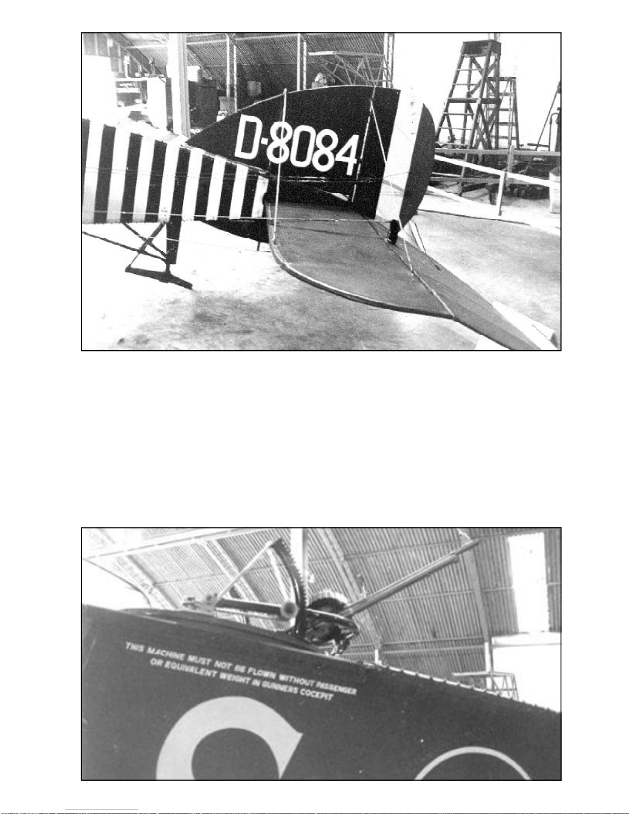
Theaircraftwasarmedwithasinglesyn-
chronized .303 Vickers machine gun with 963
rounds of ammunition in the nose for the pilot
and a .303 Lewis machine gun for the observer
with seven 97 round ammunition drums. Some
aircraft were upgunned in the field with an addi-
tional Lewis gun mounted over the wing to aug-
menttheforwardfirepowerand twin Lewis guns
in the rear cockpit mounted on a Scarff ring.
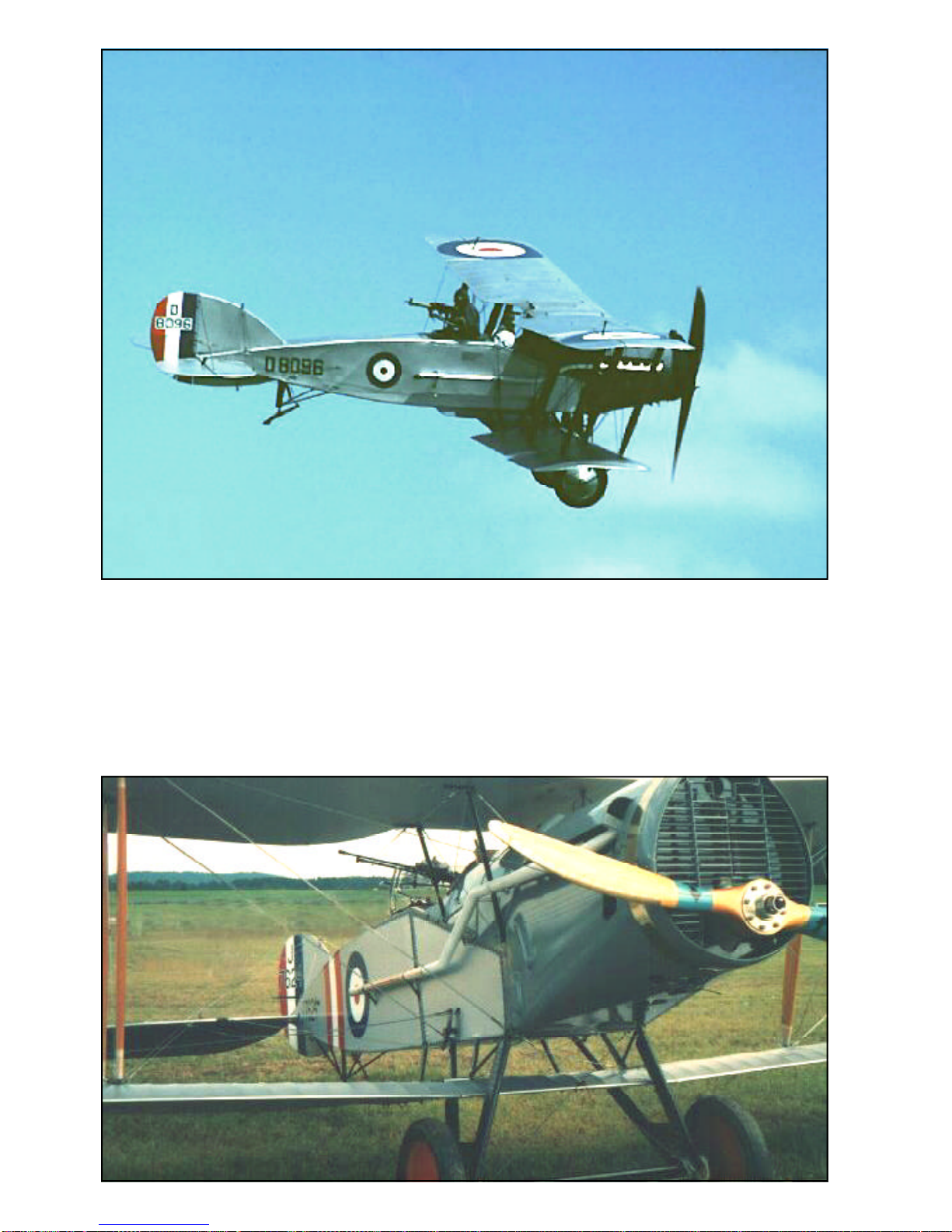
TheincreasedproductionrateatBristol’s
for the F2B resulted in a shortage of engines
sinceRolls-Roycewasunableto keep pace with
the demand for Falcon engines As a result, al-
ternative engines were examined and tested;
includingtheSiddeleyPuma,Hispano-Suiza200
hp. Hispano-Suiza 300 hp and the 200 hp Sun-
beam Arab. The Sunbeam Arab being finally
chosen, although others continued to be tested
since the Arab equipped variants proved
to be somewhat under-powered. The installa-
tionoftheArabenginealteredthenosecontours
andexhaust stackarrangement.
Before the end of the First World War,
the Bristol fighter was to see service in various
theatersofwar,including with No 139inItaly and
No67 (Australian) Squadron in the Middle East
Nos. 33, 36, 39, 76 and 141 Squadrons used
Bristol Fighters for home defense duties.
F2Bsusedbyhomedefenseunits as night fight-
ers were modified in a number of ways. Some
were fitted with navigation lights on the lower
wing tips and rudders, Holt flare brackets be-
neath each lower wing tip and illuminated gun
sights.Othernight fighters werefitted with addi-
tional forward firing machine guns. One aircraft
ofNo39HomeDefenseSquadronhadtwoLewis
gunsfitted over thewing in addition to itsnormal
single Vickers gun and twin Lewis guns for the
observer.
ByNovember of1918 over5,500 Bristol
fighters,mainly F2Bs, had been orderedand, of
these, 3,101 had been taken into the RFC and
RAF. Although the Armistice led to cancellation
of some orders, the “Biff” as it was known to
wartime airmen, continued to be manufactured
until September of 1919, with a total of 4,747
beingproduced.
Documentation is available in Bristol Fighter
inAction,Aircraft#137bySquadron/signalPub-
lications Inc., 1115 Crowley Drive, Carrolltown,
Texas75011-5010,USA,ISBN-0-89747-301-9.
Bristol Fighter by JM Bruce, Albatros Produc-
tionsLtd.,10 Long view,Berkhamsted, Herford-
shire,HP41BY,GreatBritain.ISBN-0-948414-85-5.
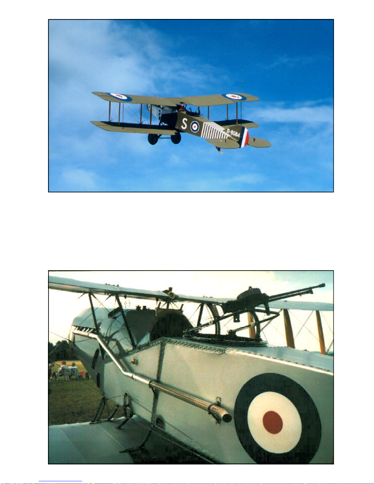
Bristol Fighter F2B
For the British aircommand it became
in1916 obvious thata replacement forthe slow
andvulnerable BE2 series of aircraft was badly
needed. Bristol at this time had designed a 2
seater airplane of girder box design. To over-
comethe restricted forwardview for thepilot the
upper wing was placed only 1 foot above the
fuselage.The pilot’s line of sightwas obstructed
only by the mere airfoil section thus rendering
goodvisibility forward/upwardandforwarddown-
ward. The necessary distance between wing
planes was obtained by moving the lower wing
downwardunder the fuselage.The first produc-
tion aircraft were designated F2A but when put
in service as a reconnaissance aircraft, the old
tactics were used and the plane became easy
preyfortheopponents.
A revised model F2B fighter/recon-
naissance with improved 275 hp. Rolls-Royce
Falcon engine and fighter tactics applied, be-
cameatremendous success. Thisengine is liq-
uidcooledandtheradiatorfirst deployed as side
mounted, soon was changed and located up
front giving the nose a characteristic outline.
Thearmament was a Vickers .303machine gun
mountedunder the hoodand shooting synchro-
nized to fire through the propeller arc through a
roundoutlet in theupper part of the radiator.For
the observer there was a Lewis machine gun
mounted on a Scarff ring mount.
As production increased during 1917 it
became difficult for Roll-Royce to keep up with
demandandotherengine alternatives were tried
andemployed.
That this was a very successful aircraft
type shows in that more than 4700 aircraft were
producedandthatthatproductioncontinuedlong
afterthewar had ended. Theaircraftsaw action
in many foreign countries and was used by the
British in their overseas operations.
As production of the F2B increased in
speed during the mid-Summer of 1917, addi-
tional Royal Flying Corps squadrons were
formed or re-equipped with the new Bristol
fighter. The production F2B featured a reduced
chordtailplanewithlongerspanelevators.These
were later changed to use the elevators of the
F2Awiththe tail plane ofthe F2B and thisarran-
gement was retained for all wartime F2Bs.
The F2B benefited from the lessons
learned from the first combat use of the F2A
variants.When introducedin combatthey were
flown in action using single seat fighter tactics,
which immediately proved successful.
Bristol F2B Fighter ARF
3
Bristol F2B
Fighter
1917
Specification:
Wingspan, 39' 3" (11,96 m.)
Length, 25' 10" (7,87 m.)
Heigth, 9' 9" (2,97 m.)
Engine, 275 hp Rolls Royce Falcon III
liquid cooled.
Armament, 1 Vickers .303
forward firing syncronized
machine gun, 1 Lewis on
Scarf ring mount in rear
cockpit
Speed, 113 mph., (182 kph)
Service ceiling, 20,000 feet
Crew, 2
Bristol F2B Fighter ARF
4
Bristol F2B Fighter ARF
5
Bristol F2B Fighter and Canadian pilots
The Canadian Air Force only ever held two ”Brisfits”
or ”Bifs” on strength from 6 August, 1920 to 7 Feb-
ruary, 1922 as part of an Imperial Gift of 114 varied
aircraft,however Canadian airmenflew the two-seat
fighters in the service of the Royal Flying Corps as
well as the CAF during the First World War. Cana-
dian Air Service pilot Lt. A.E. McKeever of No. 11
Squadron soon began to be regarded as an ace
amongBristolFighter exponents, and between him-
self and his regular observer, Sgt. (later Lt.) L.F.
Powell accounted for 28 aircraft from the time of
their first victory on 26 June, 1917 and the end of
the year. With the formation of No. 1 Squadron,
Canadian Air Force, McKeever was appointed its
commanding officer and he adopted the Bristol
Fighter as his personal aircraft. This machine later
went with him when he returned to Canada after the
Armistice and was later registered on the Canadian
Civil Registry as G-CYBC.
Bristol F2B Fighter ARF
6
Our model depicts the Bristol F2b D8084, No.139
Sqn RAF Villaverla Aerodrome in September 1918.
Originally formed in March 1918 as ’Z’ Flight and
attached to No.34 Sqn in Italy for long range recon-
naissance duties. By July 1918 a second flight had
arrivedandthe combined unit was knownas No.139
Sqn RAF. The original marking of two vertical white
bands soon gave way to four white and three black
bands and ultimately expanded to the 12 and 11
depicted on D8084 as it is presently painted. This
aircraftalsocarried a spanwise w/b/wstripe between
the upperwing. The pictures on this page are the
Bristol F2b Fighter of the Shuttlewort Collection in
the air above Old Warden Aerodrome, England.
Below the same aircraft on the ground at Old War-
den, Biggleswade.The paintwork shown is the post
war service, and prior to 1981 when the aircraft was
rendered the original camouflage and markings.
Bristol F2B Fighter ARF
7
The Bristol F2B Fighter, that we have modeled, is
the aircraft that is kept in flying condition by the
Shuttleworth Collection in England. These pictures
show details of the aircraft as it looks today. The
front cowling plates have been removed for service
and reveal the powerful 12 cylinder Rolls Royce en-
gine as well as the areas adjacent to the cockpit.
The paint scheme was changed in 1981, when the
aircraft was completely overhauled, and is now rel-
evant to the period at the end of the war. The serial
number has been placed on the fin and the aft sec-
tion has white stripes across the sides and upper
surfaceofthefuselage.The alloverpaintcolorisPC10
(we use olive drab which is like sun bleached PC10)
onall uppersurfaces andnaturallinen offwhite onthe
under surfaces. Above the large identification letter
”S”isa instruction and warning notto fly without gun-
ner/observerorequivalent weight in therear cockpit.
The model that we have depicted in this manual has
since been repainted and shows now the accurate
scheme.
All pictures on this pages, courtesy of Shuttle-
worth Collection, Old Warden Aerodrome,
Biggleswade, Befordshire SG18 9EP, England.
Bristol F2B Fighter ARF
8
The impressive Rolls Royce Falcon III 275 Hp 12
cylinder liquid cooled V-engine.
The picture below shows also the spent cartridge
chute and the rear part of the Vickers machine gun.
Bristol F2B Fighter ARF
9
The Model
We have chosen the scale of 1:5 that
givesa modelwiththewingspanofalmost8feet.
This in turn is a rather large aircraft but the han-
dling in the air is very satisfactory.
Fortransport to and from theflying field,
bothwingpanelgroupscan be removed, rigged
and complete, with only the disconnection of a
fewriggingwires4lockingscrews and the servo
connectors. All the settings and trims are pre-
served. As per prototype, the elevator can be
trimmed for angle of incidence. All the rigging
wiresare functional andaid to the stability ofthe
airplane. As additional feature, you can have a
functional exhaust manifold, connected to your
4 stroke engine and displacing the exhaust in a
scale manner.
Thereisampleroom for radioequipment,
servos and extras that you would want to add.
For ease of ground handling, the tailskid is
stearable and coupled to the rudder bar with
wires. Thedocumentation referstotheaircraft,
still today in flyable condition in the Shuttlewort
Collection in England. The scale propeller deliv-
ered with the model is 2-bladed but a 4-bladed
can be supplied as extra item on request.
Thefinishedmodelispainted in 1918 livery
and further detailing can be made as per
documentation.
Specification
Wingspan 94" (239 cm)
Length 62" (157 cm)
Wing area 243 sq. inch 157(dm²)
Weight 18 lb. (7900g)
Wing Load (50 g/dm²)
Engine .90 - 1.20 (15 - 20cc) 4-stroke
Covering and finish
The model is covered and painted on the
outside from the factory. You should cover the
engine compartment with fuel proof paint after
adjustments and installation of the engine. We
use Solartex Antique and Olive drab covering
materialandmatchingDutchBoyEnamelpaints.
Installation of engine.
We recommend that you don’t overpower
thismodel. Itwill flyhappily witha 1.204-stroke
engine. Our prototype was tried with a OS 1.20
4- stroke, which gave ample thrust. The engine
mounts have been installed for this size of
engine. The access to the glow plug is difficult
so we recommend an extension and you can
placetheconnector in the holeon the left sideof
the cowling.
1. Adjust the width of the engine mounts if
necessary, and drill the holes for the engine.
Insertblindnuts to takethe engine bolts.
2.Install the 16 Oz tank on the right side in
the engine compartment. Connect the required
silicon tubing.
3.Installtheengine and connectthethrottle
servo.
Installation of servos, tank, battery and
receiver.
The aileron servos are installed in the
wing root of the lower wing panels. A Y-cable
leadsup to the receiver. Werecommend Dubro
# 121 E/Z connector for these servos.
The throttle servo is installed upright in
the servo tray.
The elevator servo and the rudder servo
areinstalled inverted in the tray.
Battery pack and receiver are positioned
intheuppertray.
The switch is mounted on or under the in-
strument panel.
To access the servo tray and receiver tray
forinstallationofthe servos receiverandbattery
packyou willhavetoremovetheupperandlower
center wing sections. Beginning with the lower
wingsection you willhave to removethe landing
gear. Release the cross bracing wires for the
landing gear and pull the legs straight out.
Removethe 4pcs 6-32Allen screwsand liftout
the lower wing section. Open and remove the
hatch by removing the #2 sheet metal screws.
The upper tray is accessible by removing
Typical servo installation
Bristol F2B Fighter ARF
10
30 mm.
1.5 mm.
Complete "turnbuckle" assembly
Typical fashion
of lacing bungee
rubber cord.
the upper center section (4 Allen 6-32 screws.
Either one of the 2 aluminum panels can now
be removed by unscrewing the sheet metal
screws. Note that different length of screws
have been used for the various locations. The
rubber coaming can be removed and later
replacedwithout using glue.The center section
ishelddown by thewindscreen , whichcan after
removing one screw be swung to the side
releasing the panel.
1. Attach a clevis or ball link head to joy-
stickandrudderbarintheappropriateholes.You
mayhaveto enlarge theholes to takethe screw
from the ball link (Dubro #189 set of 2).
2.Installtheservosfor rudder and elevator
and connect the servo arms to the clevices or
ball links. Deflection for elevator is 20° up and
downand for rudder 30° right and left.
3. Install and connect the throttle servo in
thefashionyouprefer.
4. Install the tank in the available space at
the right side of the engine compartment.
5.Installtheaileronservosin the wing root.
Thehatchcoveris secured with4#2sheetmetal
screws. The aileron connecting rods attaches
totheservoarm. Differential throwontheaileron
is recommended Deflection of the ailerons
shouldbe 25° up and 15°down.
6.Installtheswitchon the instrument panel.
7. Place the receiver and the battery pack
in the upper part of the tray, wrapped in foam
rubber and secure with rubber bands.
Assembly of the Bristol F2B Fighter
All parts have been assembled at the
factoryand onlydisassembledfortransportation.
Rudder and elevator wires are factory
adjusted but may need some tensioning
adjustmentafterawhile.Aileronsareadjustable
with the clevises to the connecting rod and to
theaileron horn.
Assembly of the tail unit
1. Secure the top and the bottom fins with
the brackets using #2 sheet metal screws. The
rudder is permanently attached to the fins.
2. Pushthestabilizer with elevators onthe
brass tubes in the fuselage. Connect the sup-
porting wires with clips in their respective
positions.See riggingsketch.
3. Connect the elevator wires. Note that
these wires are crossed.
4. Connect the rudder wires. The wires for
the stearable tailskid are installed from the
factory.
Assembly of wing panels
Flying- and drag-wires are 90 lb. breaking
strength, all other wires are 40 lb. breaking
strength.
1.Pushthelowerwinghalvesintotheholes
inthelower wing center sectionandconnect the
servo leads to the Y-cable.
2. Push the upper wing halves into the
holesinthe upper wingcenter section. Connect
theflyingwiresandthelanding wires. Start with
thelanding wires thatare attached tothe upper
wing cabanes. Insert the inner pair of the
interplane struts (the forward is shorter).
3. Now connect the flying wires to this
interplane strut pair. Proceed with the next bay
repeating the procedure.
4.Whenallstrutshavebeeninstalled, you
can connect the X-bracing for the interplane
struts.
5. Last the drag wire are attached to the
fuselage at the fitting behind the radiator.
6. When both wings sets have been
assembledyouwillhaveto connect the ailerons
with the interconnecting rod. This has clevises
in both ends to ease assembly. Check that the
distance is correct and adjust if necessary. The
ailerons must be parallel on both wing halves.
7. Lock the wing halves in position with the
four#2sheetmetalscrews.Thetabsareaffixed
to the wing sections.
8.Checkthedihedral.Itshould be 2.5" /6,5
cm measured at each tip of the lover wings. If
necessary you can adjust the dihedral by tight-
eningandlooseningtheflying-andlandingwires.
Youneednottouchtheinterplanecrossbracing.
Disconnect the wires and start adjustment with