Kangaroo Sydney User manual

SEW IN COMFORT. SEW LONGER.™
ASSEMBLY INSTRUCTIONS
Sydney
ITEM NO.: K4711 EL Ash White Electric Lift
K4711 XL Ash White Hydraulic Lift

Assembly InstructionsSydney XL 2
1. Read the instructions carefully before beginning the assembly process to ensure proper assembly
of this product. Please open and inspect the contents of box(es) to see that all parts and hardware
are included.
2. Tools Required
180°
Screw cam bolts flush as
illustrated.
Press cam into hole until flush with
surface. The arrow direction must
be in the direction of the hole.
Insert bolt through pre-drilled
hole in edge of panel.
Turn clockwise to lock cam with bolt.
General Assembly Guidelines
3. Understanding How the Cam Fastener Works
Tip: place a small bit of WD-40 or similar
lubricant into the pre-installed cam bolt
holes to help the cam bolts screw in better.
4. Glue provided is to secure wood dowels in place and is optional. If glue is used during assembly,
locate the appropriate hole for the dowel, place a small amount of glue in the hole and insert the
dowel. Wipe away excess glue immediately. It is not necessary to glue the other end of the dowel
when attaching to other parts.
Use and Care Your cabinet normally requires a minimum amount of maintenance; however, the
following points are worth noting:
Cleaning – To remove marks and enhance the surface, wipe with a gentle all-purpose cleanser. DO NOT
use ammonia-based, harsh chemicals or abrasive cleaning agents. Wipe dry immediately.
Electrical and Hydraulic Lifts – Require annual lubrication with WD-40 or similar lubricant.
Phillips Screwdriver Hammer Electric Screwdriver
Torque set to 3-5

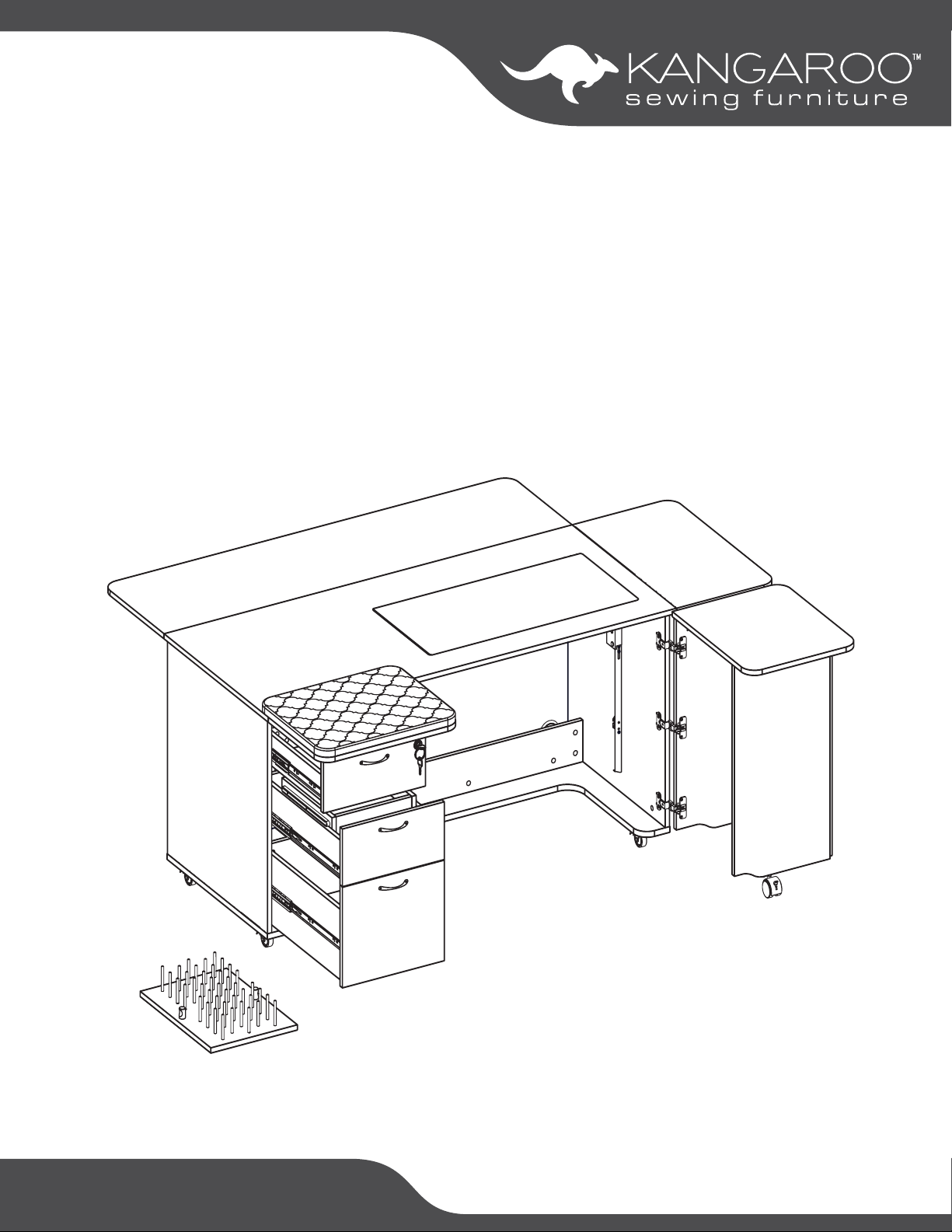
Assembly InstructionsSydney XL 3
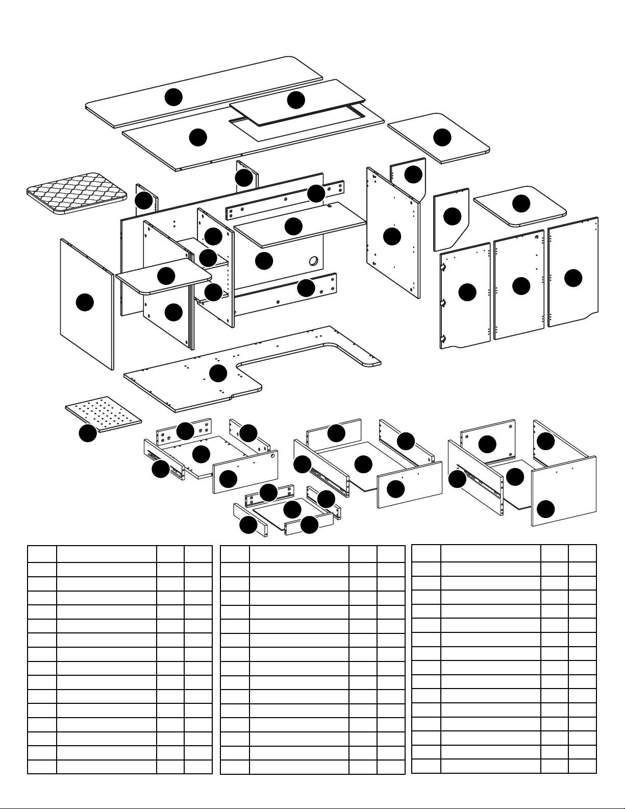
Parts List: Panels
A
X
Y1
Z
Y2
V1
V2
V3
O1
O2
O3
04
O5
O6
D
G
A3
A2
A4
B
A1
A5
O8
K1
K2
K3
K4
E
E
L
K6
L2
L3
L1
K7
K8
K9
K5
L4
L4
L5
L5
ITEM DESCRIPTION QT Y. BOX
Hardware Box 1 1 of 5
L6 Drawer Insert Tray Bottom 1 1 of 5
EShelves 2 1 of 5
K1 Top Drawer Front 1 1 of 5
K2 Middle Drawer Front 1 1 of 5
K3 Top Drawer Back 1 1 of 5
K4 Top Drawer Left Side 1 1 of 5
K5 Top Drawer Right Side 1 1 of 5
K6 Top Drawer Bottom 1 1 of 5
K7 Middle Drawer Back 1 1 of 5
K8 Middle Drawer Left Side 1 1 of 5
K9 Middle Drawer Right Side 1 1 of 5
LBottom Drawer Front 1 1 of 5
L1 Bottom Drawer Back 1 1 of 5
L2 Bottom Drawer Left Side 1 1 of 5
ITEM DESCRIPTION QT Y. BOX
L3 Bottom Drawer Right Side 1 1 of 5
XLeft Panel 1 1 of 5
Y1 Left Center Panel 1 1 of 5
A2 Right Side Leaf 1 2 of 5
DBack Panel 1 2 of 5
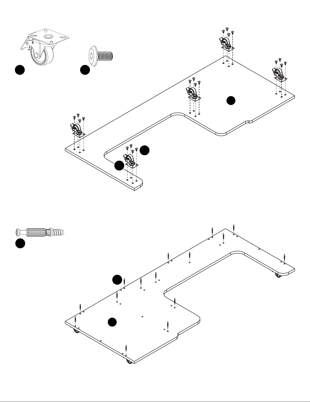
GBottom Panel 1 2 of 5
BLift Platform 1 3 of 5
L4 Drawer Insert Tray Sides 2 3 of 5
L5 Drawer Insert Tray Front/Back 2 3 of 5
L7 Large Drawer Bottoms 2 3 of 5
O1 Right Quilt Leaf Support 1 3 of 5
O2 Left Quilt Leaf Support 1 3 of 5
V1 Door Panel 1 1 3 of 5
V2 Door Panel 2 1 3 of 5
V3 Door Panel 3 1 3 of 5
ITEM DESCRIPTION QT Y. BOX
Ironing Pad 4 of 5
A3 Drawer Cover Panel 1 4 of 5
A4 Door Tabletop Panel 1 4 of 5
O3 Right Side Leaf Support 1 4 of 5
O4 Left Side Leaf Support 1 4 of 5
O8 Thread Spool Holder Panel 1 4 of 5
Metal Support Bar 1 5 of 5
ATop Panel 1 5 of 5
A1 Rear Quilt Leaf 1 5 of 5
A5 Sewing Well Cover Panel 1 5 of 5
O5 Lower Support Panel 1 5 of 5
O6 Upper Support Panel 1 5 of 5
Y2 Right Center Panel 1 5 of 5
ZRight Panel 1 5 of 5
04 NOT SHOWN: Electric Lift Support 1
L7
L7
L6

Assembly InstructionsSydney XL 4
Parts List: Hardware
TIP: Keep all the parts in their individually labeled bags. This will make finding parts easier as you assemble your cabinet.
Locking Plate Caster x5
t2
8x16 Fix Bolt x20
b1
6x35 Cam Bolt x82
c1
8x30 Dowel Pin x58
d1
Lift Rail
(Left) x1
Lift Rail
(Right) x1
3.5x14 Screw x170
s1
5⁄8“ Cam Cover x82
c2
Lock x1
Lock Plate x1
Key x2
L
Butt Hinge x20
h3
Alignment Pin x4
s5
Magnet x7
Catch Plate x7
m
Locking Caster x4
t1
Hinge Body x3
g1
3.5x20 Screw x10
s4
Handle x4
h
4x20 Fix Bolt x10
b2
3M Clear Adhesive
Panel Protector x4
3.5x30 Screw x12
s6
Peg x8
p1
Flap Hinge x2
h4
3x14 Screw x14
s2
Threaded
Dowel Pin x3
p
6x50 Dowel Pin x41
d2
Knob x2
h1
Cam Lock
Pre-installed parts
Caster Bracket
c5
Snag Free Hinge
h4
Stabilizing Foot for
O4 Panel (EL model only) x2
s7
Allen Wrench x1
a
14mm Wrench x1
r3
Adhesive Foam Sheet x1
Drawer Insert Runners x2
Lock x1
Key x2
L2
Metal Support Bar x1
Folding Hook x2
h2
Lift x1

Assembly InstructionsSydney XL 5
Step 1: Cabinet Shell
Locking Plate Caster x5
t2
8x16 Fix Bolt x20
b1
6x35 Cam Bolt x15
c1
G
G
b1
t2
c1
Attach t2 Plate Casters to the underside of Panel Gwith b1 Fix
Bolts.
Tighten with provided Allen Wrench.
Lock the Casters and flip Panel G over.
Install c1 Cam Bolts on Panel G.

Assembly InstructionsSydney XL 6
Step 1: Cabinet Shell
X
Y1
Y2
6x35 Cam Bolt x4
c1
8x30 Dowel Pin x16
d1
Lift Rail
(Left) x1
3.5x14 Screw x3
s1
c1
c1
d1
d1
d1
s1
Install 2 c1 Cam Bolts
and 4 d1 Dowel Pins in Panel X.
Install 6 d1 Dowel Pins in
Panel Y1.
Attach Left Lift Rail to
Panel Y2 with s1 Screws.
Install 2 c1 Cam Bolts
and 6 d1 Dowel Pins in Panel Y2.

Assembly InstructionsSydney XL 7
Step 1: Cabinet Shell
Z
D
6x35 Cam Bolt x8
c1
8x30 Dowel Pin x18
d1
Lift Rail
(Right) x1
3.5x14 Screw x3
s1
c1
c1
d1
d1
s1
Install 4 c1 Cam Bolts
and 6 d1 Dowel Pins in Panel Z.
Attach Right Lift Rail to
Panel Z with s1 Screws.
Install 4 c1 Cam Bolts
and 12 d1 Dowel Pins in Panel D.

Assembly InstructionsSydney XL 8
Step 1: Cabinet Shell
8x30 Dowel Pin x4
d1
d1
O5
O6
Y2
O5
O6
5⁄8“ Cam Cover x4
c2
Install 2 d1 Dowel Pins in Panel O6.
Install 2 d1 Dowel Pins in Panel O5.
Attach Panels O6 and O5 to Panel Y2.
Tighten cam locks and apply cam covers.

Assembly InstructionsSydney XL 9
Step 1: Cabinet Shell
5⁄8“ Cam Cover x2
c2
D
O5
O6
Y2
NOTE: The illustrations shown through Page 11 show upside down assembly.
Assembling these panels upside down will make attaching the bottom
(Panel G) easier.
Once the bottom is attached, you will flip the cabinet over.
You may need a second person to help you.
Attach Panel Y2 to Panel D as shown.
Tighten Cam Locks and apply Cam Covers.

Assembly InstructionsSydney XL 10
Step 1: Cabinet Shell
5⁄8“ Cam Cover x8
c2
Z
D
O6
O5
X
D
Y1
Assemble Panels Z, D and X
as shown here.
Tighten Cam Locks and
apply Cam Covers.
Attach Panel Y1 to Panel D as shown here.
Tighten Cam Locks and apply Cam Covers.

Assembly InstructionsSydney XL 11
Step 1: Cabinet Shell
5⁄8“ Cam Cover x15
c2
G
Z
D
Y2
Y1
X
O5
Attach Panel G as
shown, carefully lining
up Cam Bolts in Panel
G with Cam Locks on
Panels Z, D, O5, Y2,
Y1 and X.
You may need a second
person to help you.
Tighten Cam Locks
and cover with Cam
Covers.
Make sure Casters are locked and flip the
cabinet over.
You may need a second person to help you.

Assembly InstructionsSydney XL 12
Step 2: Lift Installation
LIFT INSTALLATION WARNING:
DO NOT remove the small wooden block from the Lift until assembly is complete. If the block is removed or falls out
before lift assembly is complete, the cables will retract, making installation difficult. If the
block falls out before complete assembly, Please call Customer Service at 1-800-533-7347,
ext. 1 for assistance, or visit www.arrowsewing.com/assembly and find the
“Alternate Airlift Attachment Steps” video.
This illustration shows the back view of the Lift. Notice the wooden block and zip tie; the wooden block holds the piston in
place so that the cables can be easily handled and inserted into the Lift Rails installed on your cabinet.
B
Attach the Lift to Panel B using
s1 Screws.
Lift x1
3.5x14 Screw x4
s1
s1

Assembly InstructionsSydney XL 13
Step 2: Lift Installation
Lift rail
Plastic guides on Lift
Rail tabs Lift rail
Cable
REMINDER: Our Customer Service Team is available for any assembly related questions. Please call 1-800-533-7347, ext. 1 to speak
with an Assembly Expert.
B
Y2
Z
Guide Lift onto Lift Rails using plastic guides.
Insert ends of cable into rail tabs; make sure
the cable is hooked into the rail tabs on both
sides.
Cut the zip tie on the wooden block, but DO
NOT remove the block yet.
Lower the Lift to first lock position and
remove the wooden block. DO NOT
ADJUST LIFT POSITION until
the top is installed, or
you risk the Lift
coming out and
cables becoming
disengaged.

Assembly InstructionsSydney XL 14
Step 3: Top and Leaves
A
6x35 Cam Bolt x15
c1
Metal Support Bar x1
Lock x0
Lock Plate x1
Key x0
L
3.5x30 Screw x6
s6
3.5x14 Screw x2
s1
c1
s6
5⁄8“ Cam Cover x15
c2
X
D
Y1
Y2
O6
A
Z
Attach c1 Cam Bolts to
the underside of Panel A.
Attach Metal Support
Bar to Panel A using
s6 Screws.
L
s1
Attach L Lock Plate
using s1 Screws.
Attach Panel A as shown, carefully lining
up Cam Bolts in Panel A with Cam Locks
on Panels Z, D, O6, Y2, Y1 and X.
You may need a second person to help
you.
Tighten Cam Locks and cover with Cam
Covers.
D

Assembly InstructionsSydney XL 15
Step 3: Top and Leaves
Butt Hinge x4
h3
3.5x14 Screw x24
s1
Magnet x0
Catch Plate x2
m
Alignment Pin x2
s5
O3
04
04
O3
s1
h3
3x14 Screw x4
s2
m
s2
s5
s1
h3
Attach h3 Butt Hinges to Panels O3
and O4, using s1 Screws.
Flip panels over and attach
m Magnet Catch Plates using
s2 Screws.
Attach s5 Alignment Pins.
Attach Panels O3 and O4 to Panel Z
using s1 Screws.
O3
04
Z
s1
h2

Assembly InstructionsSydney XL 16
Step 3: Top and Leaves
3.5x14 Screw x16
s1
Magnet x2
Catch Plate x0
m
Butt Hinge x2
h3
A2
m
s1
s1
h3
h3
s1
A2
Attach h3 Butt Hinges and m Magnets to
Panel A2 with s1 Screws
Balance Panel A2 on Panels
O3 and O4. Using s1 Screws,
attach Hinges to Panel A from
underneath as shown.
O3
04
A2
A

Assembly InstructionsSydney XL 17
Step 3: Top and Leaves
Magnet x0
Catch Plate x2
m
Butt Hinge x4
h3
3.5x14 Screw x12
s1
Alignment Pin x2
s5
Caster x2
t1
14mm Wrench x1
r3
3x14 Screw x4
s2
O2
O1
t1
s5
m
s2
t1
r3
Install h3 Butt Hinges
using s1 Screws.
Insert t1 Caster into
Caster Brackets and
tighten with Wrench.
Attach Magnet Catch
Plates musing s2
Screws.
Screw in
s5 Alignment
Pins.
s1
h3

Assembly InstructionsSydney XL 18
Step 3: Top and Leaves
3.5x14 Screw x16
s1
Magnet x2
Catch Plate x0
m
Butt Hinge x4
h3
h3
s1
s1
m
s1
O2
O1
3.5x14 Screw x12
s1
A1
Attach Butt Hinges on Panels O1 and O2
to Panel D using s1 Screws as illustrated.
Attach Magnet and Hinges to Panel A1
with S1 Screws as shown, making sure
magnetic strips are pointing toward the
edge, not the center.
Attach h3 Butt Hinges using s1 Screws.

Assembly InstructionsSydney XL 19
Step 3: Top and Leaves
3.5x14 Screw x12
s1
O1
O2
A1
Balance Panel A1 on the gateleg Panels O1 and O2. Using
S1 Screws, attach Hinges to Panel A from underneath as
shown.
h3
s1
A1
A

Assembly InstructionsSydney XL 20
Step 4: Tabletop Doors
Hinge Body x3
g1
3.5x14 Screw x42
s1
3x14 Screw x4
s2
Butt Hinge x6
h3
Lock x1
Lock Plate x0
Key x0
L
3.5x20 Screw x4
s4
Caster x2
t1
V3
V1
V2
V3
V2
V1
g1
s1
s1
h3
t1
r3
L
s4
s4
s2
m
s1
h3
Magnet x0
Catch Plate x2
m
14mm Wrench x1
r3
Attach g1 Hinge
Body to Panel V3
using s1 Screws.
Attach Panels V1, V2, and V3 by
attaching h3 Butt Hinges with s1
Screws.
Attach L Lock with S4
Screws.
Add trim ring to lock on the
outside of Panel V2. You will
need to press firmly.
Attach m Magnet
Catch Plate using
s2 Screws.
Insert t1 Caster into Caster
Bracket and tighten with
r3 Wrench.
This manual suits for next models
2
Table of contents