Kanomax 6710 User manual

CAPTURE HOOD
MODEL 6710
INSTRUCTION MANUAL
Be sure to read this manual thoroughly before using the instrument.
Fully understand and pay attention to each caution mentioned.
Please keep this manual as a service reference.
01001
1 2 .10
www. .com information@itm.com1.800.561.8187

Thank you for your purchasing a KANOMAX instrument. This is a
precision instrument, please read this instruction manual
carefully before using the instrument and pay attention to all the
cautions under the instructions.
www. .com information@itm.com1.800.561.8187

Composition & Parts
Standard part:
Model No. Functions
6710 Air quantity/temperature/humidity
Standard components:
Items Qty
Main structure 1
User Manual 1
Carrying Case 1
Instrument Base 1
2ft×2ft Fabric hood 1
Frame poles for 2ft×2ft hood 4
Communication cable 1
Software Installer 1
Optional components:
Items Specifications
Frame poles for other hood sizes
Printer
Cable
Up-down Stand
AC adapter
Fabric hood
2ft×4ft
1ft×4ft
3ft×2ft
3ft×3ft
www. .com information@itm.com1.800.561.8187

i
ATTENTIONS & NOTES
The warning symbols mentioned in this manual are defined below:
〔symbol classifications〕
Danger: To Prevent Serious Injury or Death
Warnings in this classification indicate a danger that may result in serious injury or death if not
observed.
Caution: To Prevent Damage to the Product
Warnings in this classification indicate a risk of damage to the product that may void the product
warranty if not observed.
Description of Symbols
∆This symbol indicates a condition that requires caution (including danger). The
subject of each caution is illustrated inside the triangle (e.g. the high temperature
caution symbol is shown on the left).
This symbol indicates a prohibition. Do not take the prohibited action shown inside
or near this symbol (e.g. the disassembly prohibition symbol is shown on the left).
● This symbol indicates a mandatory action. A specific action is given near the symbol.
WARNING
Heating
forbidden
zNever bring the fabric hood into a flammable
gas atmosphere.
…… Otherwise, the heat may cause a fire or a
explosion.
Disassembly
prohibition
zDo not disassemble or refit the instrument.
…… Otherwise, it may cause an electric shock or a fire.
zUse the instrument properly by following the directions in this instruction manual.
…… Otherwise, it may cause an electric shock or damage the sensor.
zIf abnormal smells, noises or smoke occur, or if liquid enters the instrument, pull
out the AC adapter and remove the batteries immediately. Contact your
distributor or the manufacturer for after service.
…… Otherwise, there is possibility of electric shock, fire or instrument malfunction.
Using properly
www. .com information@itm.com1.800.561.8187

ii
DANGER
Forbidden
zDo not exposure the instrument to rain or water.
…… Otherwise, it may cause an electric shock, fire or
injury.
CAUTION
zAlways unplug the instrument when it is not in use.
…… Failure to do so may cause an electric shock, fire or circuit damage.
Using properly
zRemove the batteries when storing the instrument for a long period of time. Do
not leave drained batteries in the battery compartment and exchange the
batteries promptly when they are drained.
…… Failure to do so may cause battery leakage and damage to the instrument.
Using properly
zOnly use the provided AC adapter.
……Otherwise it may damage the instrument.
Forbidden
zDo not use or leave the instrument in a high
temperature, high humidity or dusty
environment. Do not leave the instrument
under direct sunlight.
……Otherwise, the instrument may not function
properly or the inside components may be damaged.
zDo not wipe the instrument with a volatile solvent.
……The body may deform or deteriorate. Use a soft dry cloth to remove stains. If
stains persist, soak the cloth in a neutral detergent and wipe the instrument with
the soft cloth. Never use volatile solvents such as thinner or benzene.
Forbidden
zNever drop the unit or place heavy objects on
it.
… It may cause damage or malfunction to the
instrument.
Forbidden
www. .com information@itm.com1.800.561.8187

1
CONTENTS
1.Introduction ........................................................................................................................1
1.1 Product features .........................................................................................................1
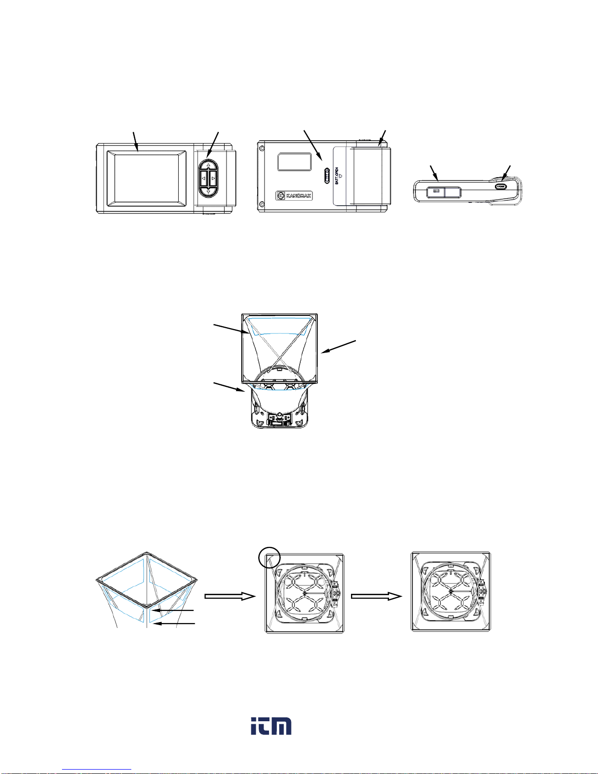
2. Capture Hood Structure.......................................................................................................2
2.1 Capture Hood Base....................................................................................................2
2.2 Main structure.............................................................................................................3
2.3 Fabric Hood................................................................................................................3
3. Installation and Assembling .................................................................................................3
3.1 Capture Hood Installation...........................................................................................3
3.2 Assembling the Frame (detail)....................................................................................4
3.3 Installing the Portable Handle.....................................................................................4
3.4 Installing the Main structure........................................................................................5
4. Operation directions ............................................................................................................5
4.1 Communication and Supplying Power with the AC Adapter .......................................5
4.2 Supplying Power with Batteries ..................................................................................6
4.3 ON/OFF......................................................................................................................7
4.4 Keypad Operation ......................................................................................................7
4.5 Incline Adjustment Settings of the Instrument.............................................................8
4.6 Back Pressure Compensation On / Off Settings.........................................................9
4.7 Measuring ................................................................................................................10
4.7.1 Start and enter into the main interface............................................................10
4.7.2 Single Measurement Mode ............................................................................10
4.7.3 Running Average Measurement Mode ........................................................... 11
4.7.4 Back Pressure Compensation Measurement Mode .......................................12
5. Display Menu settings .......................................................................................................12
5.1 Test Settings.............................................................................................................13
5.1.1 Test ID settings...............................................................................................14
5.1.2 Test Mode settings .........................................................................................15
5.1.3 Set Units of Measure for Airflow, Temperature, and Atmos ............................16
www. .com information@itm.com1.800.561.8187

2
5.1.4 Actual flow, Standard flow settings .................................................................17
5.2 General settings .......................................................................................................18
5.3 Data processing settings ..........................................................................................19
5.4 Communication settings ...........................................................................................20
5.5 Print Settings............................................................................................................21
6. Main Specifications............................................................................................................23
7. Common Trouble Shooting................................................................................................24
8. Warranty and After-service ................................................................................................25
8.1 Warranty...................................................................................................................25
8.2 After-service .............................................................................................................25
www. .com information@itm.com1.800.561.8187

1
1.Introduction
The model 6710 is used to measure the air flow at the supply and the exhaust points of an
HVAC system. There are several interchangeable hoods of various sizes so it’s easy to find one
that will match the size of the supply and exhaust points of any HVAC system.
The standard size hood is 2ft×2ft (610mm×610mm). Four additional sizes are also available
as options:
2ft×4ft (610mm×1220mm).
1ft×4ft (305mm×1220mm).
2ft×3ft (610mm×915mm).
3ft×3ft (915mm×915mm).
The capture hood is designed to fit tightly over the air port to eliminate any leakage which
could affect the accuracy of a measurement. Users can see the air port through the clear windows
at the top of the capture hood ensuring it is lined up correctly. Fiberglass poles support the fabric
hood.
A velocity matrix is fixed on the base and airflow is tested through sixteen measuring points on
the cross sections of the matrix. The sensor will measure airflow and correct for air pressure and
temperature ensuring an accurate reading every time.
1.1 Product features
zMeasure air flow, temperature and humidity at the same time
zTwo kinds of tests are available for supply flow and exhaust flow
zWide test range: 40~4300 m3/h
zLarge Storage capacity: 3000 records
z3.5 inch color LCD
zLCD tilts up to 30°for easy viewing
zBack pressure compensation
zAutomatic air pressure and temperature correction
zLight weight, compact configuration for easy transportation
www. .com information@itm.com1.800.561.8187

2
2. Capture Hood Structure
The capture hood consists of a fabric hood, main structure and an instrument base. The structural
drawing is below:
2.1 Instrument Base
1)The exterior structure of the base as below: 2)The internal structure of the base as below:
3)Matrix
There are sixteen measuring points for testing air flow.
Fabric hood
Instrument base
Main structure
Measurement
matrix
Back pressure plate
Frame poles
Portable handle Back pressure on/off
Test handle
Base button
Main structure
Measuring point for air flow
www. .com information@itm.com1.800.561.8187

3
2.2 Main structure
2.3 Fabric Hood
The fabric hood kit consists of a frame, and a fabric hood with four windows as shown below:
3. Installation and Assembling
3.1 Capture Hood Installation
1)Assemble the fabric hood and the frame as shown below:
Battery Compartment
Cover
Back
Cover lock
Use the angled corners ①and
the stitching ②as a guide to
ensure the hood is straight. If
the fabric hood is twisted it will
not assemble correctly.
③
Insert a frame pole into the
frame and hook it under the
corner of the hood ③.
Side view
POWER
Socket for
communicatio
Continue until all 4
corners are supported
by poles ④.
Fabric hood
Frame
Window
③
①
②
④
Keypad
Front view
Display LCD
www. .com information@itm.com1.800.561.8187

4
2)The figures below are provided as a reference.
a. Use the mark ①and the stitching as a guide to ensure the hood position.
b. Make sure the hood fully wraps around the base.
3.2 Assembling the Frame (detail)
Insert one end of a support pole into its pole mount in the base as in figure ①and the other
end into the frame corner as in figure ②. For the positions of the remaining 3 poles refer to figure
③, and repeat the steps as above.
Note:The support poles always cross in an “X” shape when the hood is assembled. To
remove the poles, simply reverse the steps.
3.3 Installing the Portable Handle
To install the handle line it up with the mounting hole as shown in step ①and ②below. Step
③shows the handle installed.
Note:The support poles and the portable handle should be disassembled before
packing the capture hood in the carrying case to avoid damaging the case.
①②③
①② ③
①
www. .com information@itm.com1.800.561.8187

5
3.4 Installing the Main structure
To install the Main structure ①, set the bottom of the panel in the holder on the unit base ②
and gently push the top of the panel backwards ③until it locks into place. To remove it, simply
reverse the procedure.
4. Operation directions
4.1 Communication and Supplying Power with the AC Adapter
Connect the main structure to a PC (refer to figure ①).
To power the instrument with the optional AC adapter, refer to figures ②and ③. When the AC
adapter is connected and batteries are installed, power will be supplied from the AC adapter.
The specification of the AC adapter is: I/P: AC 110-240V 50/60 HZ O/P: DC 5V/ 2A
①
②
③
①The main structure is connected to a PC.
③The AC adapter also supplies power for the
Capture hood.
②The AC adapter supplies power for the main
www. .com information@itm.com1.800.561.8187

6
4.2 Supplying Power with Batteries
¾4 AA-size batteries can be used for a power supply.
¾Press the compartment cover lock (refer to figure ①), and then slide the cover off to open
the battery compartment.
¾Put 4 AA-size batteries in and make certain the batteries are correctly oriented.
¾New alkaline battery or rechargeable Ni-MH battery can be used. Never mix battery types,
or battery leakage or damage to the instrument may occur.
¾Replace the compartment cover (refer to figure ②). The compartment cover will be
automatically locked.
¾When power is supplied with batteries, the current charge value will be displayed on the
upper of the LCD. When the batteries run out of power, the instrument will turn off.
Note:
1. Don't use a full_power battery with low power batteries.
2. It is recommended you change batteries when the power shows low.
Turn off
1. You can’t begin a new test.
2. You can’t use the incline adjustment settings of the instrument.
3. The test may stop if the battery is low during testing.
4. The adjustment settings of the instrument may stop when the battery is
low durin
g
ad
j
ustment.
①②
www. .com information@itm.com1.800.561.8187

7
4.3 ON/OFF
1. Getting started
The LCD is displayed below for reference:
2. Shut down
Press and hold 【POWER】for more than 2 seconds in any mode, and the instrument will turn
off automatically.
4.4 Keypad Operation
Keypad operations include the keypad on the control panel as well as the switches on the
base.
The keypad on the control panel is shown below. When a keypad turns gray in the illustration
on the screen, that particular function is invalid.
zMOVE: Change an option on the current mode.
zADJ: Change the current value.
(1)Press【POWER】for a while.
(2)Then you enter into the main interface as shown in the left
figure.
MOVE/ADJ/SAVE
MOVE/ADJ
SET/MENU/OK
ESC/START/STOP/BACK/EXIT
www. .com information@itm.com1.800.561.8187

8
zSAVE: Save the current test results.
zSET: Store changes or enter into the selected option’s next level interface.
zMENU: On the main screen holding this down for 2 seconds will enter into the main
“MENU”.
zOK: Pressing for 2 seconds will save the date or time in the “General Settings”,
Pressing for 2 seconds will delete saved data in the “Record Processing”.
zSTART: Begin a measurement in main menu.
zSTOP: Stop a measurement in main menu.
zBACK: Cancel or end an operation or return to the previous screen.
zEXIT: Return to the main menu.
zESC: Stop printing when printing.
Left / right switches on the base
Left switch on base
Press it once quickly to start or stop a measurement. Press and hold it in for at least 3
seconds to tilt the control panel and LCD screen downward.
Right switch on base
Press it once quickly to save the current data. Press and hold it in for at least 3 seconds to tilt
the control panel and LCD screen upward.
4.5 Incline Adjustment Settings of the Instrument
Start up the instrument and lift the capture hood to the approximate height you will be working
at. Press and hold the left button on the base to tilt the panel downward, or press and hold the right
switch to tilt it up. The buttons must be held down for a minimum of 3 seconds before the panel will
begin to tilt. While the panel is moving, you will hear an audible buzzing.
Left switch Right switch
www. .com information@itm.com1.800.561.8187

9
Note:
1. The instrument may turn off, when you attempt to adjust the incline
settings of the instrument if the battery display is at .
2. You can’t adjust the incline settings of the instrument when testing or if
you’re not in the main interface.
3. To conserve power,avoid tilting the screen unless necessary.
4.6 Back Pressure Compensation On / Off Settings
Turn the Back Pressure Compensation ON: Flip the switch ①to the down position until it is
locked. Make the back pressure plate parallel with the matrix plane.
Turn the Back Pressure Compensation OFF: Flip the switch ①to the up position until it is
locked. Make the back pressure plate vertical against the matrix plane.
①
Back Pressure Compensation ON
①
Right switch makes the panel tilt up. Left switch makes the panel tilt down.
Back Pressure Compensation OFF
①
www. .com information@itm.com1.800.561.8187

10
4.7 Measuring
4.7.1 Start and enter into the main interface
To start measuring, go to the main interface menu as shown below:
a.Test ID, Cycle——save the testing No. in Cycle and the corresponding Test ID.
b.Air flow display ——display the testing data of air flow.
c.Temperature, Humidity ——display the current temperature and humidity in real time.
d.Keypad function ——display the function of the keys in the current interface.
e.Test mode ——display the current testing mode: Single measurement, Run Avg
measurement and B.Press measurement.
f.Power supply mode ——display the current power supply from the AC adapter or the
batteries.
g.Brightness indicator ——display the current brightness of the LCD.
h.Date, Time ——display the current date and time.
Note: When “Act” is selected in the following three measurement modes,
please change the atmosphere Pressure setting in 5.1.4.
4.7.2 Single Measurement Mode
b
a
c
d
e
g
h
Test Mode:
Single
SAVE
START
MENU
2012 / 06 / 01 13 : 10 : 10
Test ID : 13 Cycle : 050
- - - - m³/h
25.4 ℃53.4 %RH
f
“SAVE”
“START”/”STOP”
www. .com information@itm.com1.800.561.8187

11
1)“Single” measurements are individual flow measurements. When you press “START”, the
instrument will begin measuring and the air flow value will be displayed as “- - - -”.
2)The test will stop automatically when the air flow is stable and a flow value with the
corresponding wind direction will be displayed. Air flow will be stable within 8 seconds.
The greater the air flow the shorter the time needed to stabilize.
3)After the measurement stops, press “SAVE” to record the testing value, if you do the
“Cycle” No. will increase by 1.
Note:The value will be recorded only when testing is completed in the “Single” mode. If
testing is interrupted before a stable airflow reading is displayed no data will be saved.
4.7.3 Running Average Measurement Mode
1)When “Run Avg” mode is selected, the instrument will constantly measure and display a
running average. Press “START” to begin the measurement.
2)During the test if the air flow is not stable, the flow reading will display “- - - -”, then once the
reading has stabilized a flow reading will be obtained and displayed every 1 second, and
the wind direction will be displayed in real time.
Note: The displayed air flow reading is a running average that is calculated based on the “Avg
Time” settings entered by the user. The greater the “Avg Time” the more stable the
tested air flow.
3)When auto-save is enabled, the testing flow values will be recorded at user-defined
intervals under the setting “Save Time”, and the “Cycle” No. will increase by 1. If auto-save
is not enabled the readings will not be saved during the test.
4)The instrument will run continuously in “Run Avg” mode until you press “STOP”. After you
press stop, the last reading and the related wind direction will be displayed. Press “SAVE”
to record the testing value, if you do the “Cycle” No. will increase by 1.
Test Mode :
Single
SAVE
START
MENU
2012 / 06 / 01 13 : 10 : 10
Test ID : 13 Cycle : 050
2890 m³/h
25.4 ℃53.4 %RH
Test Mode :
Single
SAVE
START
MENU
2012 / 06 / 01 13 : 10 : 10
Test ID : 13 Cycle : 050
- - - - m³/h
25.4 ℃53.4 %RH
www. .com information@itm.com1.800.561.8187

12
4.7.4 Back Pressure Compensation Measurement Mode
When measuring air flow in an environment with a strong wind or turbulent flow, it will produce
resistance for test air flow and system pressure. It is suggested you turn the Back Pressure
Compensation ON when the air flow is more than 1500 m3/h, otherwise you can test without the
Back Pressure Compensation ON.
1)When “B. Press” mode is turned on, press “START” and the measurement will begin.
2)When "Flap Open!" is displayed, close the Back pressure plate and press "START" to
start the measurement.
3) When the measurement stops, the air flow, as measured with Back Pressure
Compensation will be displayed.
4) After the measurement stops, press “SAVE” to save the data and the “Cycle” No. will
increase by 1.
5. Display Menu settings
(1)In the main interface, press for 2 sec to enter into
“MENU”.
(2)There are 5 option items in “MENU”:
1.Test Settings
2.General Settings
3.Record Processing
4.Communication
5.Print
MOVE
OK
EXIT
MENU
2. General Settings
3. Record Processing
4. Communication
5. Print
SET
1.Test Settings
1
www. .com information@itm.com1.800.561.8187

13
5.1 Test Settings
(1)Press or to select “Test Settings”, and press to
enter into “Test Settings”. Press return to the main
interface.
(2) The option items in “Test Settings” are as follows:
1. Test ID
2. Test Mode
3. Unit
4. Act. Std (Actual / Standard air flow setting)
MOVE
OK
EXIT
MENU
2. General Settings
3. Record Processing
4. Communication
5. Print
SET
1.Test Settings
1
MOVE
OK
BACK
Test Settings
1. Test ID
2. Test Mode
3. Unit
4. Act.Std SET
Single
Std
1
www. .com information@itm.com1.800.561.8187
Other manuals for 6710
2
Table of contents
Other Kanomax Ventilation Hood manuals
Popular Ventilation Hood manuals by other brands

Sirius Satellite Radio
Sirius Satellite Radio ALFRESCO SLEM80 installation instructions

Baumatic
Baumatic BT26 instruction manual

Samsung
Samsung NK36M3050PS Installation instruction guide

FAL
FAL AR-60-303 Installation and user manual

Siemens
Siemens LI67SA530A Instructions for installation and use

Caple
Caple DD820BK instruction manual