Kanomax TABmaster 6715 User manual

TABmaster Model 6715
Instruction Manual
Be sure to read this manual thoroughly before using the instrument ,
fully understand and pay attention to each cautions mentioned.
Please well-keeping this manual for long time service reference .
01003
14.10

1
CONTENTS
Product Configuration..................................................................................................................... 3
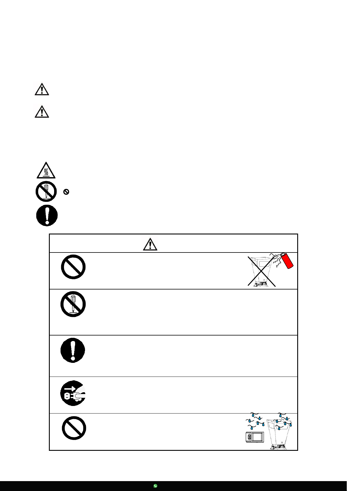
Caution........................................................................................................................................... 5
1. Introduction ................................................................................................................................ 7
1.1. Features............................................................................................................................. 7
1.2. Specifications..................................................................................................................... 7
2. Outlook & Structure.................................................................................................................... 8
2.1. Base structure.................................................................................................................... 8
2.2. Micromanometer ............................................................................................................... 9
3. Se ttubg up................................................................................................................................... 9
3.1. Capture Hood.................................................................................................................... 9
3.2. Velocity Grid.....................................................................................................................10
3.3. Pitot tube..........................................................................................................................11
3.4. Micromanometer ..............................................................................................................11
3.5. Shoulder Strap..................................................................................................................11
4. Operating Instruction .................................................................................................................12
4.1. Power supply ....................................................................................................................12
4.2. Start On / Power Off .........................................................................................................12
4.3. Keypad operation..............................................................................................................13
5. Function test...............................................................................................................................14
5.1. User Interface ...................................................................................................................14
5.2. Single Mode ......................................................................................................................15
5.3. Average Mode ...................................................................................................................15
5.4. Back Pressure Mode ..........................................................................................................15
6. Menu setting...............................................................................................................................16
6.1. General setting..................................................................................................................17
6.1.1. Date........................................................................................................................17
6.1.2. Time .......................................................................................................................17
6.1.3. Auto Off..................................................................................................................17
6.1.4. Backlighting............................................................................................................18
6.1.5. Communication.......................................................................................................18
6.2. Test setting........................................................................................................................19

2
6.2.1. Tools .......................................................................................................................19
6.2.2. ID application .........................................................................................................20
6.2.3. Test Mode ...............................................................................................................20
6.2.5. Data record.............................................................................................................21
6.2.6. Standard/Actual test................................................................................................21
6.2.7. Compensation factor ...............................................................................................22
7 Error and Troubleshooting...........................................................................................................23
8 Warranty and Service..................................................................................................................24
8.1. Product Warranty.............................................................................................................24
8.2. After service......................................................................................................................24

3
Product Configuration.
6715 Standard:
Item. YƚLJ
Mic romanometer Model 6700
1
Instrument Base
1
Fabric Hood: 2ft×2ft
1
Carrying case
1
Portable handle 1
Frames
1
Poles
4
Communication cable 1
Calibrat ion c er tific ate 1
CD-Rom˄Manual and software inside˅
1
Quick-Guide
1
6715 Optional Parts:
Item. Specifications
Spare hood 2x2ft
Spare hood 2x4ft
Spare hood 1x4ft
Spare hood 3x2ft
Spare hood 3x3ft
Spare hood 500x500mm
Poles
Capture Hood Stand Up to 3.4m with capture hood
Communication cable
Printer
AC adapt er DC5V
International plug adapter
Carrying case
Velocity Grid
Pitot tube (2.3 x 200mm)
Pitot tube (4 x 300mm)
Pitot tube (8 x 500mm)
Pressure tubing
2*250cm

4
6700 Standard:
Item.
YƚLJ
Mic romanometer Model 6700 1
Carrying case
1
Pressure tubing 2
Communication cable 1
Calibrat ion c er tific ate 1
CD-Rom˄Manual and software inside˅
1
Quick-Guide 1
6700 Optional Parts:
Item. Specifications
Velocity Grid
Pitot tube (2.3 x 200mm)
Pitot tube (4 x 300mm)
Pitot tube (8 x 500mm)
Pressure tubing 2*250cm
Shoulder Strap
Printer
AC adapt er DC5V
International plug adapter
Communication cable

5
Caution.
The symbols for warning mentioned in this manual are defined below:
ǒsymbols classificationsǓ
Danger: To Prevent Serious Injury or Death
Warnings in this classification indicate a danger that may resultin serious injury or death if not observed .
Caution: To Prevent Damage to the Product
Warnings in this classification indicate a risk of damage to the product that may void the product warrantyif not
o b s e r ve d .
ǒDescription of SymbolsǓ
䂦This s ymbol indi ca tes a condi tion tha t re qui res caution (including danger). The sub je ct of ea ch cauti on is
illustrated inside the triangle .
This symbol indicates a prohibi tion. Do no t take the p rohibi ted a ction sho wn inside or nea r this s ymbol .
ƽThis symbol indicates a mandatory action. A specific action is given near the symbol.
WARNING
Heated forbidde n
ƻ
Never bring the fabric hood to a flammable gas
a tmosphe re .
Ăotherwise, the heat may cause a fire or explosion.
Disassemble
prohi bition
ƻDo not disassembly or refit the instrument.
Ăotherwise, ma y cause the electric shock or a fire.
Usi ng prope rl y
ƻUsing p rope rl y unde r the instru ction manual.
Ăotherwise, ma y cause sensor damaged or an electric shock evena fire.
Usi ng prope rl y
ƻIf abnormal smells, noises or smoke occur, or if liquid enters the instrument, pull out
the AC adapter and remove the batteries immediately. Then send it to the
maintenance Dept. of KANOMAX for after servi ce.
Ăor, there is possible of an electri c shock or a fire or instrument malfunction.
Forbidde n
ƻDo not e xpose the fabri c hood, base and the ins trument
noumenon in the rain.
Ăotherwise, may cause an electric shock, an fire and an
pe rs o n i n ju re .

6
CAUTION
Using properly
ƻAlwa ys unplu g when the instrumen t no t in use.
ĂFailure to do so may cause an electric shock, an fire or circuit damage.
Using properly
ƻRemove the ba tteries when s toring the instrument for a l ong period. Do not leave
the e xhaused batte ries in the ba ttery compa re ment and e xchange the ba tte reis on
time .
ĂFailure to do so ma y cause the batteries leakage and the instrument damage.
Using properly
ƻMatching the corre ct AC adapter outward as reqested.
Ăor ma y ca use the ins tru men t dama ge .
Forbidde n
ƻDo not wipe the instrument with a vola tile solvent.
Ăthe body may deform or deteriorate. Use a soft dry cl oth to remove stains. If stains
pe rsist, soak the cloth in a neu tral de te rgent a nd wipe the i nstrument with the so ft
cloth. Never use volatile solvents such as thinner or benzene .
Forbidde n
ƻDo not use or lea ve the ins trument in a high
temperature, high humidity or dusty environment. Do
notlea ve the instrume nt unde r di re ct sunlight.
Ăothe rwise , the instrument may not function p rope rl y
out of the spe ci fied ope ra ting condi tions or the inside
co mponents damage d .
Forbidde n
ƻNe ve r d ropping the uni t o r pla cing hea vy ob je cts on i t
ĂIt may cause damage or malfunction to the instrument

7
1. Introduction
TABmaster Model 6715 is a kind of intelligent test instrument with multi functional of airflow test, velocity
test and micro-Differential pressure test. Its widely used in air flow and velocity testing of air - c onditioning,
HAVC system and other places, especially for the high precision micro differential pressure test.
1.1. Features
3.5 inch true color LCD.
Available measuring the air flow, velocity, temperature and humidity at the same time.
Two kinds of tests are available of in flowing and exhaust flowing.
Back pressure compensation.
Ultra-large Storage capacity: 8000 records
Blue tooth communication makes remote monitoring and data transferring available.
Light weight, compact configuration for easy carrying.
Data printing or transferring to the computer.
1.2. Specifications
Items Specifications
Air flow
Test range 404300 m
3
/h
Accuracy ±3% of readings ± 8m
3
/h˄˚85m
3
/h˅
Resolution 1 m
3
/h
Air velocity
Test range 0.1540 m/s˄Pitot Tube˅ǃ 0.1515 m/s˄Vel ocity Grid)
Accuracy ±3% of readings ±0.05m/s˄˚0.25m/s˅
Resolution 0.01m/s
Differential
pressure
Test range -2500~2500 Pa
Accuracy ±0.25% of readings ±1Pa
Resolution 0.001 Pa
Temperature
Test range 060ć
Accuracy ±0.5ć
Resolution 0.1ć
Humidity
Test range 0~100%RH
Accuracy ±3%RH˄10~90%RH˅
Resolution 0.1%RH
Absolute
pressure
Test range 70~130 kPa
Accuracy ±2% of readings
Resolution 0.1 kPa
Operation Temp. 0~60ć˄non condensing ˅
Storage Temp. -20~70ć˄non condensing˅
Power Source 4 pcs of AA-size buttery ( approx. 9hrs available˅or DC5V Adapter
Weig ht 3.6kg approx.

8
2. Outlook & Structure
2.1. Base structure
1ˊOutlook
2ˊInternal view 3ˊGrid
Te s ti n g
point
Fa b ri c
Hood
Mi cromano me te r
Pi vot
Wi ndow
Frame
Poles
Instrument
Base
Poles
Grid
Ba c k p re s s u re pl a te
Test handle
Ba s e b u t to m
Mi cromano me te r
Ba ck p re s su re
ON/OFF
Potable handle
Adjus t handle

9
2.2. Micromanometer
3. Settubg up
3.1. Capture Hood
1ˊFabric Hood & ba sement
ǃ
Note˖
1˅Make sure the elastic band of the fabric hood is placed exactly as shown (Figure(3)) to ensure a good fit.
The elastic band must lineup with the top lip of the base a s shown. If you don¶t line it up correctly, the
hood might slide off the base whe n you insert the poles.
2˅Use the 4 positioning holes on the base stitching as a guide to ensure the hood fully wraps around the
base..
2ˊFrame Poles
Front view
To p vi e w Bottom view
Ba ck
Coverlock
Mini US B Port
Poweron/off
Ai r port
(+)
Ai r port
(-)
Ke ypad
Display LCD
Ba tte ry Co mpa rtme n t Co ve r
˄
1
˅
˄2˅˄3˅˄4˅

10
Note: dŚĞƉŽůĞƐĂůǁĂLJƐĐƌŽƐƐ ŝŶĂŶy ƐŚĂƉĞǁ ŚĞŶĂ ƐƐĞŵ ďůing. To remove the poles, simply reverse the steps.
3ˊPotable handle
Note: Release the poles and portable handle when packing in the carring case to avoid case damaged.
4ˊMicromanometer & basement
Note: 1˅Correct install the micromanometer to the base with the same S/N No.
2˅Do not cross- insert the Air pines just refer to the figure as above.
3.2. Velocity Grid
Air velocity testing can be achieved when micromanometer work together with the velocity Grid.
ķ
ĸ
(+) (-)

11
Note: Mounting angle between the Grid and handle can be adjusted as request.
3.3. Pitot tube
Air flow and velocity testing can be achieved when micromanometer work together with Pitot tube.
3.4. Micromanometer
Differential pressure testing can be achieved by using the micromanometer.
Device
under test
3.5.Shoulder Strap
When testing by Vel ocity GridǃPitot tubeǃMicromanometer as the tool, for convenient view and easy
operation, the shoulder strap can be fit for using.
˄
+
˅˄
-
˅
S ta ti c p res s u re
port
Testing point
˄+˅˄-˅
˄+˅˄-˅
Ha ndle
Grid

12
4. Operating Instruction
4.1. Power supply
1ˊPower by AC adapter. AC adapter w ill be as the priority power supply when the AC adapter and batteries are
all available using. The specification of the AC adapter is: I/P:AC 110-240V 50/60HZ O/P:DC 5V/2ADŽ
1˅AC adapter for the master 2˅AC adapter for Capture Hood
2ˊPower by battery
4 AA-size batteries can be used for a power supply.
Press the compartment cover lock (refer to figure indicating ķ/ĸ), and then slide the cover off to open
the battery compartmentDŽ
Put 4 AA-size batteries in and make certain the batteries are correctly oriented.
New alkaline battery or rechargeable Ni-MH battery can be used. Never mix battery types, or battery
leakage or damage to the instrument may occur.
Replace the compartment cover (refer to figure Ĺ). The compartment cover will be automatically locked.
When power is supplied with batteries, the current charge value will be displayed on the upper of the LCD.
When the batteries run out of power, the instrument will tur n off.
Note˖
1˅Do not test with low battery power.
2˅Do not mixing use full power battery with low power ones for ensure testing well.
3˅Change the batteries in time when power shows low for ensure testing well.
4.2. Start On / Power Off
ķ
ĸ
Ĺ
P
owe r off

13
2014 / 03 / 20 13 : 10
20.5 ć30.7 %RH
m
3
/h
Atmos: kPa
Ready
ID:
Cycle:
Mode:
01
001
Single
START SAVE MENU
99.0
1. Start On
Press buttonǏPOWERǐfor 2 seconds for start On, displaying KANOMAXthen enter into the testing
interface.
2. Power Off
PressǏPOWERǐfor 2 seconds, shut down and power off.
4.3. Keypad operation
Keypad panel includes control buttons, back-pressure switch and LCD adjusting keys.
1ˊControl buttons:
UP˖Value increasing or Cursors upward moving.
SAVE˖Save the current test results
SET˖^ƚŽƌĞĐŚĂŶŐĞƐŽƌĞŶƚĞƌŝŶƚŽƚŚĞƐĞůĞĐƚĞĚŽƉƚŝŽŶƐŶĞdžƚůĞǀĞůŝŶƚĞƌĨĂĐĞ
MENU˖On the main screen holding this down for 2 seconds ǁŝůůĞŶƚĞƌŝŶƚŽƚŚĞŵĂŝŶDEh
OK˖In tŚĞ'ĞŶĞƌĂů^ĞƚƚŝŶŐ , pressing for 2 seconds will save the date or time ;
While ŝŶƚŚĞZĞĐŽƌĚWƌŽĐĞ ƐƐŝŶŐ , pressing for 2 seconds will delete saved data.
START˖Begin a measurement in main menu
STOP˖Stop a measurement in main menu
BACK˖Cancel or e nd an operation or return to the previous screen
EXIT˖Return to the main menu
ESC˖Stop printing when pr inting
DOWN:˖Value decreasing or Cursors downward moving
2ˊBack pressure switch for on/off
Note ˖
1) If you are not in the back pressure mode, shut down the back pressure plate and lock the
switch to avoid testing errors.
2) If the airflow is greater than 1500m3/h (883CFM), testing in back-pressure Mode is
recommended according to testing procedures.
POWER
START/STOP SAVE
UP/S AVE
DOWN
SET/MENU/OK
START/STOP/
BACK/EXIT/ESC

14
3ˊLCD adjusting
Note ˖
1˅Please switching the handle slow gently during LCD adjusting.
2˅Stop turning when reach to the bound, for avoiding over turning and handle falling down.
5. Function test
Besides the airflow test, if along with other optional products, test air velocity and micro -differential
pressure is available.
5.1. User Interface
Testing information, parameter settings and the testing conditions will be displayed on the main interface.
A. Date and time ²² real-time display the current date and time
B. Testing data display ²² airflow ǃair velocity ǃdifferential pre ssure and etc.
C. Tools icon ²² working tools display
D. Testing condition ²² temperature ǃhumidity or absolute pressure displaying according to the
Ba ck p res s u re
On
Ba ck p re s su re
Off
2014 / 03 / 20 13 : 10
20.5
ć
30.7
%RH
m3/h
Atmos: kPa
Ready
ID:
Cycle:
Mode:
01
001
Single
START SAVE MENU
99.0
B
C
D
E
A
I
H
G
F
J

15
working tools.
E. Keypad ²² current status indicating and the grey state is not available.
F. Testing mode ²² display the current testing mode
G. Cycle²² recorded Cycle quantity
H. ID²² current ID quantity
I. Power supply ²² AC adapter or batteries
J. Blue tooth status ²² when blue tooth working, the icon display or no icon display with closed.
5.2. Single Mode
Note˖
1˅START: Left-button for the Micromanometer or instrument base
2˅After testing start for about 8s with stably measuring,output displaying the test data and testing wind
direction.
3˅Testing stop when finish outputting.
4˅Press S AVE for data record with adding 1 to the Cycle value.
5˅Same testing method with the capture hood when using the Velocity GridǃPitotǃMicromanometer.
5.3. Average Mode
Note˖
1˅START: Left-button for the Micromanometer or instrument base.
2˅After testing start for about 8s with stably measuring , output displaying the test data for the first time.
3˅Go on the testing with freque ncy of 1s for data updating.
4˅The continuously outputting is as the average data and be related with the ĀAvgTimeāset by user. More
larger of the value ofĀAvgTimeāwill get more stable of the testing data.
5˅If auto-save function On, testing data will be recorded automatically according to the setting ³AutoSave´
and value of ³Cycle´will be added automatically.
6˅Press ³STOP´, testing stop. And ³STOP´will be as the Left-button for the Micromanometer or instrument
base.
7˅Same testing method with the capture hood when using the Velocity GridǃPitotǃMicroma nometer.
5.4. Back Pressure Mode
2014 / 03 / 20 13 : 10
20.5 ć30.7 %RH
m
3
/h
Atmos: kPa
Waiting...
ID:
Cycle:
Mode:
01
001
Avg
99.0
STOP SAVE MENU
2014 / 03 / 20 13 : 10
20.5 ć30.7 %RH
m
3
/h
Atmos: kPa
32
ID:
Cycle:
Mode:
01
001
Avg
99.0
STOP SAVE MENU
1
.Read y fo r tes ting
2. Testing 3. test output
2014 / 03 / 20 13 : 10
20.5 ć30.7 %RH
m
3
/h
Atmos: kPa
31
ID:
Cycle:
Mode:
01
001
Avg
99.0
STOP SAVE MENU
4. testing stop
STOP
2014 / 03 / 20 13 : 10
20.5
ć
30.7
%RH
m3/h
Atmos: kPa
Ready
ID:
Cycle:
Mode:
01
001
Avg
START SAVE MENU
99.0
S TART
2014 / 03 / 20 13 : 10
20.5
ć
30.7
%RH
m
3
/h
Atmos: kPa
Ready
ID:
Cycle:
Mode:
01
001
Single
START SAVE MENU
99.0
2014 / 03 / 20 13 : 10
20.5
ć
30.7
%RH
m
3
/h
Atmos: kPa
Waiting...
ID:
Cycle:
Mode:
01
001
Single
99.0
STOP SAVE MENU
2014 / 03 / 20 13 : 10
20.5
ć
30.7
%RH
m
3
/h
Atmos: kPa
32 ID:
Cycle:
Mode:
01
001
Single
99.0
START SAVE MENU
S TART
1. Read y fo r tes tin g
ᕙ⌟⢊ᗕ
2
. Testing 3. tes t output

16
In order to reduce the measure error of the pressure loss,which causing from the hood to the system and
get the more real air flow, we suggest testing under the Back Pressure Mode when air flow more than 1500
m3/h.
Note˖
1˅START: Left-button for the Micromanometer or instrument base.
2˅After testing start for about 8s , indicating KƉĞŶ&ůĂƉ. It¶s time for switching on the Back-Pressure Plate
as needed.
3˅When Back-Pressure Plate opened On, tip of KƉĞŶ&ůĂƉ disappear.
4˅Press START for about 8s, testing stop, real airflow outputting with back pressure compensation.
5˅Press S AVE for testing data record and the meanwhile, value Cycle added 1.
6˅When select Velocity GridǃPitot tubeǃMicromanometer for testing, Back-Pressure compensation will be
not available.
6. Menu setting
when stop for ready, press for 2s for enter into the menu.
MENU
General Setting
Test Setting
UP
DOWN
OK
EXIT
SET
2014 / 03 / 20 13 : 10
20.5
ć
30.7
%RH
m3/h
Atmos: kPa
Ready
ID:
Cycle:
Mode:
01
001
Avg
START SAVE MENU
99.0
˄1˅2 optional settings ˖
1˅Basi c setting
2˅Test setting
3˅Working tool displayi ng belo w
2s
4. switch on Back-Pre s s u re Pl a te
5. testing ready6. testing
2. Testing
1.Rea d y fo r tes ting
7. test output 8. shut off the pla te 9. testing ready
2014 / 03 / 20 13 : 10
20.5 ć30.7 %RH
m
3
/h
Atmos: kPa
Ready
ID:
Cycle˖
Mode:
01
001
B.P
START SAVE MENU
99.0
2014 / 03 / 20 13 : 10
20.5 ć30.7 %RH
m3/h
Atmos: kPa
2000
ID:
Cycle:
Mode:
01
001
B.P
99.0
START SAVE MENU
3
. Ba ck-pressure On promoting
2014 / 03 / 20 13 : 10
20.5
ć
30.7
%RH
m
3
/h
Atmos: kPa
Ready
ID:
Cycle:
Mode:
01
001
B.P
START SAVE MENU
99.0
2014 / 03 / 20 13 : 10
20.5 ć30.7 %RH
m3/h
Atmos: kPa
Open Flap !
ID:
Cycle˖
Mode:
01
001
B.P
START SAVE MENU
99.0
2014 / 03 / 20 13 : 10
20.5
ć
30.7
%RH
m
3
/h
Atmos: kPa
Waiting...
ID:
Cycle:
Mode:
01
001
B.P
99.0
STOP SAVE MENU
S TART
2014 / 03 / 20 13 : 10
20.5 ć30.7 %RH
m
3
/h
Atmos: kPa
Ready
ID:
Cycle˖
Mode:
01
001
B.P
START SAVE MENU
99.0
2014 / 03 / 20 13 : 10
20.5 ć30.7 %RH
m3/h
Atmos: kPa
Waiting...
ID:
Cycle:
Mode:
01
001
B.P
99.0
STOP SAVE MENU
S TART

17
6.1. General setting
6.1.1. Date
6.1.2. Time
6.1.3. Auto Off
When instrument not in use, it will be turn off automatically according to Auto-Off time setting to avoid
power waste.
MENU
General Setting
Test Setting
UP
DOWN
OK
EXIT
SET
˄1˅Basic setting˖
1˅Date
2˅Time
3˅Auto Shut
4˅Backlight
5˅Communicate
2s
(1) press or for data modify.
(2)press , for sele cting Year/Month/day.
(3)Press for 2s for save settings.
(4)Press for qui t.
General Setting
1.
2.
3.
4.
5.
Date
Time
Auto Shut
Backlight
Communicate
UP
DOWN
OK
BACK
SET
2014 / 03 / 20
13 : 10
Off
High
General Setting
1.
2.
3.
4.
5.
Date
Time
Auto Shut
Backlight
Communicate
UP
DOWN
OK
BACK
SET
20 / 03 / 20
13 : 10
Off
High
14
General Setting
1.
2.
3.
4.
5.
Date
Time
Auto Shut
Backlight
Communicate
UP
DOWN
OK
BACK
SET
2014 / 04 / 01
13 : 10
Off
High
General Setting
1.
2.
3.
4.
5.
Date
Time
Auto Shut
Backlight
Communicate
UP
DOWN
OK
BACK
SET
2014 / 04 / 01
13 : 10
Off
High
01
General Setting
1.
2.
3.
4.
5.
Date
Time
Auto Shut
Backlight
Communicate
UP
DOWN
OK
BACK
SET
2014 / 03 / 20
13 : 10
Off
High
2s
2s
(1)Press or for data modify.
(2)Press for hour/minute selection.
(3)Press for 2s for save settings.
(4)Press for quit.
(1)ᣝ䬂䖯㸠᭄ؐᬍDŽ
(2)ᣝ䬂ˈᯊ/ߚ䗝乍ᕾ⦃⿏ࡼDŽ
(3)䭓ᣝ 䬂2sˈֱᄬ䆒㕂DŽ
(4)ᣝ䬂ˈ䗔ߎ䆒㕂DŽ
General Setting
1.
2.
3.
4.
5.
Data
Time
Auto Shut
Backlight
Communicate
UP
DOWN
OK
BACK
SET
2014 / 03 / 20
: 10
Off
High
13
General Setting
1.
2.
3.
4.
5.
Date
Time
Auto Shut
Backlight
Communicate
UP
DOWN
OK
BACK
SET
2014 / 03 / 20
13 : 10
Off
High
General Setting
1.
2.
3.
4.
5.
Date
Time
Auto Shut
Backlight
Communicate
UP
DOWN
OK
BACK
SET
2014 / 03 / 20
15 : 15
Off
High
General Setting
1.
2.
3.
4.
5.
Data
Time
Auto Shut
Backlight
Communicate
UP
DOWN
OK
BACK
SET
2014 / 03 / 20
15 : 15
Off
High
15

18
6.1.4. Backlighting
Adjust the LCD lighting according to the environmental brightness for the be st view ing. And meanwhile, the
lower the brightness, the less battery power will be needed.
6.1.5. Communication
Communicate with PC, printer and Bluetooth are available. Data transfer or remote monitoring is available
by selecting communicating way.
Note˖
1˅PC communication means to save the testing record to the computer. And the communication cable and
software reserved for data-fetching are necessary for using together. Refer to the << Manuel for Data
fetching Software>> .
2˅For printing out the testing record, the optional printer and cables for special are necessary. Printer baud
rate is set to 19200 bps and Do not change it. Refer to the << Manuel for RD series Mini printer >> .
3˅Bluetooth make the remote control and data monitoring available by Hand phone. And our APP software is
necessary for using together. Refer t o the << Manuel for TAB Mobile>>.
4˅Shut off the switch whe n not use the Bluetooth communication for improving battery life.
(1)Press or fo r options cha nge.
(2)Press for save settings .
(3)Press for quit.
(1)Press or fo r options cha nge.
(2)Press for save settings .
(3)Press for qui t.
(3)ᣝ䬂ˈ䗔ߎ䆒㕂DŽ
General Setting
1.
2.
3.
4.
5.
Data
Time
Auto Shut
Backlight
Communicate
UP
DOWN
OK
BACK
SET
2014 / 03 / 20
13 : 10
Off
20 min
10 min
30 min
60 min
General Setting
1.
2.
3.
4.
5.
Data
Time
Auto Shut
Backlight
Communicate
UP
DOWN
OK
BACK
SET
2014 / 03 / 20
13 : 10
Off
20 min
10 min
30 min
60 min
General Setting
1.
2.
3.
4.
5.
Date
Time
Auto Shut
Backlight
Communicate
UP
DOWN
OK
BACK
SET
2014 / 03 / 20
13 : 10
Off
High
General Setting
1.
2.
3.
4.
5.
Date
Time
Auto Shut
Backlight
Communicate
UP
DOWN
OK
BACK
SET
2014 / 03 / 20
13 : 10
10 min
High
General Setting
1.
2.
3.
4.
5.
Date
Time
Auto Shut
Backlight
Communicate
UP
DOWN
OK
BACK
SET
2014 / 03 / 20
13 : 10
Off
High
General Setting
1.
2.
3.
4.
5.
Date
Time
Auto Shut
Backlight
Communicate
UP
DOWN
OK
BACK
SET
2014 / 03 / 20
13 : 10
Off
Low
High
Normal
General Setting
1.
2.
3.
4.
5.
Date
Time
Auto Shut
Backlight
Communicate
UP
DOWN
OK
BACK
SET
2014 / 03 / 20
13 : 10
Off
High
Low
Normal
General Setting
1.
2.
3.
4.
5.
Date
Time
Auto Shut
Backlight
Communicate
UP
DOWN
OK
BACK
SET
2014 / 03 / 20
13 : 10
Off
Low

19
5˅If other settings need to be changed when Bluetooth successful communication, you nee d to shutdown
Bluetooth firstly t hen enter the menu to change ot her settings. Just as below shown:
6.2. Test setting
6.2.1. Tools
2014 / 03 / 20 13 : 10
20.5 ć30.7 %RH
m3/h
Atmos: kPa
32
ID:
Cycle:
Mode:
01
001
Avg
START SAVE OFF
99.0
2014 / 03 / 20 13 : 10
20.5
ć30.7 %RH
m3/h
Atmos: kPa
32
ID:
Cycle:
Mode:
01
001
Avg
START SAVE MENU
99.0
2s
Communicate
1.
2.
3.
Computer
Printer
Bluetooth
UP
DOWN
OK
BACK
SET
Off
Print
1.
2.
Print By IDs
Print By Cycles
UP
DOWN
OK
BACK
SET
Communicate
1.
2.
3.
Computer
Printer
Bluetooth
UP
DOWN
OK
BACK
SET
Off
Communicate
1.
2.
3.
Computer
Printer
Bluetooth
UP
DOWN
OK
BACK
SET
Off
Computer
Comfirm the Connection
UP
DOWN
OK
BACK
SET
Waiting...
Communicate
1.
2.
3.
Computer
Printer
Bluetooth
UP
DOWN
OK
BACK
SET
On
General Setting
1.
2.
3.
4.
5.
Date
Time
Auto Shut
Backlight
Communicate
UP
DOWN
OK
BACK
SET
2014 / 03 / 20
13 : 10
Off
High
Test settings˖
1˅Select Tool
2˅Test ID
3˅Test Mode
4˅Unit
5˅Data Record
6˅Standard/Actual testing
7˅Compensati on fact or
MENU
General Setting
Test Setting
UP
DOWN
OK
EXIT
SET
Test Setting
1.
2.
3.
4.
5.
Select Tool
Test ID
Test Mode
Unit
Data Record
UP
DOWN
OK
BACK
SET
RunAvg
6.
7.
Std/Act
K factor 1.000
Act
Other manuals for TABmaster 6715
1
Table of contents
Other Kanomax Ventilation Hood manuals
Popular Ventilation Hood manuals by other brands

ROBLIN
ROBLIN LINEAR 900 CENTRALE Dimensions

Faber
Faber Value PB 4 2L Cream A60 manual

Proline
Proline Island Pro installation guide

Jenn-Air
Jenn-Air JXU9130WP Installation Instructions and Use & Care Guide

AEG
AEG EFA 55 Installation and operating instructions

Blaupunkt
Blaupunkt 5DW66750AU Instruction on mounting and use