KAPtery SliderPro 200 User manual

Page 1of 3
User Guide for the KAPtery
SliderPro 200
See this guide at KAPtery.com/guides
Technical support: http://kaptery.com/contact/
The three components of the SliderPro 200, along with
a digital camera and certain Kodak slide projectors,
allow the unattended copying of every color slide in a
slide tray or stack loader.
1. The SliderLamp replaces the too bright (and also
hot, fragile, and expensive) halogen projector lamp.
2. Your digital camera rests horizontally on the
SliderPlate at the level of the slide projector’s lens.
3. Your camera and projector can be operated
automatically with the SliderSwitcher.
All changes made to the slide projector are temporary –
the projector can be returned to normal function in a
few minutes.
SliderLamp
With some Kodak projectors that allow the lamp
housing to be removed, the SliderLamp can slide in to
replace the housing and illuminate the slide. Set the
original lamp housing aside in a safe place –it can be
reinserted for normal use.
The SliderLamp includes a 2.5 watt LED lamp and three
diffusers to provide a bright, even, background light.
The SliderLamp comes with a 12 volt power supply so it
is independent of the projector’s power.
The LED lamp snaps into place at the rear of the
SliderLamp. After handling the SliderLamp, check to
make sure the lamp is well seated.
The SliderLamp housing should be slid (angled and
wiggled) into the projector lamp cavity and positioned
to produce even illumination for the slide. The front of the SliderLamp should be at least 3/4” from the slide (to keep
the front diffuser out of focus range). Some projectors will not allow the SliderLamp to get any closer than that. Some
trial and error may be required to find the best position for the SliderLamp, but any position will produce results that
look good to the unaided eye. Aim the SliderLamp a bit to the left (from the rear of the projector) and results should be

Page 2of 3
good. If you can measure the brightness across a photo taken of a blank slide, more precise adjustment can be made.
The free FIJI (https://imagej.net/software/fiji/) can make such measurements. When you are satisfied with the results,
lock in the position of the SliderLamp with some pieces of cardboard or tape (not included).
It is best to have the SliderLamp powered on only when the projector fan is running. The bulb does not get very hot, but
it is contact with PLA plastic which gets soft when warm (130°F).
The color of the SliderLamp is similar to the warm color of a tungsten bulb. It is best to use the custom white balance
feature of your camera to compensate for this so your slide copies retain their original color balance. A blank slide is
included for this. Fill the frame with the light from the SliderLamp (exclude the slide mount) when setting the white
balance. A test photo of a blank slide should then be steely gray.
The SliderLamp fits nicely in the Carousel 4400 and 4600 projectors and probably other 4000 series models (but has not
been tested on them). It should also fit in Ektagraphic III projectors and maybe other Ektagraphic projectors (but has not
been tested in them).
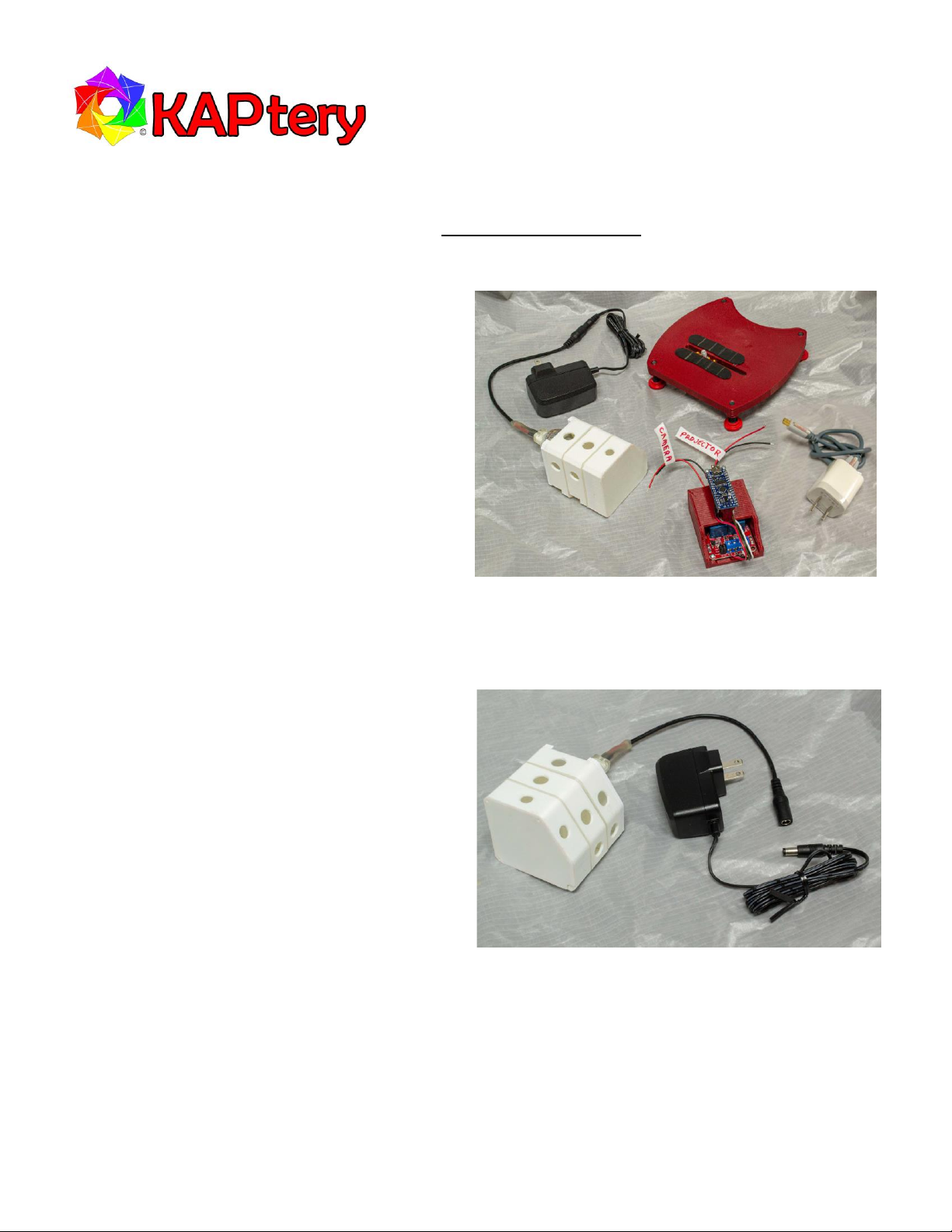
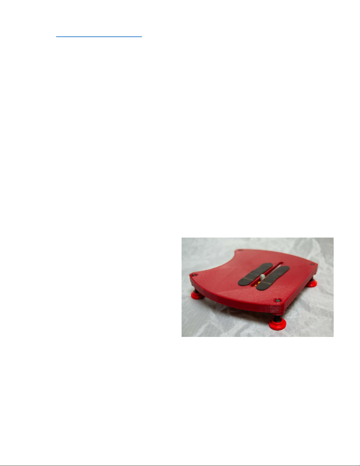
SliderPlate
Remove the projector lens and set it aside in a safe place. Use the projector’s front tilt control and rear leveling foot to
make the projector as horizontal and as possible. Attach your camera (with a long focal length macro lens, e.g., 80mm to
120mm for APS-C sensors) to the SliderPlate with the included tripod screw. If your lens does not touch the SliderPlate,
you can insert something to prop it up (without interfering with the focus ring) to make it more solid. Position the
camera and plate so the lens points into the projector’s empty lens opening and the camera’s optical axis is aligned with
the projector’s optical axis. The height of the camera can be adjusted with the red thumb screws on the four leveling
feet.
Turn on the projector and have a slide drop into position
for projection. Plug in the SliderLamp and look through
the viewfinder of your camera. Move the SliderPlate and
camera until the slide satisfactorily fills the frame and is
in focus. View the camera from above and from the side
and adjust the position and tilt of the camera until the
lens seems to be on the axis of the projector’s empty
lens tube. Then make final adjustments while looking
through the camera viewfinder and focusing on the
slide.
The non-slip feet on the projector and the SliderPlate
prevent them from most unintended movements. Mark
the position of the projector and SliderPlate with tape so
they can be returned close to the correct position in case
either has to be moved (e.g., to change the camera
battery).
To fill the frame with certain slide formats (e.g., 126 film or Super 127 film) the SliderPlate can be slid back. Slides should
be sorted by format when organized in Carousel trays so the SliderPlate can stay in the same position while copying
batches of slides.

Page 3of 3
SliderSwitcher
Digital copies of color slides can be made without the
SliderSwitcher by manually advancing the projector and
releasing the camera shutter. To automate the process so
entire trays of slides can be processed unattended, you can
use the remote control capabilities of the camera and
projector. You will need cables that plug into the projector
remote port and the camera remote port or remote
controls for each.
The SliderSwitcher will complete the circuit that causes the
projector to advance one slide or the camera to take a
photo. Wires from the two relays in the SliderSwitcher
must be connected to the remotes or remote cables for the
camera and projector. Relay #1 (the first to blink) will
operate the camera and the other operates the projector.
To test the SliderSwitcher itself, plug the Arduino Nano into power using the included phone charger and USB cable or
power it from a computer USB port. When the Arduino is powered, red LEDs on both the Arduino and the relay module
(inside the red housing) should be lit. Red LEDs on the relay module should blink in turn and simultaneously a blue LED
on the Arduino should blink. If LEDS are not blinking, check the wired connections. With each blink, one relay is
completing a circuit for 1/10 of a second. Your job is to connect the first relay to the camera and the second relay to the
projector so the circuit completions trigger the desired action.
The terminal block for connections to the camera and projector is hidden in the enclosure (to protect you from shocks
from the projector). To access the blocks the relay module and Nano must be unscrewed and removed. Make sure the
connected projector is turned off when accessing the block.
The sketch loaded on the Arduino Nano is here: https://create.arduino.cc/editor/cfastie/7574b135-027f-4461-a4bd-
74cdd42cdcbf/preview. You will need an account, but at that site you should be able to edit the sketch and download
the new version directly onto your SliderSwitcher.
A USB data cable (for PCs: USB A male to USB mini B) is required for loading a new sketch (not included, the USB cable
with the SliderSwitcher is for power only). The online Arduino editor will detect when the Arduino is connected via USB
to your computer. At the Arduino editor you must select “Arduino Nano” and then “ATmega168” (the included Nano is
the unusual ATmega168 version with half the memory of the standard 328p chip).
Table of contents
Other KAPtery Camera Accessories manuals
Popular Camera Accessories manuals by other brands

Ikelite
Ikelite ULTRAcompact Digital Housing A1000 IS Supplemental instructions

EnerSys
EnerSys PowerSafe VM Series Installation, operation and maintenance manual

Aibird
Aibird uoplay 2 user guide

Anton/Bauer
Anton/Bauer Titon Series user guide

Acebil
Acebil I-605LAX Operation manual

Axis
Axis P3343-VE installation guide