KAPtery Redstone Rig Kit Quick setup guide

Page | 1
Assembly and Use Guide for the KAPtery Redstone Rig Kit
Parts List and 3D Printing guide at KAPtery.com/guides Technical support: http://kaptery.com/contact/
The Redstone Rig can be suspended from a kite or
balloon line for aerial photography. It is designed for small
point & shoot cameras like Canon PowerShots and can be
easily suspended using either a Picavet or pendulum
system from the KAPtery.
Assembly (time: 1.5 hours)
Tools needed
ruler
electric drill and various bits (e.g., 1/8”, 7/64”, ¼”, 13/64”, 9/32” 5/16”)
small flat screwdriver
small pliers
pocket knife or craft knife
crayon or Sharpie
Step 1. Attach leg brackets to upper frame
Fasten four nylon screws and bolts for each bracket as
shown. Tighten firmly, but take care not to strip the nylon
threads.
Step 2. Drill the camera tray for tripod screw
The goal is to fasten the camera to the tray with its back
against a tray lip and its mass balanced along the long axis of
the tray. Almost every camera will require a hole drilled in a
different location. If that’s not all you need to know, the
following instructions are for you. The standard and wide
camera trays have lips on both sides, so you get two chances
to get the hole drilled correctly (or you can have holes for
different cameras on either side).
1. Mark the lengthwise position of the tripod screw hole.

Page | 2
a. Balance the camera (with batteries inserted) on its back on a pencil or crayon to
determine its center of mass along its long axis. Mark this point on the back of the
camera near its base.
b. Mark the position of the tripod socket on the back of the camera so you can see it
when the camera is sitting on the
tray.
c. Using a ruler, mark the midpoint of
the camera tray’s long dimension.
d. Align the camera on the tray so its
center of mass (now marked) is at
the center of the tray’s long axis
(now marked), and mark on the tray
the horizontal location of the tripod
socket.
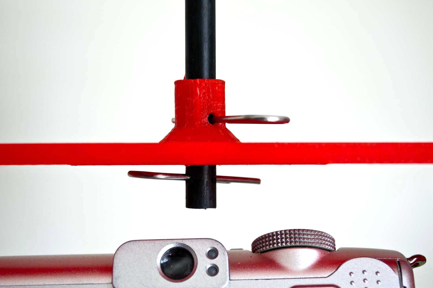
2. Mark the front-back position of the tripod
screw hole.
a. Hold the camera upside down and measure the distance from the center of the
camera’s tripod socket to the back of the camera body. If the lower part of the camera
is rounded, measure to the place the camera touches the tray lip when in position.
b. Measure on the top of the camera tray this distance (a) from the inside of the lip to
where the center of the tripod hole should be.
c. Mark the spot on the tray where the lengthwise and front-back positions of the tripod
socket meet. Mark it with a large plus so it remains visible after drilling starts.
d. Scratch a lead hole with a knife to get the drill bit started.
3. Drill the hole for the tripod screw.
a. Drill a hole with a small bit (~1/8”). The plastic has a low melting point and will
soften quickly during high speed drilling. Drill carefully because the bit will start to
“swim” through the plastic when it gets warm.
b. Enlarge the hole with the 1/8”drill bit and cut away any melted plastic. Place the
camera in its proper position on the tray and look through the new hole into the tripod
socket. If it looks like it is close to being centered on the tripod socket, proceed.
c. Enlarge the hole with a 13/64”drill bit. Clean up the hole and check again that it is
properly aligned by sighting through it from the bottom into the camera’s tripod socket.
d. Enlarge the hole until it is almost 1/4”diameter. The plastic is soft enough that this can
be done with the 13/64”bit and you can carve the hole closer or farther from the lip so
the camera will be snug against the lip when it is screwed on.
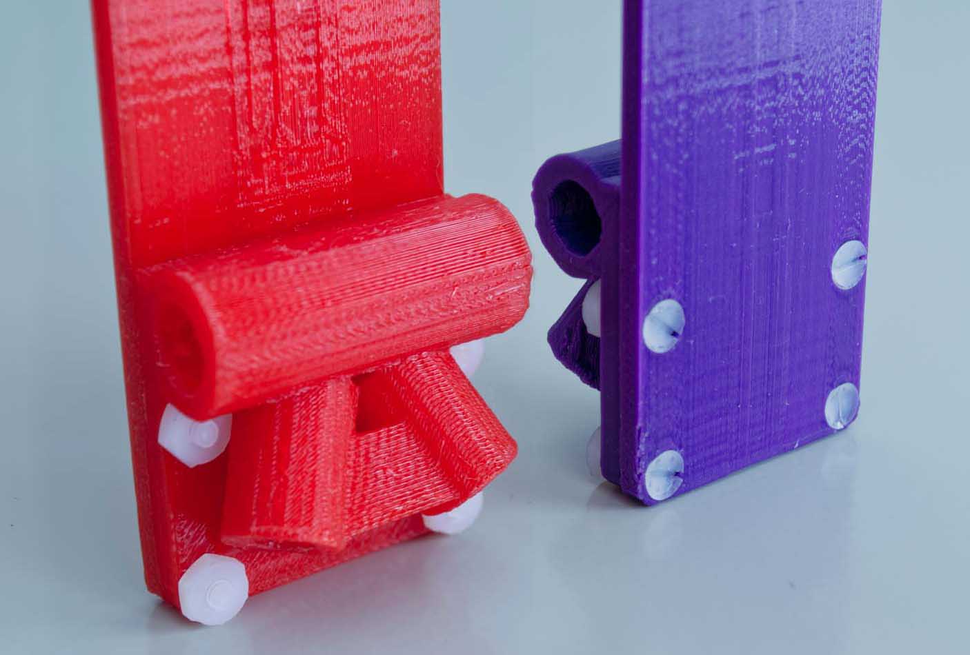
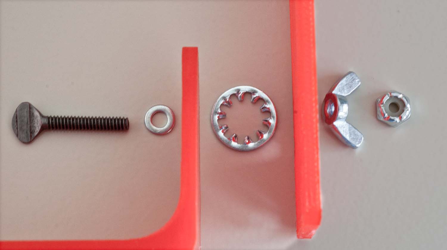
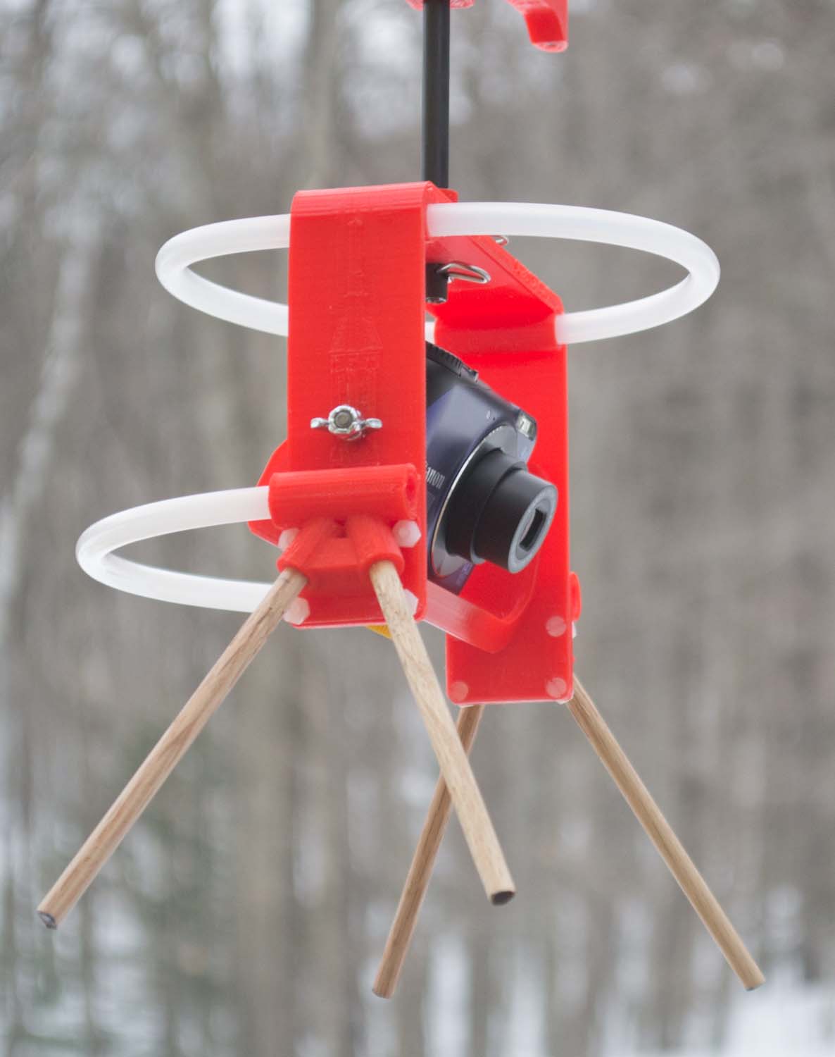
e. Try to insert the tripod thumb screw into the hole. The thumb screw must turn freely in
the hole before you try to thread it into the camera or you risk stripping the threads in
the camera’s tripod socket. Ideally, the screw will thread itself through the plastic, but
then turn freely when it is all the way in. This turning will strip the threads you just
made, but the screw will stay inserted in the tray when the camera is not attached. If
the hole gets too big for this, that’s okay.
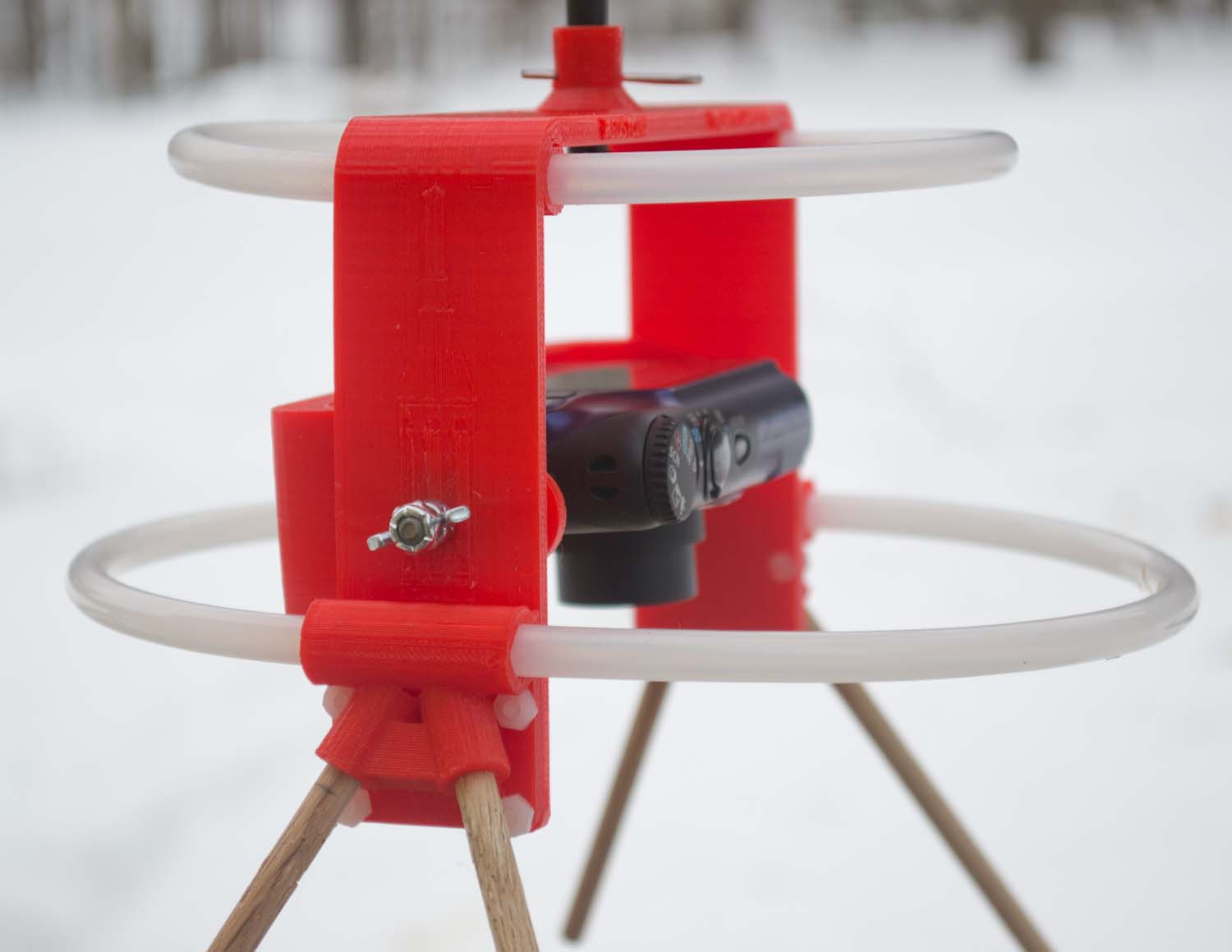
f. If the camera mounts too far from the lip, enlarge the hole toward the lip so the camera
can be screwed on snug against the lip. This is important so the camera cannot rotate
and begin to loosen the thumb screw (bad thing for flying cameras).

Page | 3
The camera tray is on the left, the upper frame
is on the right.
g. If the hole gets too big to hold the thumb screw, you can make the hole smaller again
by melting some plastic (PLA) with a soldering iron and adding material to the inside of
the hole. There is some PLA filament (or other shape) with your rig parts for this use.
Step 3. Attach camera tray to upper frame
1. The wide camera trays have a choice of three
holes for the thumb screw. Use the one which
allows your camera to balance best (front-to-
back) with the lens extended.
2. The large toothed lock washer goes between
the camera tray and the upper frame.
3. The wing nut and lock nut go on the outside of
the frame.
4. The nylon insert lock nut should be threaded
onto the end of the thumb screw just far
enough so the screw end is flush with the outside of the nut. It ensures that the wing nut
cannot fall off but allows it to turn freely for adjustment.
5. When assembled correctly with the large lock washer between the upper frame and tray, the
wing nut can be tightened by hand so that the weight of the camera will not change the angle
of the camera tray. Do not try to rotate the tray when the wing nut is tight, loosen it first.
Step 4. Configuring legs and bumpers
The traditional configuration is with four legs which protect the camera from dirt and wet grass during
setup and against hard landings. Additional camera protection can be added by attaching loops of
polyethylene tubing. Many configurations are possible with the included tubing, and it is easy to
make changes in the field.

Page | 4
Both cotter pins are required.
1. There are two sizes of tubing —the thicker one is only for leg loops to replace the oak dowel
legs.
2. The 5/16”tubing (the narrower size) should slide through the horizontal plastic tubes with
concerted effort. If the fit is too tight, use a blade to smooth the edges of the tube ends, or use
a 9/32”drill bit to ream the holes a bit. It is good to have a very tight fit.
3. Where the ends of a loop of tubing meet inside a horizontal plastic tube, insert a 1 inch (2.5
cm) piece of plastic or wood dowel in the ends to join the tubing more securely (3 pieces are
included).
4. To attach tubing loops instead of oak legs, insert a 1 inch (2.5 cm) piece of 1/4”oak dowel
into each angled leg bracket, then slide on the ends of a 26 cm long piece of 3/8”tubing (the
larger size). The tubing loops are better for balloon photography because they avoid hooking
the vertical balloon line as straight legs are wont to do.
5. For oblique photography, the lower horizontal bumper might be in the field of view. Therefore
that bumper is made from two pieces of tubing so half of it can be removed to clear the view
for the camera.
Step 5. Attaching the rig to a suspension system
1. The shaft for a Picavet or pendulum suspension
can be inserted into the vertical bracket at the
top of the frame.
1. If the shaft from the suspension is too tight inside
the bracket, smooth the upper and lower ends of
the plastic bracket tube with a blade or ream the
hole with a 5/16”drill bit. If the fit is too loose,
stick a piece of adhesive tape on the shaft.
2. A single hole should be drilled through the side
of the plastic tube for a cotter pin. This hole is
already present, but might need to be made
larger (7/64”drill bit).
3. When flying, always insert a second cotter pin below the frame. Don’t trust a single pin.
Step 6. Safe flying
Always secure the camera to the Redstone Rig with a lanyard. The wrist strap on point & shoot
cameras works well for this.
Caution: The large plastic parts of the Redstone Rig are 3D printed from poly lactic acid (PLA)
which will deform if it gets too hot. Don’t leave the rig in a closed car in direct sunlight on a hot day.
Table of contents
Other KAPtery Camera Accessories manuals