Karel DSS25 Use and care manual

02/2010
DIRECT STATION SELECT MODULE
TECHNICAL REFERENCE AND USER GUIDE

DIRECT STATION
SELECT MODULE
TECHNICAL
REFERENCE
AND
USER GUIDE
FEBRUARY–2010

DSS25–28 TTKK REV–AAA / 08.02.2010
KARELreservesthe righttomakemodificationsinproduct featuresmentioned
inthis documentfordevelopmentand improvementpurposes, withoutprior
notice.Individualproducts maypossess characteristics differentfromthosethat
havebeenmentionedinthis document, due totheir differencesinsoftwareand
hardwareversions.
Version Table
Software Version Date/Version of Guide
AAA 08.02.2010/AAA

DSS25-28

ISSUESTO PAY ATTENTIONTO
•Readthis guide carefullybeforeyouputyourdeviceintouseandkeepit
for later reference.
•Anymistakewiththeconnectionsinyourdevicemaydamagethe device
oryourexchange.Especiallytheconnection tothe exchange must be
made bythe Authorized TechnicalServices. The explanationsabout
connectionsinthe user’s guide havebeenincluded togiveinformation
only.
•Donotmakeanyconnection otherthan the CO connection tothe KAREL
telephone branchexchanges.
•Thereis no part thatyoucan repair ormaintaininyourdevice;therefore
call the authorized technical serviceincaseof anymalfunction.
•Keep your deviceawayfrom direct sunlight.
•Donot let anyliquidsubstancespill on your device.
•Dothe exteriorcleaning ofyourdevicewithaslightlymoistenedpieceof
cloth.
•Donot applyanychemicals for cleaning.
•Pleasecall yourauthorized resellerincaseyouwouldliketochangethe
placeofyour device. Useits ownpacking tocarryit.
•Pleasedo notuseexteriorsignalforthe test operationsormaintenance.
Anysignalwhichis used externallymaydamage your device.

PREFACE
The chapters inthis guidehavebeenprepared inordertopresentdetailed
technicalinformationtopeoplewho needtechnical-introduction-based
information aboutthe DigitalDSS25-28 Direct Station Select Module,and in
ordertogiveinformation aboutprogramminganduseofthis module.Bythis
way,one couldunderstandabilitiesofthe DigitalDirect Station Select Module,
howit is tobe operatedinaccordancewithcustomerdemandsand thingsthat
shouldbedoneinorder tooperatethe panes infull performance.
The modulehasbeen explainedasDSS withinthe guide,forthe sakeof
descriptivesimplicity.
The firstchapter-“TechnicalIntroduction”–It containsbasic information about
the structureof the Digital DSS25-28 Direct Station Select Module.
The second chapter–“Installation”–The methodstobe followed forthe
installationofthe DSS25-28 areexplained.This chaptermust definitelybe read
beforethe installationbythe personnelwho aretoperform the installation.
The thirdchapter–“Basic Structure”–This chapterexplainsthethingstobe
doneafterthe DSS25-28 Moduleis programmed.The chapteralsoincludes
information about useof the programmed keys.
The forthchapter–“KeyProgramming”–This chaptergivesbriefinformation
aboutthe softwarefeaturesthatwillenrichfunctionsofthe DigitalDSS25-28
Direct Station Select Moduleand thatcouldbe applied tomeetdaily
communicationneeds of customers morecomprehensively.
Best Regards,
KAREL

CONTENTS
TECHNICALFEATURES ..............................................................................1
INTRODUCTION .........................................................................................1
COMPATIBILITY..........................................................................................1
PARTS LISTONDELIVERY.....................................................................2
BASICFEATURES......................................................................................2
TECHNICALSPECIFICATIONS...............................................................2
GENERALAPPEARANCE.........................................................................3
INSTALLATION...............................................................................................4
BASICSTRUCTURE......................................................................................5
KEYPAD........................................................................................................ 5
LEDSTATUS............................................................................................... 5
UTILIZATION................................................................................................5
KEY PROGRAMMING ...................................................................................6
EXTENSION.....................................................................................................6
LINE ................................................................................................................ 6
EXECUTIVE KEY..............................................................................................7
PRIVATE POOL ...............................................................................................7
COMMON POOL ..............................................................................................7
FEATURE......................................................................................................... 8
FEATURE CODE.............................................................................................. 8

DSS25–28Direct StationSelect Module
1
TECHNICAL FEATURES
INTRODUCTION
DSS25-28 is the Direct Station Select ModuleofKARELanddesigned forST26,ST30
digitaltelephoneswithinthecontextofthe KARELDS Seriesexchanges. The aim of
this product is tomakeeasierforusertoaccess otherextensions, linesand some
featuresofthe exchange and alsousercanmonitorthe situation ofexchangesand
lines.
The digitalDSS25-28moduleenablestheusers toperform the functionaloperations,
aswell asproviding monitoring ofthe statusesoffunctionsthathavebeen assigned to
the keys, byasinglekeythroughits special-purposekeys and displayonit.
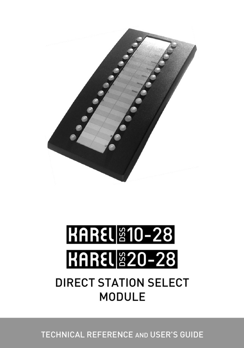
The DigitalDSS25-28Direct StationSelect Moduleconsists ofakeypadonly.The
keypadofthe DSS25-28 moduleconsists of28 programmable(14x2matrix)special-
purposekeysandthereis aLED foreachkey.The functionsthathavebeenassigned
tothe keyscanbe monitored through theLEDs onit. All ofthose28 keysareusedfor
assigningthe access codesand thereis no needtomakeanyprogrammingthrough
the DSS25-28 module.
COMPATIBILITY
The DigitalDSS25-28Direct StationSelect Moduleis compatiblewiththe entirerange
ofDS SeriesSystems. HoweverDSS25-28 moduleshouldbe used onlywithST26 and
ST30 Digital TelephoneSets.
Inorder tosupplythe continuityof regular operation, the hardwareversions ofthe cards
and thatwill beconnected tothe DSS25-28DigitalDirect StationSelect Moduleshould
be as the followings;
- The hardwareversionofEX200 (0/16U) DigitalExtension Moduleshouldbe ABF
or better,
- The hardwareversionofEX200 (0/8U) DigitalExtensionModuleshouldbeBAFor
better,

DSS25–28Direct StationSelect Module
2
PARTSLIST ON DELIVERY
Parts that comewithinthe packageof the Direct Station Select Module:
- DSS25-28 Direct Station Select Module
- Technical ReferenceandUser GuideCD
- AccessoryPackage for Telephone Connection:
- ConsoleConnectionCable
- Metal ConnectionPiece
- Fixing (Connection) Screws (4Units)
- Mounting Template
BASIC FEATURES
-The communicationbetweenSTdigitalphone and DSS moduleis an
asynchronous serial channel communication.
-DSS moduleis used the outputofthe digitalextension ofthe DS SeriesSystems
and directlyconnect tothe related STdigital phone set.
-Two-wirestructureis employed forthe communicationbetweenthe DSS and ST
phone set.
-Thereis no needtospecificallyintroducethe DSS moduletothe systemsothe
terminalnumbersetting is notrequired.DSS moduledirectlycommunicateswith
the system over the STdigital phone.
-All requiredprogramming forthe digitalDSS modulearemade throughthe
connected STdigital phoneand all settings aresavedtothis STphone.
TECHNICALSPECIFICATIONS
Weight: 440 g
Dimensions: Width: 112mm, Length: 229mm, Height: 52mm
OperationTemperature: 0-40 °C
Storage Temperature: -20+60 °C
Humidity: 10-%80

DSS25–28Direct StationSelect Module
3
GENERALAPPEARANCE

DSS25–28Direct StationSelect Module
4
INSTALLATION
The connection ofthe DigitalDSS25-28 Direct StationSelect Modulewiththe ST
DigitalTelephone Sets is provided overthe connection pointon theST26 and ST30
DigitalTelephone Sets. OnlyoneDSS modulecan beconnected toeachSTDigital
TelephoneSet. It is notpossibletooperatemorethanoneDSS25-28 moduleoverthe
sametelephone set.
DSS25-28 Direct Station Select Moduleis connected tothe DSS connection pointon
the ST26 and ST30 DigitalTelephoneSets withthe two-wireconnection cableincluded
indeliverypackage of the module.
Inordertomaintainthe physicalconnection betweenthe DSS25-28 moduleand theST
digitaltelephone sets, the metalconnectionpiece,whichis included inthe delivery
package, must be fixed withthe screws.

DSS25–28Direct StationSelect Module
5
BASICSTRUCTURE
KEYPAD
The keypadofthe digitalDSS28moduleconsists of28 programmablekeysin14x2
matrixstructure.
Sincethe programmingofkeysaredirectlymadethrough the connected STdigital
phone,thereis noneed tomakeanyprogramming orsettingovertheDSS module.All
required settings aremade throughthe ST26 and ST30 Digital Telephone Set.
LED STATUS
Eachof 28 keys onDSS28modulecanbe programmed for afunction and the status of
this function is shownwithared LED.
Inthe normaloperationmode, youcantracethe function status of the keys asgiven
below:
ExtensionStatus LED
On Hook Off
Busy Continuously On
Ringing Blinking
Parked Continuously On
Line Status LED
Idle Off
Busy Continuously On
Incomingcall Blinking
Parked Blinking fast
UTILIZATION
Therearesomefacilitiesfordifferentsituationsinordertousethe programmablekeys
on DSS28module.
It is enoughtopress the related programmed keytoactivatethe programmedfacility.If
an extensionorlinenumberis assigned tothe key,the callis started just bypressing
this key.During theconversation,if this keyis pressedagainthe call is puton hold.By
this way,theoperationslike“Conference”, “Call Transfer” and etc. can becarriedout
easily.

DSS25–28Direct StationSelect Module
6
KEY PROGRAMMING
Thereare28 programmablekeysandthe programming ofDSS25-28 moduleis made
directlyoverthe STdigitaltelephone setfromTelephoneSettings>KeyProgramming.
Keyswill be activated after exiting from programming mode.
Thesekeyscan notbe deleted onebyonehoweveranotherfeatureorextention orline
can be assigned tothosekeyswithoutanyerrormessage.All assignments tokeyscan
be deletedfrom TelephoneSettings>KeyProgramming >AutoSetting >Clear all.
Extension
You can reachanextensionyoucallfrequentlythroughasinglekeybyprogramming
her/his numberon that key.
♦PressKey: Press the keywhichis wanted tobeprogrammed.
♦Extension No: Then the “Extension No=”menu comestoview.Inthis menu,the
displaycursorenablesdataentry.Afterthe userenters theextension numberby
usingthe numeric keypad,s/he confirms the extension numbers/he hasentered
bypressing the “Accept” key.The usercan enteran extension numberwithat
most 8digits, whenawrong number is entered, systemwill giveanerror.
If entered numberis programmed toanotherkeybefore,the previouskeywillbe
deleted and newkeywill be programmed for that number.
Anextension numbercan be assignedtoasinglekeyonly.Afterthe programming
mode is exited and thosekeysarepressed,the extension thathasbeenstored onthe
keyis directlycalled.Inaddition tothe calling function,statusofthe extension,which
hasbeen programmed asthe first functionofthe programmablekeyscan beviewedby
the LED next toit.
Line
It enablesyoutoprogramaspecific line numberonakey.Bypressing thatkey,you
can access thelinethathasbeen programmed onthe keyand makeacall (provided
that it is vacant) and youcan access that number byasinglekey.
♦PressKey: Press the keywhichis wanted tobeprogrammed
♦LineNo: If adetermined line numberis enteredandconfirmed,then thatline
numberwill havebeenassignedtothat key.
The lines, whichexist on the system, shouldbe entered.Thesenumbers can be8digit
atmost. Aline access codecan beassignedtoasinglekeyonly.Afterthe
programmingmodehasbeen exited,upon pressing thosekeys, it is possibletoaccess
the programmed line,without pressing9.
Statusofthe line,whichhasbeen programmed asthe first functionofthe keycan be
viewedbythe LED next toit.

DSS25–28Direct StationSelect Module
7
Executive Key
Anyextension who diverts his/hercalls touser, canbe assignedtothatkey.Extension
whodiverts his/hercalls, couldbethoughtasexecutiveand prioritycan begiven tothe
incoming calls tothatexecutive.At thatsituation when useris on thephone,s/he can
easilynoticethat thereis an incoming call toexecutiveand s/he cananswer thatcallwil
asinglekey. Toprogram executivekey:
♦PressKey: Press the keywhichis wanted tobeprogrammed
♦ExecutiveNo: Enter the extentionnumberwhichis selected as executive.
Afterthe extensionnumberis accepted asexecutive,the message “Successful” will
appearefor 1secondandatone will beheard.
Note:
•Anextension canbe assigned tomorethan oneexecutivekey.Incaseofthe
busyness, if therearemorethanone incomingcalls atthe sametime,thosecalls
can be assigned tothe executivekeys starting from the last
•Differentextensionnumbers can beassigned todifferentkeysasexecutive.If
thoseassigned executivescall eachother, calls can notbe monitoredbythe
executivekeys.
PrivatePool
You can program9linenumbers, whichyou call most frequentlyonthe privatepoolof
your telephone.
♦PressKey: Press the keywhichis wanted tobeprogrammed.
♦Register no:Inthis menu,the displaycursorenablesdataentry.Here,entriesof
the indicesthatcouldbeassignedaredoneassingledigit inthe range 1-9.The
enteredindexis automaticallydetected and thenthe numberthatyou wouldliketo
be assigned tothe keyis prompted bythe“no=” menu.
♦No: Anydesired linenumbercouldbeentered.Instead ofentering9atthe
beginningofthe numbers whichareassigned,thosecalls will be madebyusing9
automaticly.Afterexiting the programming mode,when thesekeysarepressed,
the privatepoolnumber that has beenassignedtothe keyis directlycalled.
Common Pool
Linenumbers thathavebeen storedinthe common poolmemoryfieldswithnumber
000-499 bytheoperator caneasilybe assigned tothe programmablekeys.
♦PressKey: Press the keywhichis wanted tobeprogrammed.
♦Register No: Indicesthatbelongtothe linenumbers, whichhavebeen entered
intothe commonpoolofthe exchange,areassigned tothe programmablekeysby
this menu option.Afterexiting the programming mode,when thesekeysare
pressed,the common poolnumberthathasbeenassignedtothe keyis directly

DSS25–28Direct StationSelect Module
8
called.(The indicesshouldbe entered3digits ad “001”becauseofDS200
Exchange’s properties)
Feature
It providesmaking useofsomefunctionsthathavebeen definedinthe systemby
pressing asinglekey.Forexample,inorderforthe call requests coming toyoutoring
atsomeotherextension,you canpress the keythathaspreviouslybeen programmed
and enterthe numberofthe extension,towhichyou wouldlikeyourcalls tobe
forwarded.
Features arelisted below:
−FollowMeKey
−Call Back Key
−DoNot DisturbKey
−PhoneLock Key
−ConferenceKey
−Night Mode (onlyfor operator)
−MessageListen (if EVM moduleexists)
−Page Key
−Call Collect Key
♦PressKey: Press the keywhichis wanted tobeprogrammed.
♦Afterthat, the featureoptionsmenu is reached.The desired feaureis selected
fromthatmenu andit will beconfirmed bypressingthe “Accept” key.Then the
LED whichbelongstokey,willturnon.If desired featureis assigned before,this
action will not be accepted.
Feature Code
Anycode of8digits canbe assigned tothe programmablekeysbyusing this menu
option.
♦PressKey: Press the keywhichis wanted tobeprogrammed.
♦Code: This code maybe one,suchas85 (FollowMe)thatcouldbeapplied bya
user, one,suchas8389 (WakeUpservice)thatcouldbeapplied bytheoperator
orone,suchas877777(Entrytoexchange programming)thatcouldbe appliedby
the systemsupervisor. If the entered numberis noneofthese,then it is detected
as an extension number andthat extension is called whenever that keyis used.
NOTÊ: Formore informationaboutprogramming themodule, please lookat
theTechnical Referenceand User Guideof yourDigital STSeries Telephone.

02/2010
DIRECT STATION SELECT MODULE
TECHNICAL REFERENCE AND USER GUIDE
This manual suits for next models
1
Table of contents
Other Karel Control Unit manuals