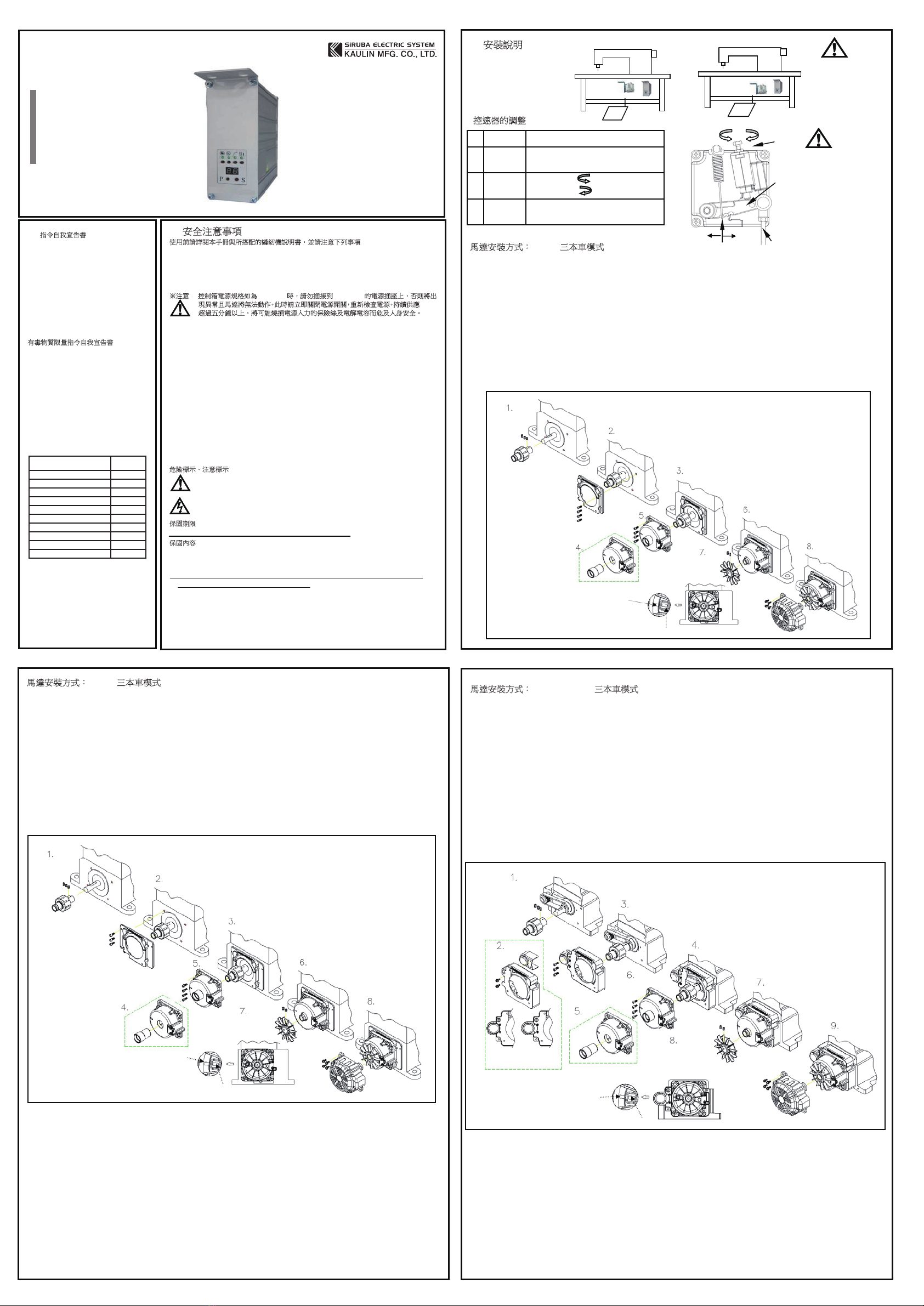
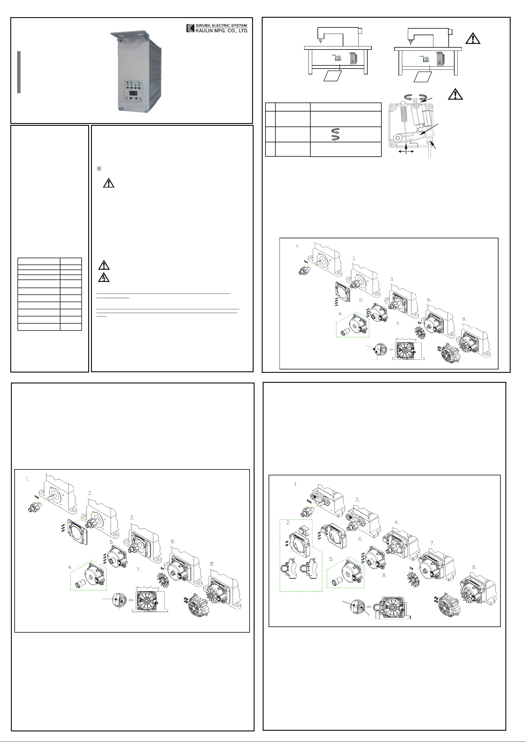
2. Installation:
Speed Control Unit Adjustment
Motor Installation-Sewing mode for cover stitch C007L
1. Take off the pulley of sewing machine and exhaust fan.
2. Connects motor shaft to sewing machine shaft, closes to original fan set.
Note: The red spot on motor shaft align to sewing machine surface or groove then uses set screws to fix.
3. Fix motor bracket on sewing machine.
4. Put assembly tool into motor then set assembly tool on motor shaft and push assembly tool to mot bracket then fix by set
screws. At last pull out the assembly tool.
Note: the magnet on motor shaft with strong attraction will cause hurt of finger or damage the motor. The assemble tool
must depose after used.
5. Put the fan into fan and push to end, screw tightly by set screws.
Note: before set the fan pleases turn sewing machine at top position and turn the fan to align to motor mark then screw
tight the fan, the motor stop at to position while it stops. Pleases release the fan to
adjust slightly to right position.
6. Sort out the motor cable and ahead of sewing machine then put fan cover to motor and fix it.
1. Safety Precaution :
Please read this manual with sewing machine manual thoroughly and pay attention
for the following safety precaution.
˙Installation and operation must be done by the trained personnel, also turn off the power switch and remove
the plug from outlet and wait for 5 minutes before any installation.
˙This product is designed for the specific sewing machines and must not be used for other purposes.
˙Only use the power voltage as described on the name plate of the motor and control box in ±10 % ranges.
※Attention : If the control box is AC 220V system, please don’t connect to the AC
380V power outlet, otherwise the error will occur and motor is not
functional. If that happened, please turn off the power switch
immediately and check the power voltage. Continue supply the 380V
power over 5 minutes might damage the fuses and burst the electrolytic
capacitors and even might endanger the person safety.
˙In order to prevent abnormal operation, keep the product away from the high frequency machines.
˙Don’t operate in direct sun light、outdoors area and the room temperature is 45°C above or 5°C under.
˙Don’t operate near the heater、dew area and the humidity is 30 % less or 95% more.
˙Don’t operate in dusty、evaporate、combustible gas area, and stay away from corrosive material.
˙Don’t apply heavy objects or excessive force on the power cord, also don’t bend or pull the power cord.
˙In order to prevent the static interference and current leakage, all grounding works must be done properly.
˙After power on the machine for the first time, use low speed to operate and check the correct rotation
direction.
˙During machine operation, don’t touch any moving parts.
˙All moving parts must have protective device to avoid the body contact and objects insertion.
˙Maintenance and repair must be done by the properly trained technician, also all the spare parts for repair
must be approved or supplied by the manufacturer.
˙Don’t use any objects or force to hit or ram the product.
Danger and caution signs
Limited Warranty
Warranty period of this product is 1 year from purchasing, or 18 months from our
manufacturing date.
Warranty Detail
Any trouble found within warranty period under normal use condition in conformance with this manual, it
will be repaired free of charge. Repair will be chargeable in the following cases even if within warranty
period :
1. Inappropriate use include: wrong connecting high voltage, wrong application, disassemble, repair,
modification by incompetent personnel, or operate the product without the precaution, or operate the
products out of its specification range. Insert odd objects or liquids into the product.
2. Damage by fire, Earth quake, lighting, wind, flood, salt corrosive, moisture, abnormal power voltage
and any other damage cause by the natural disaster or by the inappropriate environments.
3. Dropping after purchase, or damage in transportation by customer himself. (or by customer’s shipping
agency)
Note : We put our best effort and mind in testing and manufacturing for assuring the quality and reliable of
this product. But it is possible this product can still be damaged due to external magnetic interference
and electronic static or noise or unstable power source more than expected; therefore the grounding
system of operate area must be well-connected to this product and it’s also recommended to install a
failsafe device. (such as residual current breaker).
EC Declaration of Conformity
We hereby declare that the following products:
AC servo motor—HD62 series
are in conformity with the provision of the EC directives
as following :
-ECLow Voltage Directive (2014/35/EU)
-EC Electromagnetic Compatibility Directive
(2014/30/EU)
-EC Machinery Directive (2006/42/EC)
Applied harmonized standards :
EN 60204-31 : Electrical equipment of industrial
machines. Particular requirements for sewing
machines, sewing units and sewing system.
EN 12100: Safety of machines.
Declaration of Conformity for Concentration
Limits for Certain Hazardous Substances
We hereby declare that the following products:
AC servo motor—
are complies with the following directives and
requirements :
1. European Union RoHS Directive and the concentration
limits for certain hazardous substances
(2011/65/EU& (EU) 2015/863)
2. People’s Republic of China Electronic Business
Standard : Requirements for concentration limits for
certain hazardous substances in electronic information
products (SJ/T 11363-2006)
Our product itself (motor, control box) or its packing
materials and accessories (box, screws package, user
manual, sticker, label, print…etc.) or the suppliers of
parts and raw materials are all in conformity with the
provision of the European Union RoHS Directive and
People’s Republic of China Electronic Business
Standard to conform the following concentration limits
for the ten hazardous substances :
Hazardous Substance Permissible
Values
Lead0001)bP(
Mercury(Hg) 1000
Cadmium (Cd) 100
Hexavalent chromium (Cr VI) 1000
Polybrominated Biphenyl
(PBB) 1000
Polybrominated Diphenyl ether
(PBDE) 1000
Di(2-ethylhexyl)phthalate
(DEHP) 1000
Butyl Benzyl Phthalate (BBP) 1000
Dibutyl phthalate (DBP) 1000
Diisobutyl phthalate (DIBP) 1000
*The concentration of lead in the lead-free process for
PCB shall be less than 800 ppm.
*For packing materials shipped with our products or
parts, the hazardous substances shall be 80 ppm or
less insum of Pb+Hg+Cd+Cr VI.
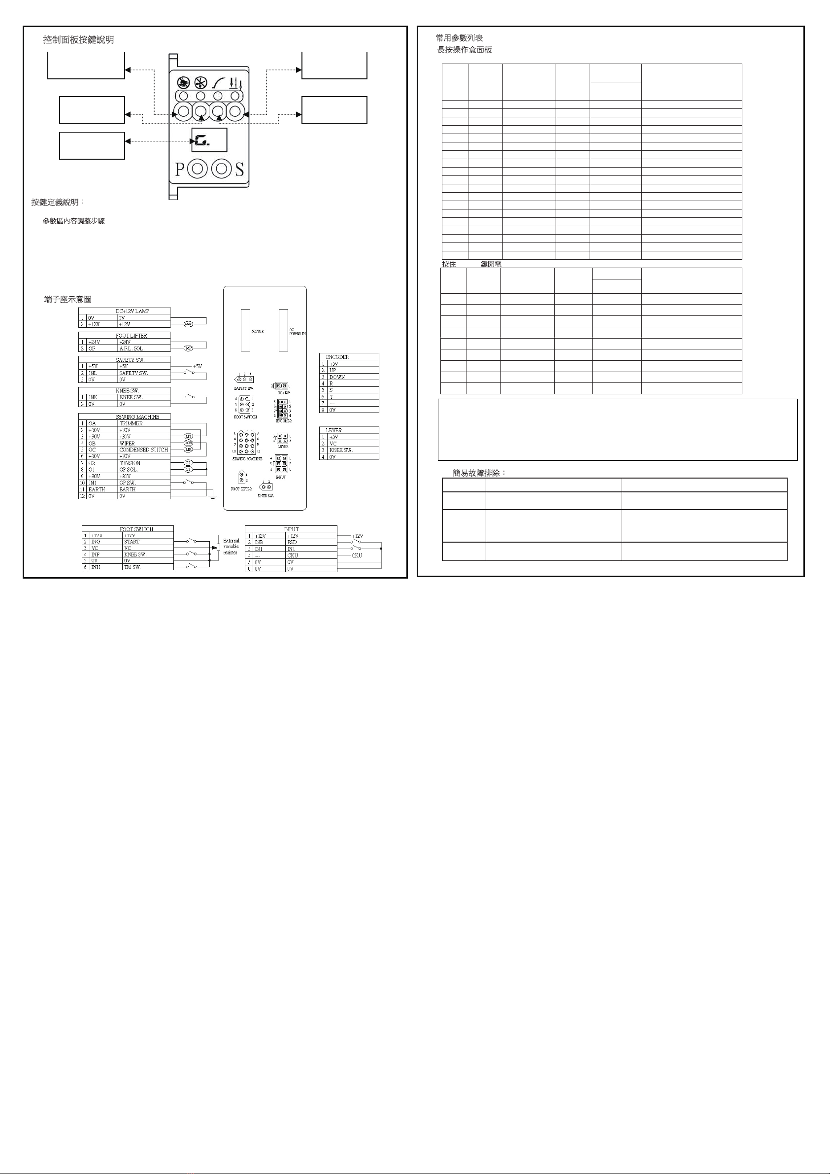
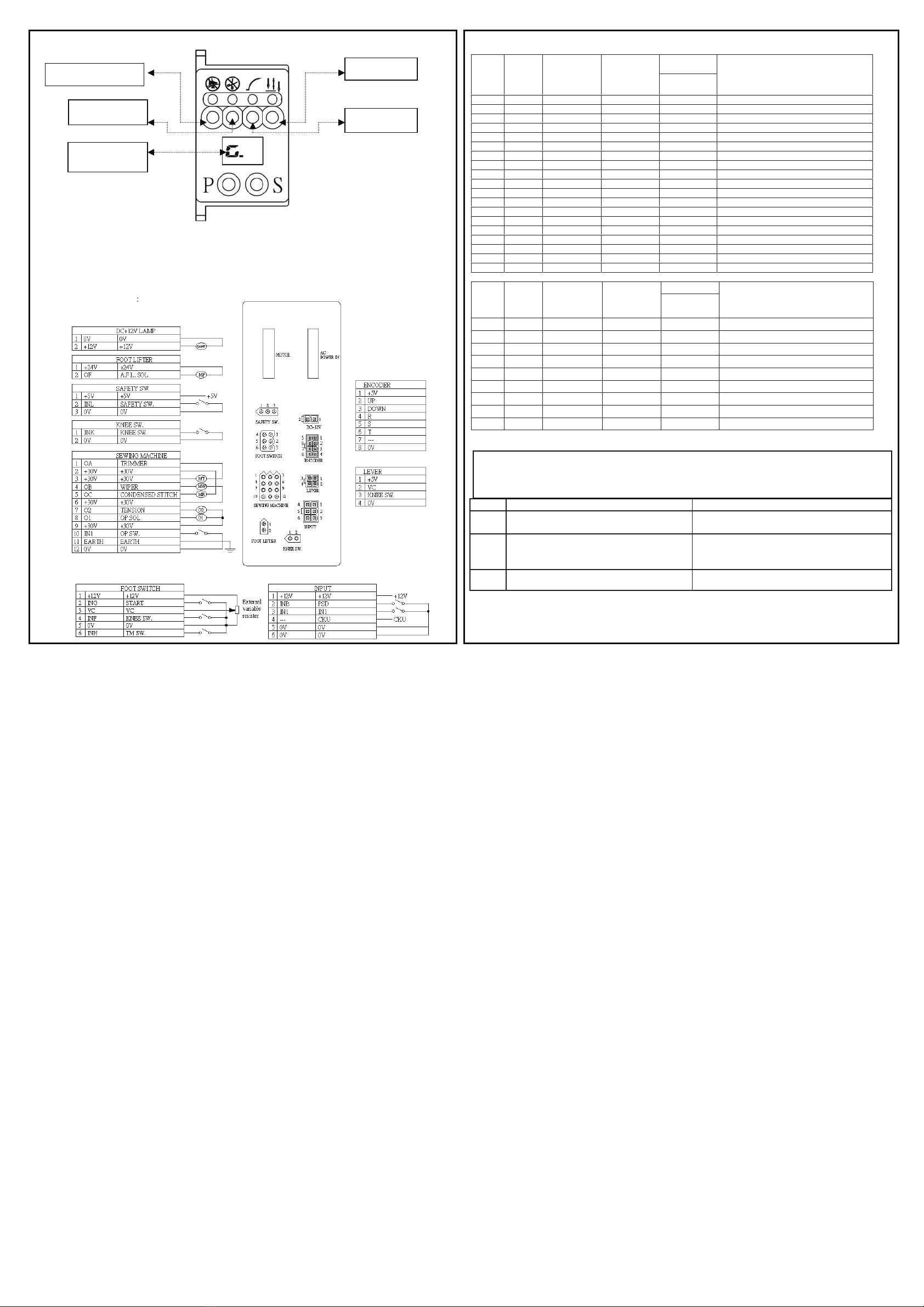
Caution :
Forperson safety, turn
off the power switch and
remove the power plug
from outlet before any
adjustment.
Risks that may cause personal injury or risk to the machine are marked with
this symbol in the instruction manual.
This symbol indicates electrical risks and warnings.
1
2
3
Term of adjustment
Toeing forward
force adjustment
Heeling backward
force adjustment
Pedal stroke
adjustment
Adjustment result
Spring A move to right = force increased
Spring A move to left = force decreased
Bolt B turn = force decreased
Bolt B turn = force increased
Rod Dsecure at right =stroke is longer
Rod D secure at left = stroke is shorter
Decrease Increase
B
C
D
Decrease Increase
A
Caution :
Forperson safety, turn off the power
switch and remove the power plug
from outlet before any adjustment.
Components of speed control
unit : see figure
A: Spring for toeing forward
force adjustment
B: Bolt for heeling backward
force adjustment
C: Pedal arm
D: Pitman rod forpedal
a). Install the motor and control box under the table. b). Install the pedal with speed control unit.
Assemble motor shaft,
the red spot of motor shaft
align the groove on
sewing machine.
Put assemble tool into motor
Motor with assembly
tool set on motor
shaft.
Turn sewing machine at top
position before assemble
the fan. Pull out the assembly
tool after
set the
fan.
Mark for motor
Mark for fan
Motor Installation-Sewing mode for cover stitch F007K
1. Take off the pulley of sewing machine and exhaust fan.
2. Connects motor shaft to sewing machine shaft, closes to original fan set.
Note: The red spot on motor shaft align to sewing machine surface or groove then uses set screws to fix.
3. Fix motor bracket on sewing machine.
4. Put assembly tool into motor then set assembly tool on motor shaft and push assembly tool to mot bracket then fix by
set screws. At last pull out the assembly tool.
Note: the magnet on motor shaft with strong attraction will cause hurt of finger or damage the motor. The assemble tool
must depose after used.
5. Put the fan into fan and push to end, screw tightly by set screws.
Note: before set the fan pleases turn sewing machine at top position and turn the fan to align to motor mark then screw
tight the fan, the motor stop at to position while it stops. Pleases release the fan to
adjust slightly to right position.
6. Sort out the motor cable and ahead of sewing machine then put fan cover to motor and fix it.
Motor Installation- Sewing mode for cover stitch C007K / C007J
1. Take off the pulley and fan on sewing machine, retain toothed pulley and belt.
2. Connects motor shaft to sewing machine shaft, closes to original fan set.
Note: The red spot on motor shaft align to sewing machine surface or groove then uses set screws to fix.
3. Assembles pulley cover. The pulley cover reserved 4 nuts uses to assemble mounting bracket for C007K or C007J.
4. Fix motor bracket on sewing machine.
5. Put assembly tool into motor then set assembly tool on motor shaft and push assembly tool to mot bracket then fix by
set screws. At last pull out the assembly tool.
Note: the magnet on motor shaft with strong attraction will cause hurt of finger or damage the motor. The assemble tool
must depose after used.
6. Put the fan into fan and push to end, screw tightly by set screws.
Note: before set the fan pleases turn sewing machine at top position and turn the fan to align to motor mark then screw
tight the fan, the motor stop at to position while it stops. Pleases release the fan to
adjust slightly to right position.
7. Sort out the motor cable and ahead of sewing machine then put fan cover to motor and fix it.
Assemble motor shaft,
the red spot of motor shaft
align the groove on
sewing machine. Motor with assembly
tool set on motor shaft.
Put assemble tool into motor
Mark for motor
Mark for fan
Turn sewing machine at
top position before
assemble the fan.
Pull out the assembly
tool after set
the fan.
Assemble motor
shaft, the red spot of
motor shaft align
the groove on
sewing machine.
Motor with assembly
tool set on motor shaft.
Turn sewing machine at
top position before
assemble the fan. Pull outthe assembly
tool after set
the fan.
Mark for motor
Mark for fan
Flat side of sewing machine
Illustrated of the pulley cover
assembly position.
C007K C007J
V groove of sewing machine
V groove of sewing machine
Assembles the heat shield
Assembles the heat shield
Assembles the heat shield
電控參數說明書
ELECTRONIC CONTROL
PARAMETER MANUAL
C007LD
C007K
S007K
C007JP
F007K