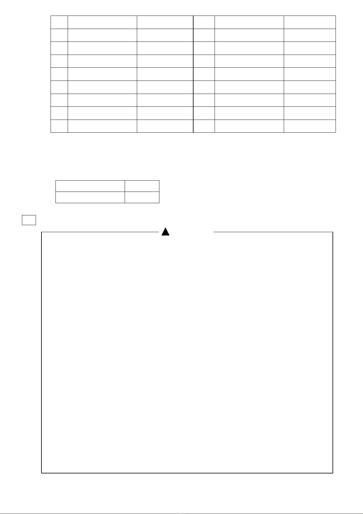
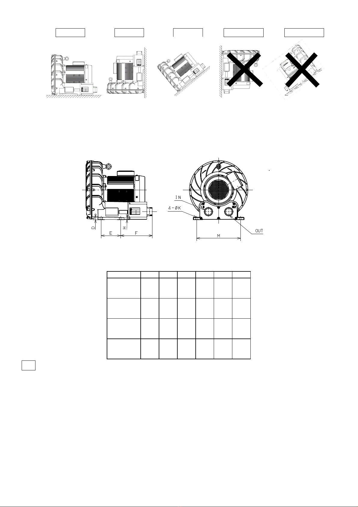
Kawamoto Pump Showa Denki U2G-70T User manual

― ―
Gust Blower U2G Type
Instruction Manual
(Original Instructions)
Thank you for purchasing the Gust Blower.
This instruction manual provides information for the customer to safely use this blower.
Always read this manual thoroughly and fully comprehend the contents before starting work.
Please keep this instruction manual in a handy place for quick reference.
< Contents >
‘1 Introduction ・ ・ ・ ・ ・ ・ 2 ‘7 Operation ・ ・ ・ ・ ・ ・ ・ ・ 12
‘2 Specifications ・ ・ ・ ・ ・ 2 ‘8 Maintenance and Inspection ・ ・ 15
‘3 Product Configuration ・ ・ 6 ‘9 Troubleshooting ・ ・ ・ ・ ・ ・ 16
‘4 Installation ・ ・ ・ ・ ・ ・ 7 ’10 Warranty ・ ・ ・ ・ ・ ・ ・ ・ ・ 18
‘5 Piping ・ ・ ・ ・ ・ ・ ・ ・ 9 ’11 Reference ・ ・ ・ ・ ・ ・ ・ ・ 18
‘6 Electrical Work ・・ ・ ・ 11 ’12 Disposal ・ ・ ・ ・ ・ ・ ・ ・ 18
1. This product must never be disassembled, repaired or modified by any person
other than a qualified repair technician. Improper repairs could result in electric
shocks or fires.
2. Always turn the power OFF, lock it, and make sure that power is not being supplied
before starting the maintenance service. Failure to observe this could result in electric
shocks or injuries.
3. Connect the ground wire properly, and install a dedicated earth leakage or disconnector
on the power supply side. Failure to observe this could result in earth leakages,
electric shocks or fires.
4. Do not touch the blower, motor or discharged air during operation. These sections
will be very hot, and touching them could result in burns.
Read the entire user manual l to be familiar with the features of this product before operating.
Failure to operate the product correctly can result in damage to the product, personal property,
and cause serious injury.
※ We will not be liable for any accidents if you do not comply with the above.
The precautions are classified as “Warning” and “Caution” to alert of the degree of injury or
damage that could occur if handling is mistaken.
In either case, these are important matters related to safety, and must be observed.
:Details which if ignored could lead to fatalities or serious injuries.
:Details which if ignored could lead to personal injuries or physical damage.
Special Notes
No -

― ―
1
Please check the following items upon receipt of the product.
If there are any problems, contact your dealer.
1. Confirm the upside of the package and open the package carefully. Failure to do may result in injuries.
2. Open with care, after check top and bottom. Failure to do may result in injures.
3. Check the nameplate to ensure that the correct blower has been delivered.
Check the type, output, voltage, frequency, etc. of the delivered blower in reference with the nameplate
to verify that the correct product has been delivered.
4. Check that no parts have been damaged during transportation, and that none of the bolts, nuts, etc.,
are loose. Tighten any part that is loose.
5. Check that all ordered accessories have been delivered.
6. Out of range use, Non-compliance with precautionary statements, improper repair or modification, installation
environment, Non-compliance with laws thing, accidental or intentional failure, replacement of consumable
parts, problem due to resale may not be covered by warranty.
7. When contacting us, check 「type」 and 「serial number」.
8. For disposal method of unnecessary parts and packing material, check with each local government.
2
●
Always use this blower within the specified product specifications. Failure to do so could result
in electric shocks, fires or air leaks, etc.
●The blower is manufactured for general industry use, and the discharged air is required to be clean.
Do not use it directly for applications (food, chemicals, semiconductor applications, etc.).
●
Select a product that matches the application. Using a product for an inappropriate application will
cause faults.
●
The danger. Warning and Caution labels indicate information on matters that could cause bodily harm
or property damage. Always observe the indicated information. Failure to do so could result in device
damage, electric shocks, fires or injuries, etc.
●
Do not use the air not mentioned as specifications. Failure to observe this could result in earth
leakages, electric shocks or fires.
●
When using for important equipment, prepare a spare blower.
Failure to observe this could result in shutdown of equipment and affect other equipments.
!
!
!

― " ―
2.1 Product specifications
Contents General air (free of explosive or corrosive gases)
Air Temperature -10~40℃
Humidity 90%RH or less (with no dew condensation)
Always use the blower Indoor in a location free of flammable gas or steam and at
an altitude 1,000m or lower.
Installation
location
Ambient
temperature -10 to 40°C (Use is not possible in sealed indoor area or in case)
Humidity 90%RH or less (with no dew condensation)
Installation requirements Horizontal with blower section facing downward (excluding U2G-370B series).
Noise level
[Under
ISO3744
condition]
U2G-70T 50Hz:61 dB(A) 60Hz:64.5[68.0] dB(A)
U2G-150 50Hz:65.5dB(A) 60Hz:68.5[75.6] dB(A)
U2G-370A 50Hz:67.5 dB(A) 60Hz:70.0[73.9] dB(A)
U2G-370B 50Hz:67.5 dB(A) 60Hz:70.0[73.9] dB(A)
Minimum airflow for
continuous
Use at least the minimum amount of air.
(Refer to sections 2.4、2.5 )
Motor
Type Totally enclosed fan cooled indoor type.
Phases 3phase
Voltage
200V Type 50Hz : 200V 60Hz : 200-220-230V
400V Type 50Hz : 380-400V 60Hz : 400-440-460V
(Note) For specifications other than those listed above, please check the delivery specifications.
2.2 How to read the model
2.3 Nameplate
No. 項目
① Type
② Code No.
③ Output (kW)
④ Frequency (Hz)
⑤ Voltage (V)
⑥ Current (A)
⑦ Rotation Speed (min⁻¹)
⑧ Power Factor
⑨ Efficiency (%)
⑩ Ball Bearing
⑪ Ball Bearing
⑫ Air capacity (m³/min)
⑬ Static Press (kPa)
⑭ Serial No.
⑮ Manufactured Date
⑯ Mass (kg)

― # ―
2.4 Table
Type U2G-70T U2G-150 U2G-370A U2G-370B
Output [kW] 0.75 1.5 3.7 3.7
Frequency [Hz] *1 50 60 50 60 50 60 50 60
Rated voltage [V] *2
200V class 200
200
220
230
200
200
220
230
200
200
220
230
200
200
220
230
Rated current [A]
200V class 2.6
3.6
3.4
3.3
5.9
7.5
7.1
6.9
10
13
12.3
12
12.3
16.3
15.3
15
Rated voltage [V] *2
400V class
380
400
400
440
460
380
400
400
440
460
380
400
400
440
460
380
400
400
440
460
Rated current [A]
400V class
1.3
1.3
1.8
1.7
1.7
2.9
3
3.8
3.6
3.5
4.9
5
6.5
6.2
6
6.2
6.2
8.2
7.7
7.5
Airflow [m
3
/min] 1.6 2 2.5 3.15 3.15 4 5 6.5
Static pressure [kPa] 6.2 7.8 7.2 8.8 9.8 12 8.5 10
Minimum airflow for continuous discharge
[m
3
/min] *3 0 0.1 0.2 1.3 0.8 1.6 1 2.7
Minimum airflow for continuous suction
[m
3
/min] *3 0 0 0 0 0 0 0.7 1.5
Approx. weight [kg] 22.5 33 48 55
※1:Within -5~+3% rated frequency at motor. ※2:Within ±10% rated voltage at motor.
(Note) For specifications other than those listed above, please check the delivery specifications.
Type U2G-70TC U2G-150C U2G-370AC U2G-370BC
Output [kW] 0.75 1.5 3.7 3.7
Frequency [Hz] *1 50 50 50 50
Rated voltage [V] *2
200V class 200 200 200 200
Rated current [A]
200V class 2.6 5.9 10 12.3
Rated voltage [V] *2
400V class 380 380 380 380
Rated current [A]
400V class 1.3 2.9 4.9 6.2
Airflow [m
3
/min] 1.6 2.5 3.15 5
Static pressure [kPa] 6.2 7.2 9.8 8.5
Minimum airflow for continuous discharge
[m
3
/min] *4 0 0.2 0.8 1
Minimum airflow for continuous suction
[m
3
/min] *4 0 0 0 0.7
Approx. weight [kg] 22.5 33 48 55
※1:Within -5~+3% rated frequency at motor. ※2:Within ±10% rated voltage at motor.
(Note) For specifications other than those listed above, please check the delivery specifications.

― ―
Type U2G-70TU U2G-150U U2G-370AU U2G-370BU
Output [kW] 0.75 1.5 3.7 3.7
Frequency [Hz] *1 60 60 60 60
Rated voltage [V] *2
200V class
208
230
208
230
208
230
208
230
Rated current [A]
200V class
3.4
3.2
6.9
6.4
11.5
11.0
16
15
Rated voltage [V] *2
400V class 460 460 460 460
Rated current [A]
400V class 1.6 3.2 5.6 7.5
Airflow [m
3
/min] 2 3.15 4 6.5
Static pressure [kPa] 7.8 8.8 12 10
Minimum airflow for continuous discharge
[m
3
/min] *4 0.1 1.3 1.6 3.3(208V)
2.7
Minimum airflow for continuous suction
[m
3
/min] *4 0 0 0 1.5
Approx. weight [kg] 22.5 33 48 55
※1:Within -5~+3% rated frequency at motor. ※2:Within ±10% rated voltage at motor.
(Note) For specifications other than those listed above, please check the delivery specifications.
※4:Minimum airflow for continuous
2.5 Outline drawing
$%
Minimum airflow for continuous use
Continuous use possible
at solid line

― & ―
3
10 1
2
4
14 15
13 12 11
5
8
9
7
6
※Caution label
3
'
3.1 Structural drawing

― ―
No.
Name Material No. Name Material
1 Bearings ― 9 Bolt SWRM
2 Bearings ― 10 Casing cover FCD500
3 Motor bracket FC200 11 Support SPCC
4 Casing ADC12(AC4A) 12 Sound absorbing material PUR(MF)
5 Spacer C2801P 13 Case cover ADC12(AC4A)
6 Impeller ADC12(AC4A) 14 Fan PA
7 Impeller washer SPCC 15 Fan cover SPCC
8 Washer with outer claw SPCC
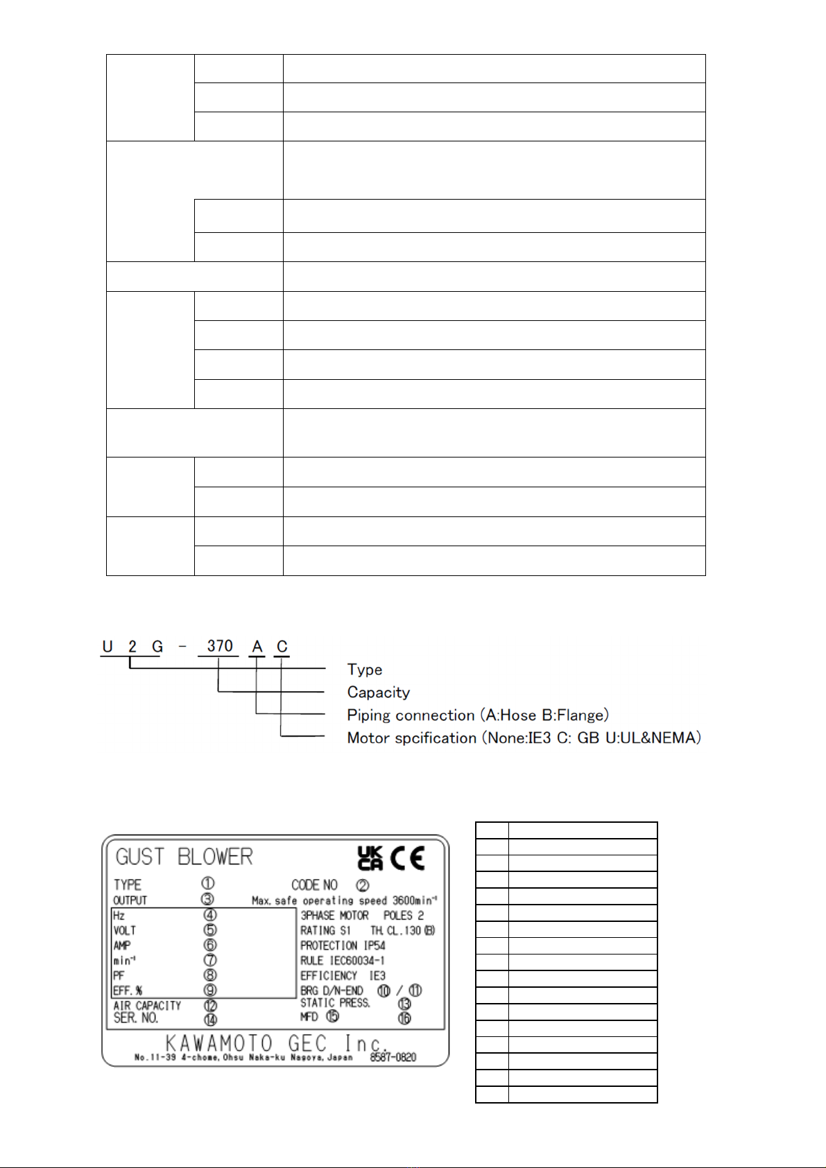
(Note) The specifications and structure, etc., are subject to change without notice.
※( ) is for U2G-370B series.
3.2 Standard attachment
Name Q’ty
Instruction Manual 1
4
$$
●Before hoisting the blower unit during unloading, loading, and installation, check the product
catalog, the installation drawing, and instruction manual, etc., to verify the blower unit weight
and the hoist method. Do not attempt to hoist a blower unit that exceeds the hoist’s rated
load. Incorrect hoisting can result in drops or injuries.
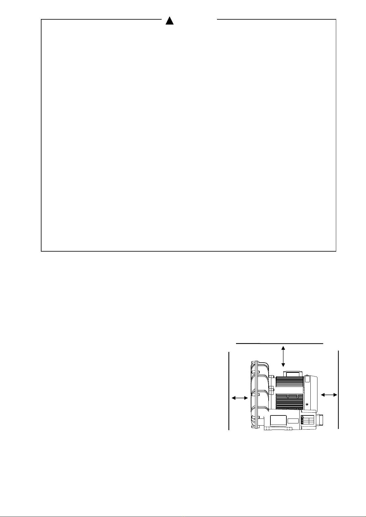
●Security install the blower as explained in the instruction manual. Install the blower horizontally
and secure it with bolts. Improper installation could result in electric shocks, fires or injuries
from dropping.
●Install the product according to applicable laws and regulations (Electrical Installation
Technical Standards, Wiring Regulations). Failure to do so is not only illegal, it may result in
air leaks, electric shocks or injuries.
●Do not install in places such as machine or chemical plants where harmful gases from acids,
alkalis, organic solvents, or paints, or gases containing corrosive elements are produced, or in
dusty locations. Failure to observe this could lead to earth leakages or fires.
●Do not incinerate resin and rubber parts on site.There is a risk of generating harmful gas.
Please check with each local government for the processing method.
●In consideration of the device life, make sure that the area around the equipment is well
ventilated. Select a place that is free of dust, corrosive or explosive gas, salt, moisture, steam,
and dew condensation, and where the product protected from wind and rain or direct sunlight.
A poor environment could degrade motor or control panel's insulation, etc., and can cause
earth leakages, electric shocks or fires.
●Do not use in an explosive atmosphere. There is a risk of fires.
!

― ―
●Do not apply impact on the devices, or tilt over. There is a risk of damage.
●Prepare a spare blower in case the blower stop working. Equipment may stop working.
●Screw the companion flange into the piping after removed from the blower. There is a risk of damage.
●Do not place objects or people on top of the device. There is a risk of injuries or damage to equipments.
●Please install a warning buzzer or the like in case of a malfunction so that you can check the situation.
If a malfunction occurs, it may lead to a serious accident before you know it.
●Install in the place of altitude 1,000m or less. It may result failure and risk of cannot function
properly.
●Tighten certainly in the screw part of piping using seal adhesive. Failure to observe this could
result in air leaks.
●Always clean the area before starting installation or inspection, etc. There is a risk of injuries
from slipping or tripping, etc.
●Please install the piping as below. There is risk of cannot function properly.
・As short as possible, reduce bending points.
●Do not install in location where there are obstacles that may obstruct ventilation for motor cooling.
It may cause damage, burnout, or fire.
●When installing a terminal box cover, be careful not to get your fingers caught.
Failure to do so may cause injuries to fingers.
●When unpacking, be careful of needles and staples. There is a risk of injuries.
●Do not cover the product with the plastic bag from the packaging. There is a risk of suffocation.
4.1 Installation
1.Select the location below for installation.
・ Flat and strong place with no irregularities.
(Place with external vibration acceleration about 6.9 m/s (0.7G) or less).
・ Well ventilation location, not exposed to direct sunlight and any liquid.
・ The place that the ambient temperature around motor does not exceed 40℃.
・ The place that you can clearly read the product nameplate.
(Do not remove the nameplate)
・ The space required for maintenance and inspection.
(Install the product 30mm or more away from walls and
ceiling.)
(Please open one side.)
2.Wear appropriate protective equipment such as helmets and
gloves when working.
3.When transporting the blower by hanging it, attach the hook to
the eye bolt on the main body, or use a nylon sling.
Be careful not to injure yourself when carrying by hand.
!
!

― ( ―
4.Installation direction
Acceptable Acceptable Acceptable Not acceptable Not acceptable
※U2G-370B series is horizontal only.
5.When installing, make sure to fix it using the mounting holes in the blower securely.
Dimensions for installation is as follows.
5
'
5.1 Piping
1.Install piping supports so that the piping’s load is not applied directly onto the blower.
2.Secure a flexible hose or pipe length of 1 m or more.
Do not put fingers in the discharge or suction port while driving. There is a risk of injuries.
3.Attach a special accessory or a commercially available air filter to the discharge and suction port.
Do not inhale the release powder of the sound absorbing material. There is a risk of suffocations or
damaged.
(Note) If the piping is long or thin, or has many bents or obstacles, the static pressure and air volume will drop.
TYPE D E F H K M
U2G-70T
U2G-70TC
U2G-70TU
U2G-150
U2G-150C
U2G-150U
U2G-370A
U2G-370AC
U2G-370AU
U2G-370B
U2G-370BC
U2G-370BU
14
18
159 12 12 225
14 115 187 12 15 260
95
202 15 15 290
15 140 146 15 15 300
140

― ―
)*
+$,*$-
'
..$/
4. Connection
For hose
Select a flexible hose that can withstand the blower pressure.
The temperature on the discharge side will be high depending on the amount of air used,
please use a pipe made from metal or high heat resistance.
For threaded piping
Fix the piping with suspension fittings or brackets, etc., so that the weight of the pipe or external
loads is not applied on the blower connection.
'
..$$
)*
+$,*$-
..$$
+$
'
'/

― ―
6
0$$/
●The electrical work must be completed according to the local regulations. Improper writing
and connections could lead to earth leakages or fires.
●Always earth the device before turning the power on. Do not connect the earthing wire to
gas pipes, lightning rods, or telephone earthing wires.
●Install a dedicated earth leakages circuit breaker and overload protection device on the power
supply side. Failure to observe this could result in earth leakages, electric shocks or fires.
●Avoid multiple connections (connecting multiple electric devices) and carry out installation
using dedicated wiring. Failure to observe this could result in earth leakages, electric shocks or
fires.
●After work, return the terminal box cover to original position. Failure to observe this could
result in electric shocks or fires.
●Clean off any dust from the power plug, wiring connectors, connections and terminals.
An electrical discharge on dust could cause heating or fires.
●Confirm whether a wiring joint and a connection part become loose or disconnected.
If it loose or disconnected on point, failure to observe this could result in electric shocks or fires.
●Refer to the connection diagram inside the terminal box or this instruction manual for power
cable connection. Incorrect wiring could result in electric shocks or fires.
●Do not install a power cable and control cable in the same pipe or duct. Failure to observe
this could result in trouble at this blower or other equipment.
6. 1 For standard voltage products, see the drawing on the below and connect the motor terminals to
the power supply terminals correctly.
IE3 and GB3 specification UL&NEMA specification
(Note1) UL&NEMA specifications have 9 terminals (T1, T2,T3, T4, T5, T6, T7, T8, T9).
(Note2) The nominal size of crimp terminals with UL&NEMA specifications is 1.25-4.
!
!
!

― ―
6.2 Always connect the protective conductor to the terminal with the following symbol:
6.3 The wiring should refer to local regulations.
6.4 For the selection of RCDs, refer to "2.4 Specifications" or the rated current value on the nameplate.
6.5 Please contact the place of purchase for the selection of overload protection devices.
Blowers have a longer start-up time than general rotating machinery, so the starting current
The overload protection device may be triggered by the starting current.
6.6 The Blower does not have a main switch.
Install a main switch that can be locked in the off position.
7
!
●Always turn the power OFF, lock it, and ensure that no power is being supplied to the blower when
attaching or disconnect wiring. Failure to observe this could result in electric shocks.
●Do not touch the live parts of the control panel, motor terminals, cable tips,
etc. after turning on the power or while the power is on. Failure to observe this could result in electric
shocks, short circuit or fires.
●Do not splash water into the motor. Failure to observe this could result in electric shocks,
short circuit or fires, and malfunction.
●In case of a power outage, turn off the power switch and lock it in the off position.
When the power is restored, there is a risk of product damage,
or the blower may suddenly start operating and may cause injury.
●Do not bring hands and foot close to a suction port during operation. Failure to observe this
could result in injuries by being inhaled.
●Do not use or perform work while the product is suspend. There is a risk dropping and injuries.
●Do not touch power supply or operation switch with wet hands, after turning on the power.
Failure to observe this could result in electric shocks or injures.
●Do not use this product out of the rated voltage. Failure to observe this could result in fires
or electric shocks.
●Confirm that the rotation direction is correct. Operating with the incorrect rotation direction
could cause the bolts to loosen from vibration, etc., and result in accidents.
●Do not touch the rotating areas during operation, and do not insert fingers or rods, etc., into
the motor openings. This could cause electric shocks or injuries.
●Do not touch blower or motor during operation. The motor could reach high temperature and
lead burns.
●Turn the power OFF, lock it, when not using the blower for long periods of time. Failure to observe
this could result in earth leakages, electric shocks or fires due to deterioration of the insulation.
!
!
!

― " ―
12-$
'
3$4
56$/7
●Do not place flammable objects near the blow. Failure to observe this could result fires if a
power plug generates heat and ignites.
●When resuming operation after a long-term storage or suspended, refer to the "Installation"
and "Operation" sections and perform trial operation. The blower could be lock and the motor
burnout if parts are stuck, etc.
●Operate the blow within the specification. This could result damage to the blower if operates
out of specification range.
●Do not use the product over the rated frequency when driven with an inverter.
Failure to observe this could result in the blower burning out or fires.
When operating the motor with a 400V class inverter, install a suppression filter or reactor on
the inverter side, reinforce the motor side with insulation. Failure to observe this could lead to
damage or fires due to insulation breakage.
●Do not throttle the amount of air below the minimum amount of air that can be discharged and
used continuously. Failure to observe this could result in injuries or burns.
7.1 Trial operation
1.Verify that the earth leakage breaker capacity, the power supply voltage, and the wiring are correct.
2.Confirm that no objects are placed around the suction port and discharge port. The blower could
be damaged if foreign matter is inadvertently sucked in.
3.Turn the power ON, and confirm the rotation direction of the motor is suitable for your machine.
If the rotation is reversed, turn power OFF, lock it, then replace the connections of 2 of
the 3 wires.
4. Confirm that air is discharged from the discharge port. Confirm that there are no problems such as
pressure, current, vibration or noise.
7.2 Operation
1.On the discharge side, continuous operation is possible up to the minimum airflow for continuous use
listed in section 2.4. If there is a risk of exceeding this range, be sure to provide a bypass hole in the middle
of the piping.
!
!
--

― # ―
120
100
80
60
40
20
0
0
1
2 3 4 5 6
120
100
80
60
40
20
0
0
1
2 3 4 5 6
3$4
56.7
'
2.When using air intermittently,
recommended to use the changeover valve on the top of the pipe..
When using air by starting and stopping the motor, limit the sequence to max. 15 times/hour.
4*$
3.Note that the discharge air temperature will increase according to the amount of air being used.
Discharge air temperature rise curve
'
1$%
!
8
-44$4
-44$4
1$%
&)9
)9
$%
5.
"
:
.7
$%5.
"
:.7
.
5℃7
.
5℃7
;"
;
;
;"
;
;
12-$
-
;"1 ;"1
.
5℃7
.
5℃7
$%
5.
"
:
.7
$%
5.
"
:
.7
)9
&)9

― ―
(Note1)The value obtained by adding the suction air temperature is the discharge air temperature.
(Note2) Continuous use is possible only at the solid line section ( ).
4.Observe the inverter manufacturer's EMC instructions when using the inverter as described below.
・The airflow can be freely adjusted even during variable speed operation with the inverter.
Operate at a frequency of 20 to 60Hz, and a current lower than the rated current value.
・The noise level may increase depending on the type of inverter.
In addition, the peak voltage can damage the motor. Installing an LC filter you can prevent the
increase noise level and peak voltage.
・The applied voltage contains harmonics instead of sine waves.
Depending on the type of inverter, it may heat the motor.
8
<
●If the blower does not operate or if an abnormality is found (such as a torn cable or burning smell),
stop operation immediately and turn the power OFF, lock it. Then the contact the place of purchase
or a designated service center for inspections and repair. Failure to observe this could result in
electric shocks, fires or air leaks, etc.
●Always turn the power OFF, lock it, and ensure that no power is being supplied to the blower before
starting maintenance servicing. Failure to observe this could result in electric shocks or injuries.
●The product must never be disassembled, repaired or modified by any person other than a qualified
repair technician. Improper repairs could lead to electric shocks, fires, or air leaks.
●If insulation resistance value reduce 1MΩ or less, contact the place of purchase or a designated
service center. There is a risk of electric shocks or air leaks.
●Always use genuine our company parts for repairs. Use of non-genuine parts could cause faults and
accidents. In addition, proper functions may not be achieved.
●Do not touch power supply or operation switch with wet hands, after turning on the power.
Failure to observe this could result in electric shocks or injuries.
●When resuming operation after a long-term storage or suspended, refer to the "Installation"
and "Operation" sections and perform trial operation. The blower could be lock and the motor
could burn if parts are stuck, etc.
●Both periodic inspections and daily inspections are both recommended to ensuring safe use for a
a long time. Failure to perform inspections can result in blower faults and accidents. Contact with
your dealer or nearest Kawamoto Sales Office for periodic inspections.
●Periodically check protective contactor. If it does not normality, there is a risk of electric shock
or failure.
●Periodically replace the consumable parts. Using the blower with degraded or worn parts can result
in air leakages, burning or damages. Contact with your dealer or nearest Kawamoto Sales Office
for periodic inspections and part replacement, etc.
●When using pressure or vacuum gauge, closing the valve to expect when measuring. If always opening,
failure to observe this could result in failure.
●Make sure to perform inspections according to the inspection items. Malfunctions may not be
prevented and may lead to accidents.
!
!
!

― & ―
Please check the following inspection items from time to time, and perform maintenance and replace
consumable parts as necessary. Wear appropriate protective equipment such as helmets and gloves
when working.
8.1 Daily inspection
Check item Failure criterion
Noise value/vibration No change from the time of installation.
In order to discover abnormalities early, it is important to get to know a daily change.
We recommend to keep journal operation diary for that purpose.
8.2 Periodic inspections
Check item Contents
Motor surface Dust or oil, etc., adhering to the surface are cleaned.
Blower section Check whether the air performance has dropped.
Be careful when using solvent or similar to clean the blower. Inappropriate use of solvent may result
in poisoning. Futhermore, thinner and/or benzene may change or discoloration of blower painting.
8.3 Consumable parts
The following parts are consumable parts.
Please request the replacement of parts by referring to the guideline for replacement.
Parts name Replacement frequency
Estimated condition
Bearing 2 years When generation of heat noise, and unusual
vibration occur.
Sound absorbing
material 2 years When the noise increases, or when the sound
absorbing material has hardened or deformed.
・If abnormal in daily maintenance and check, we will recommend you repair a little early.
・If the sound absorbing material degrades, particles that peel off could be discharged to the
secondary side of the blower.
9
*$-
● If the blower does not run, or if there are any abnormalities, stop operation immediately and
turn the power OFF, lock it. Contact your dealer or designated service center for inspection
and repairs.
●Always turn the power OFF, lock it, and ensure that no power is being supplied to the blower
before starting maintenance service. Failure to observe this could result in electric shocks
or injuries.
●The product must never be disassembled, repaired or modified by any person other than a qualified
repair technician. Improper repairs could lead to electric shocks, fires or air leaks.
When there are any abnormalities after carrying out the check item of the following table,
!

― ―
Please contact your dealer or designated service center.
Problem Cause Countermeasure Refer
page
Blower does not
run.
The short circuit breaker is OFF. Check the switch and power circuit. -
Power supply problem. Inspect and repair. -
The blower id connected with a
single-phase connection. Correct the wiring. 29
Impeller is clogged with foreign
matter. Contact your dealer. -
Motor rotates,
but no air is
discharged.
Blower rotation direction is
reversed. Correct the wiring. 29
Impeller is clogged with foreign
matter. Contact your dealer. -
Pipe is clogged with foreign matter.
Air is leaking from the pipe.
Inspect inside the pipe, and remove the
foreign matter.
Inspect the pipe and tighten the
connection.
-
Parts are worn out. Contact your dealer. -
The pressure loss in the pipe is high.
Review piping. -
Overload(over-
current) occurs.
Voltage is too low or unbalanced. Adjust voltage. -
The bearing of a motors is worn out
or damaged. Inspect and repair. -
The operation exceeds the minimum
airflow for continuous discharge. Review the working airflow. 22,23
There is vibration
or abnormal
noise.
Installation defect. Check of an installation state. 26,27
Impeller is clogged with foreign
matter. Contact your dealer. -
The bearing of a motors is own
our or damaged. Inspect and repair. -
・Unexpected trouble could occur, however it is important to take appropriate measures
immediately when an abnormal condition is found.
・If the cause of the problem is not clear, contact your dealer or designated service center.
When contacting us, please inform us of the product model, serial number, and failure (abnormality)
situation.

― ―
10
2
10.1 Scope of warranties
If the product malfunctions within the warranty period when used in accordance with the instructions in
the instruction manual, labels attached to the product, etc., we will repair it free of charge.
However, if this product is incorporated into the customer's equipment, the cost of removing it from the
equipment, installing it on the equipment, etc., and other incidental construction costs, transportation
costs, etc., and the opportunity loss caused to the customer, operational losses and other indirect
damages are not covered by the warranty.
We will not compensate for damages caused by defects that occur while using this product.
10.2 Term of warranty
The warranty period is 1 year from the date of delivery.
Even within the warranty period, repairs will be charged in the following cases:
1. Malfunctions and damage caused by incorrect use other than those described in the instruction
manual/precautions
2. Failure or damage caused by unreasonable repair or modification (including drilling holes in the product)
by a party other than our company
3. Failure or damage due to dropping, transportation, etc. after purchase
4. Failure or damage caused by fire, earthquake, wind and flood damage, lightning, other natural disasters,
abnormal voltage, unspecified power source (voltage, frequency), etc.
5. Failure or damage caused by using parts other than those specified by our company
6. Malfunctions and damage due to foreign matter contamination
7. Defects such as discoloration, scratches, natural wear and tear of consumable parts due to aging or
use
11 Reference
For inquiries regarding this product, please contact your nearest Showa Denki Co., Ltd. sales office.
When requesting a problem or repair, please contact us with the product name (TYPE), manufacturing date
(MFD), and serial number (SER. NO.) written on the nameplate.
12 Disposal
Please follow laws and regulations when disposing of the product.
.5 ='07
.5<+>7
$.*50!7
(Note) Please check
our website for the
latest information on
sales offices.
List of sales offices

― ( ―

― ―
This manual suits for next models
11
Table of contents
Popular Blower manuals by other brands

Garland
Garland GAS 800 MG-V18 instruction manual

Electrolux
Electrolux Sanitaire SC6053A owner's manual

Vortex
Vortex Ranger 1000 instruction manual

Hitachi
Hitachi RB24E Handling instructions

Xtreme Garage
Xtreme Garage PB-40001G operating manual

Spear & Jackson
Spear & Jackson SPJBV 3200 operating instructions