kawneer.com
Laws and building and safety codes governing the design and use of glazed
entrance, window, and curtain wall products vary widely. Kawneer does not control
the selection of product configurations, operating hardware, or glazing materials,
and assumes no responsibility therefor.
Kawneer reserves the right to change configuration without prior notice when deemed
necessary for product improvement.
© Kawneer Company, Inc., 2011
2
(PART NO. 038-371) EC 97904-38
NOVEMBER, 2011
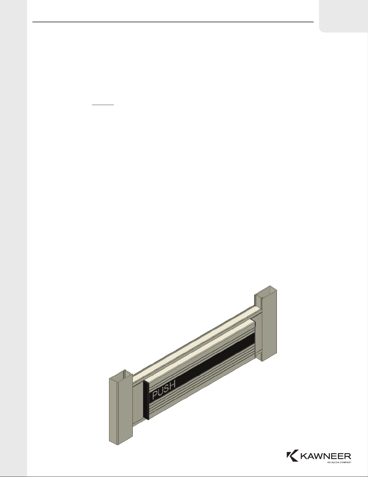
PANELINE®EXIT DEVICE
SERVICE INSTRUCTIONS
DOGGING INSTRUCTIONS AND LOCK CYLINDER INSTALLATION
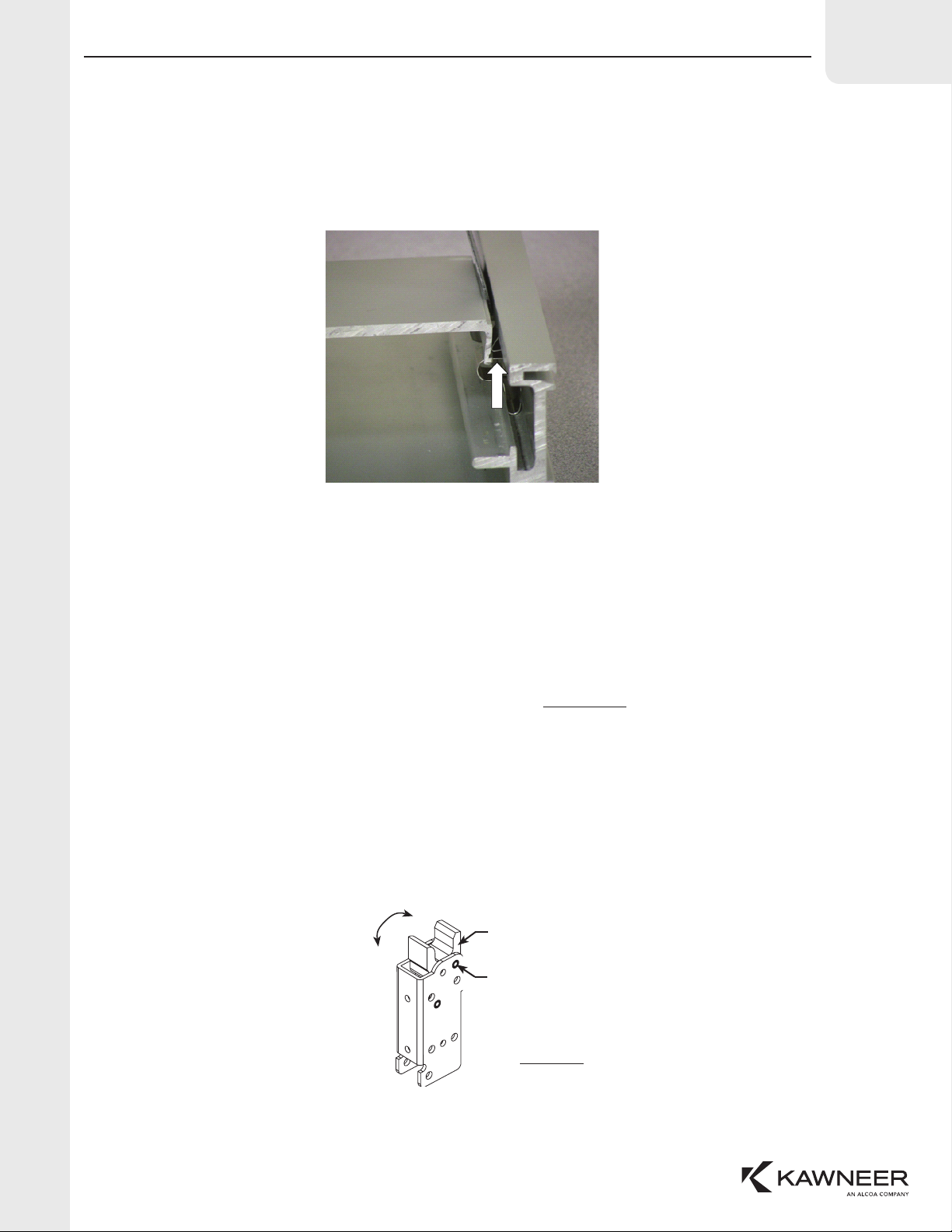
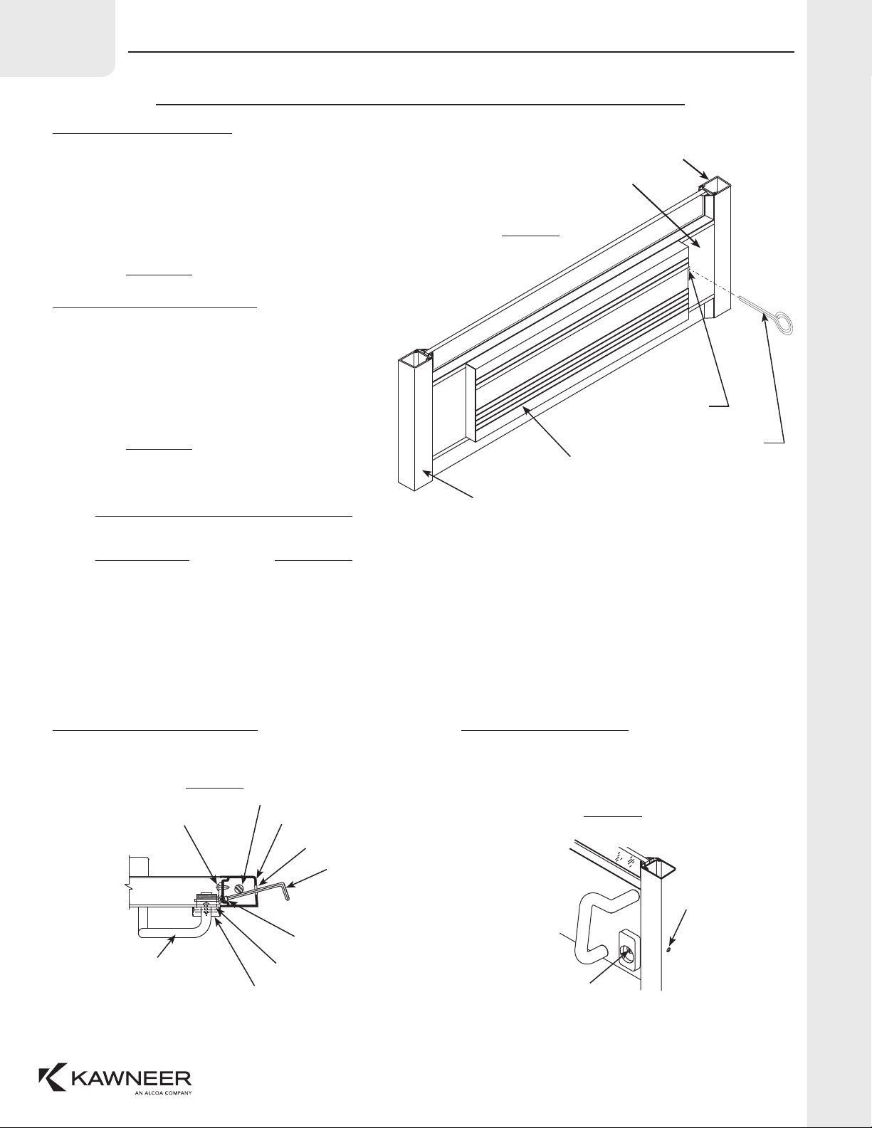
DOGGING INSTRUCTIONS
To secure the exit device in the unlocked (dogged) position,
follow this sequence:
1. Fully depress push panel.
2. Insert dogging hex key (provided) into the access hole
in the middle of the filler plate closest to the hinge stile.
(See Figure A)
3. Turn key one-quarter turn clockwise.
Figure A
LOCK STILE
PUSH PANEL
DOGGING SCREW
LOCATION
HINGE STILE
FILLER PLATE
7/32" HEX KEY
INSTALLING CYLINDERS BY OTHERS
THE FOLLOWING CYLINDER BRANDS MAY BE USED WITH KAWNEER’S PANELINE®CR90 EXIT DEVICE:
MANUFACTURER CAM NUMBER
ELKEM-VING 9001
SCOVILL (YALE) 1161
UNICAN (ILCO) 15-L4002-64
SUPERIOR A
SARGENT 13-0097
BEST IEC4
SCHLAGE B502-191
CORBIN / RUSSWIN A62
NOTE: CYLINDER MUST HAVE 0.950 CAM SWEEP. IF CAM SWEEP IS LONGER IT MUST BE FILED DOWN.
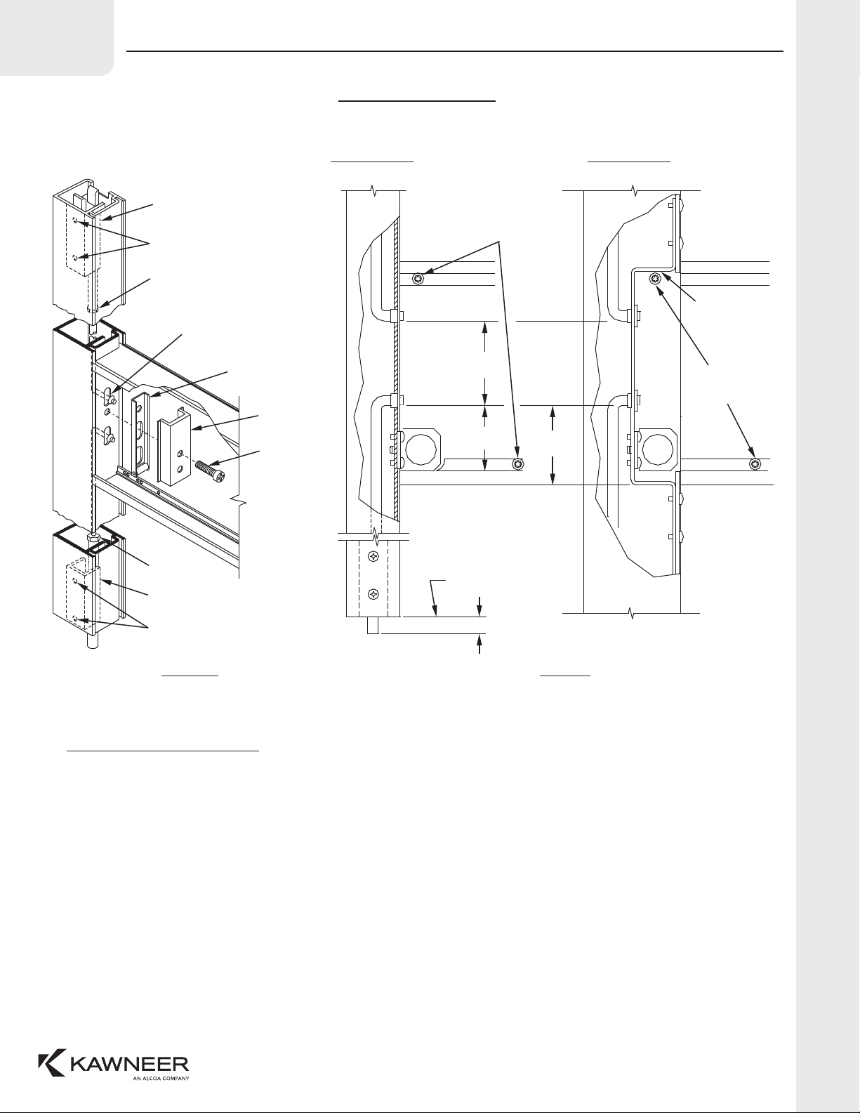
TO REMOVE LOCK CYLINDER
1. Open door and insert 9/64” allen wrench through hole in edge
of door stile at an angle that will engage the cylinder set screw.
Figure B
2. Loosen set screw about three full turns. Insert key part way
into cylinder key-way and turn to the left to remove lock cylinder.
EXIT DEVICE ROD
DOOR STILE
ACCESS HOLE
9/64" ALLEN WRENCH
CYLINDER SET SCREW
LOCK CYLINDER
OPTIONAL CYLINDER GUARD
DOOR PULL
CYLINDER BRACKET
TO REPLACE CYLINDER
3. Install replacement cylinder with key-way up.
NOTE: Length and tip contour of new cylinder cam must
match old cylinder cam. Old cam may be used if necessary.
4. Tighten cylinder set screw and check unlocking action
with key.
SET SCREW
ACCESS HOLE
KEY-WAY UP
Figure C
UN-DOGGING INSTRUCTIONS
To return the exit device to the normal operation,
follow this sequence:
1. Fully depress push panel.
2. Insert dogging hex key (provided) into the access hole
in the middle of the filler plate closest to the hinge stile.
(See Figure A)
3. Turn key one-quarter turn counterclockwise.
4. Release panel.