Kaya Instruments JetCam User manual

Flat Field Correction
CamerasJetCamIn
9201January
Sky Blue Microsystems GmbH
Geisenhausenerstr. 18
81379 Munich, Germany
www.skyblue.de
In Great Britain:
Zerif Technologies Ltd.
Winnington House, 2 Woodberry Grove
Finchley, London N12 0DR
www.zerif.co.uk
International Distributors
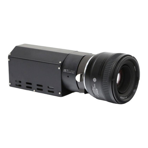
1
Contents
1Contents and Figures................................................................................................................................... 1
2Introduction................................................................................................................................................. 2
2.1 Overview .............................................................................................................................................. 2
2.2 Requirements........................................................................................................................................ 2
2.3 System connection................................................................................................................................ 3
3Using the DSNU and PRNU corrections.................................................................................................... 4
3.1 Dark field calibration process............................................................................................................... 4
3.2 Flat field calibration process ................................................................................................................ 5
3.3 User Set Control category .................................................................................................................... 7
3.3.1 UserSet - save and load camera configuration............................................................................... 8
Figures
FIGURE 1:JETCAM CAMERA FRONT VIEW WITH LENS ..................................................................................... 2
FIGURE 2:JETCAM CAMERA SYSTEM CONNECTION DIAGRAM ........................................................................ 3
FIGURE 3:JETCAM CAMERA SIDE VIEW W/O LENS........................................................................................... 4
FIGURE 4:DARK FIELD CALIBRATION STEPS .................................................................................................... 5
FIGURE 5:FLAT FIELD CALIBRATION STEPS...................................................................................................... 6
FIGURE 6:UNIFORM LIGHT SOURCE BEFORE VS.AFTER FLAT FIELD CALIBRATION......................................... 6
FIGURE 7:SAVING CAMERA PARAMETER CONFIGURATION.............................................................................. 7
Revision History
Version
Date
Notes
0.1
13/01/19
Initial Release
1Contents and Figures
Sky Blue Microsystems GmbH
Geisenhausenerstr. 18
81379 Munich, Germany
www.skyblue.de
In Great Britain:
Zerif Technologies Ltd.
Winnington House, 2 Woodberry Grove
Finchley, London N12 0DR
www.zerif.co.uk
International Distributors

2
2.1 Overview
The dark-field correction and the bright-field correction are both part of the flat field correction that
corrects for DSNU and PRNU, which both require two different calibration processes.
The flat field correction is used to improve the quality of the image by removing the artifacts that are
caused by fixed pattern noise and variations in the pixel-to-pixel sensitivity of the detector. A flat
field correction corrects for dark signal non-uniformities (DSNU), photo response non-uniformities
(PRNU) and/or artifacts caused by the illumination and illumination optics. These application notes
describe how to calibrate the flat field functions and how to use them to improve the quality of the
image. These functions are available in all JetCam series cameras.
Figure 1 : JetCam Camera front view with lens
2.2 Requirements
A computer with the following:
Processor with an Intel 64-bit architecture, or equivalent
An availably x4 (or x8 or x16) PCIe Gen 3 slot
Vision Point Application installation
JetCam Camera
Komodo Fiber Frame Grabber
Fiber cables (Multi or Single mode)
Fiber QSFP+ or/and SFP+ modules (depending on camera design)
2Introduction

3
Uniform light source
Solid cap
2.3 System connection
Please take a minute to read carefully the system connection instructions listed below.
1. Firmly insert the Komodo board to PCIe connector of the motherboard.
2. Align the QSFP+/SFP+ transceiver in front of the module’s transceiver socket opening and
carefully slide the QSFP+/ SFP+ transceiver into the socket until the transceiver makes contact
with the socket electrical connector.
3. Insert the fiber cable into the module, by firmly pushing each cable into the module, until you
will hear a click.
4. Connect the Power Adaptor to the JetCam power supply connector.
5. Turn the camera and the computer on and start your Vision Point software application.
An example of JetCam system connection is described in the image below:
Komodo Fiber
Frame Grabber
JetCam Camera Fiber cable
(up to 80 km)
Power
supply
Figure 2 : JetCam Camera system connection diagram
For more detailed information please refer to JetCam User Guide documentation.
Introduction

4
To make DSNU / PRNU correction, two pictures should be taken. For DSNU a reference image has
to be recorded in dark, with lens closed (offset should be boosted) or fully removed from the camera
and covered with a solid cap. To calibrate for PRNU a reference image has to be recorded with a
uniform illumination of around 40%. These two separate steps in the flat field correction are therefore
referred to as dark field calibration and bright field calibration, respectively.
Figure 3 : JetCam Camera side view w/o lens
3.1 Dark field calibration process
The dark field correction is the easiest one to calibrate. It only requires a reference image to be
recorded without illumination on the image sensor.
Follow this steps to perform dark field calibration process:
1. For dark field calibration, the light should be blocked from the sensor. This can be achieved by
removing the lens and covering the sensor with a solid cap or closing the lens with a cap
2. Set the “Field Calibration Mode” to “Dark” (1)
3. Start camera’s stream either in free run or by applying an external trigger
4. Initiate the selected calibration with “Field Calibration Start” command Execute (2)
5. Stop camera’s stream
6. Enable the Dark filed correction (3)
7. Start camera’s stream either in free run or by applying an external trigger
NOTE that Dark field calibration should be performed before Flat field.
3Using the DSNU and PRNU corrections

5
3
1
2
Figure 4 : Dark field calibration steps
3.2 Flat field calibration process
The choice of which light intensity to use for the bright field calibration requires a little bit more
thought. If you perform the calibration with a light intensity too close to camera saturation you might
compensate the camera too much and actually introduce more PRNU for low light intensities. If you
use a weak light intensity, the differences in photo response might be too small and you under-
compensate the sensor. In general a light intensity that gives a signal somewhere around 40% of the
sensor full scale should give the optimal result.
Follow this steps to perform flat field calibration process:
1. Prepare light source. Uniform light should be applied across the sensor. This can be achieved by
removing the lens and setting a uniform light source, such as diffused light or integrating sphere,
in front of the camera
2. Set the “Field Calibration Mode” to “Flat” (1)
3. Start camera’s stream either in free run or by applying an external trigger
4. Initiate the selected calibration with “Field Calibration Start” command Execute (2)
5. Stop camera’s stream
6. Enable the Flat filed correction (3)
7. Start camera’s stream either in free run or by applying an external trigger
NOTE that Flat field calibration should be performed after Dark field calibration has already be
performed for the selected camera settings.
Using the DSNU and PRNU corrections

6
3
1
2
Figure 5 : Flat field calibration steps
Notes:
1. Errors might show up when a sudden peak in intensity is present in the reference scene as the
correction is a low frequency correction.
2. There might be limits to the total difference that you will be able to correct for. The correction is
often achieved by applying a gain per pixel or pixel segment. If the available gain is not sufficient
to correct for the difference between the weakest and brightest illuminated pixel segment, a flat
field cannot be achieved.
Figure 6 : Uniform light source before vs. after flat field calibration
To summarize, depending on the flat field correction variant, reference images have to be recorded
in dark and in a bright field. Make sure the sensor is really dark when performing a dark field
calibration and performing a bright field calibration in a light intensity range around 40% of the sensor
full scale.
Using the DSNU and PRNU corrections

7
Note:
The PRNU and DSNU depends on exposure, gain, temperature and number of active fiber links. In
case the above conditions might change during camera operation, it is advised to pre calibrate the
system on several conditions and save them as different user sets. Load the user set if the conditions
have been changed. User set control is described in the next section.
3.3 User Set Control category
1
2
3
4
5
6
7
Figure 7 : Saving camera parameter configuration
Eight user sets are available for saving different camera parameter configurations. In addition, a
“Default” UserSet is available so it will be possible to revert back to default factory settings.
1. Selection between the different available user configuration
Default –Factory settings
UserSetX - Available user sets in non-volatile memory
2. Load the configuration of the selected user set
3. Save the configuration to the selected user set
4. Selection of the power up configuration
Non-volatile memory is available for user usage. Data save to this memory space will not be erase
upon camera power-down.
5. Execute an erase of the entire user memory on the camera
6. Selection of the memory page for saving
7. Execute a save to the selected memory page
Using the DSNU and PRNU corrections

8
Characteristics and restrictions:
1. Up to 65536 bytes can be saved into camera's non-volatile memory.
2. All data will be erased in 1 burst.
3. Data can be saved in bursts of 256 bytes each time. All 256 should be filled either with valid
or padding data.
4. If data is loaded before erase operation is performed (1 time for all data), this data may be
corrupted.
5. Data can be read at any time. (It is best not to read non-volatile memory while camera is
streaming).
6. The access to non-volatile memory will be performed via GeniCam interface:
Operation sequence.
3.3.1 UserSet - save and load camera configuration
The following steps describe the sequence of saving and loading user set parameter configurations
for a specific camera, using Vision Point application:
Save User Set:
1. Calibrate the desired camera parameters in “Camera” tab.
2. Open “User Set Control” category
3. Select the desired “UserSetSelector” numeration as UserSetX (X in range of 1-8).
NOTE: “Default” user set contains factory settings and is not rewritable.
4. Execute “Save User Configuration” command.
Load User Set:
1. Select “UserSetSelector” to the desired UserSetX (X in range of 1-8).
2. Execute “Load User Configuration” command.
3. Press “Refresh” (located in the bottom of the project window).
4. In order to determine the user set configuration with which setting the camera will power up,
set the desired user set in “User Set Default Selector” to UserSetX (X in range of 1-8).
NOTE: “Default” user set will load camera’s factory settings.
Using the DSNU and PRNU corrections

9
The following function call sequence should be performed to achieve successful User Non-Volatile
new memory save:
KYFG_SetGrabberValueInt(camHandle, UserMemoryPageSelector, <page[255..0]>)
KYFG_ExecuteCommand(camHandle, UserMemoryBulkErase)
1.
2.
KYFG_ExecuteCommand(camHandle, UserMemoryPageSave)
uint8_t buffer[256]; uint32_t bufferSize = sizeof(buffer);
KYFG_CameraReadReg(camHandle, 0x30300, buffer, &bufferSize);
uint8_t buffer[256]={0,1,2,3/*...*/}; uint32_t bufferSize = sizeof(buffer);
KYFG_CameraWriteReg(camHandle, 0x30300, buffer, &bufferSize);
3.
4.
Figure 8 : Non-Volatile memory save function call sequence
1. “UserMemoryBulkErase” – erase all user non-volatile memory
2. “UserMemoryPageSelector” – select page[255..0] in memory (256 bytes for each page)
3. “UserMemoryPageAll” – array of 256 bytes to load data of specified page
4. “UserMemoryPageSave” – save selected page to non-volatile memory
NOTE: Firmware update may erase the saved user sets, and may change camera’s “Default” settings.
Using the DSNU and PRNU corrections
Sky Blue Microsystems GmbH
Geisenhausenerstr. 18
81379 Munich, Germany
www.skyblue.de
In Great Britain:
Zerif Technologies Ltd.
Winnington House, 2 Woodberry Grove
Finchley, London N12 0DR
www.zerif.co.uk
International Distributors
Other manuals for JetCam
3
Table of contents
Other Kaya Instruments Digital Camera manuals

Kaya Instruments
Kaya Instruments JetCam User manual

Kaya Instruments
Kaya Instruments JetCam User manual

Kaya Instruments
Kaya Instruments IRON SDI Series User manual

Kaya Instruments
Kaya Instruments JetCam User manual

Kaya Instruments
Kaya Instruments IRON CoaXPress User manual

Kaya Instruments
Kaya Instruments IRON SDI User manual