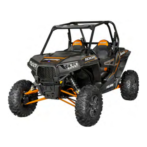
KAYO MOTOR HY110AT User manual

ZHE JIANG KAYO MOTOR CO., LTD
WWW.KAYOMOTO.COM
1
AT110 model
Maintenance Manual

ZHE JIANG KAYO MOTOR CO., LTD
WWW.KAYOMOTO.COM
2
Compilation Illustration
This maintenance manual introduces the maintenance adjustment procedure, disassembly
and assembly essentials, inspection and maintenance points, troubleshooting methods and
maintenance technical data of AT110 model (ATV) (four-wheel all-terrain vehicle) in detail, with
detailed graphic data attached to guide the operation.
Please carefully read this manual and conduct inspection and repair in accordance with the
standard operating practices, which can effectively extend the service life of each part, improve
the performance of the engine and the reliability of the whole vehicle.

ZHE JIANG KAYO MOTOR CO., LTD
WWW.KAYOMOTO.COM
3
Content
Chapter 1: Maintenance Information
Chapter 2: Vehicle Body & Plastic Parts
Chapter 3: Check and adjust regularly
Chapter 4: External Components of the Engine
Chapter5: Engine
ZHE JIANG KAYO MOTOR CO., LTD
Note: Please understand that the contents in this maintenance
manual which subject to change due to vehicle improvement,
upgrading will not notify again. The actual condition of the
vehicle shall prevail in the maintenance.

ZHE JIANG KAYO MOTOR CO., LTD
WWW.KAYOMOTO.COM
4
Unit Conversion Covered in the Manual
Item
Unit Conversion
Pressure
1kgf/cm2=98.0665kPa;1kPa=1000Pa
1PSI=0.0689kgf/cm2
1mmHg=133.322Pa=0.133322kPa
Torque
1kgf·m=9.80665N·m
Volume
1mL=1cm3=1cc
1L=1000cm3
moment of
force
1kgf=9.80665N
Length
1in=25.4mm
Danger/warning/caution
Please read the following explanation carefully. It emphasizes the special
meaning of the words "danger", "warning" and "attention". Special attention should
be paid to the prominent meaning in the whole vehicle and engine maintenance.
Danger: Means to be alert to high danger
Warning: Indicates caution against moderate danger
Caution: Indicates concern for minor hazards
However, it is important to note that the "hazards" and "warnings" contained in
this maintenance manual cannot cover all potential hazards in the process of engine
use and maintenance.Therefore, in addition to the "danger" and "warning"
regulations, maintenance personnel must also have basic mechanical safety
knowledge. If the operator is not sure to complete the entire maintenance operation
process, please consult more experienced senior technicians.
Maintenance information
1.1 Notes for Operation
1.2 Vehicle identification code
1.3 Main parameter table
1.4 Maintenance parameters table
1.5 Tighten torque
1.6 Lubrication and sealing
1.7 Cable, hose and cable wiring diagram
1.1 Notes for Operation
Safety precautions
1. Work clothes (jumpsuits), hats, safety boots must be worn. When necessary, safety protective

ZHE JIANG KAYO MOTOR CO., LTD
WWW.KAYOMOTO.COM
5
equipment such as dustproof glasses, dustproof masks and gloves should be put on to protect
yourself from injury.
2. Because the exhaust gas contains harmful components, it is prohibited to operate the engine
in closed places and places with poor ventilation for a long time.
3. When the engine is shut down, the temperature of the engine and muffler is very high, so that
it cannot be touched before cooling to avoid burns.
4. The battery solution (dilute sulfuric acid) is a corrosive agent, which may cause burns and
blindness when it touches the skin and splashes into the eyes.In case of accidental contact with
battery solution on clothes and skin, flush with plenty of water immediately;in case of accidental
contact with battery solution on eyes, please;Flush with plenty of water immediately and go to
the hospital in time for treatment.Batteries and battery solutions should be kept strictly and must
be placed in a safe place out of reach of children.Battery charging is able to produce flammable
and explosive hydrogen, once there is a fire or electric spark near, there is an explosion
risk.Therefore, please charge in a well-ventilated place.
5. As gasoline is flammable and explosive, fireworks are strictly prohibited in the work site.Watch
not only for open flames, but also for electric sparks.Vaporized gasoline is at risk of explosion.
Please choose a well-ventilated site for operation.
6. Do not let the rear-wheel, clutch or other rotating parts and movable parts clamp hands and
clothes at any time during maintenance.
7. When two or more people work together, they must continuously greet each other to ensure
safety.
Disassembly and assembly Note
1. Components, lubricants and lipids must be made from genuine parts of Kayo brand
or recommended parts designated by Kayo.
2. After the vehicle is disassembled, the parts of each system shall be sorted out and
kept separately to ensure that the parts can be put back to their original position.
3. Please clean the dirt and dust of the vehicle before maintenance.
4. The gasket, o-ring, piston pin retainer, opening pin and other parts must be
replaced after disassembly.Replace the lock nut according to damage situation after
removal.
5. When the elastic baffle, spring, and steel wire baffle are disassembled, if the
opening is too large, it will cause irreversible plastic deformation, resulting in the
failure of parts, which will be easy to fall off after re-assembly.Please do not use
already loose, lose the flexibility of this kind of article to replace new one in time.
6. After the parts are disassembled and checked, clean them before measurement
and blow off the cleaning agent with compressed air.Oil or grease should be applied
on the movement surface before assembly.
7. When disassembly, necessary parts shall be inspected, relevant data measured
and even pictures taken.So that the assembly is able to revert to the previous state of
disassembly.
8. Bolts, nuts and screw fasteners must first be threaded with 2~3 turns of thread,
and then tightened on the diagonal in accordance with the principle of from big to

ZHE JIANG KAYO MOTOR CO., LTD
WWW.KAYOMOTO.COM
6
small and from inside out according to the prescribed tightening torque.
9. Rubber parts should be inspected for aging during disassembly and replaced in
advance if necessary.Rubber parts are not resistant to gasoline and kerosene
corrosion, try not to allow volatile oil, grease kind of touch.
10. The recommended grease should be applied or injected into the designated parts
as required by the maintenance manual.
11. Correct special tools should be used for disassembly and assembly.
12. When deep groove ball bearing is disassembled, it adopts the disassembly
method of internal ring force, so the removed bearing shall not be used again, and
shall be replaced in time.
Deep groove ball bearings can be used finger rotation, if abnormal sound, stuck,
bearing should be replaced.
Bearing axial.If the radial clearance is too large, it shall be replaced.
Bearing and the original on the body or diameter of the original pressure to fit, after
the disassembly of the fit is not tight should be replaced.
13. The bearing should be coated with machine oil or grease before assembling.One -
sided bearings need to pay attention to the direction of assembly.Open type,
double-sided dust-proof cover bearing in the assembly of the manufacturer's logo,
the size of the face outward installation.
14. When installing elastic baffle, one side with chamfer should be turned out.Do not
use loose retainers.Rotate the elastic baffle after assembly and make sure the baffle
is installed in the groove.
15. After assembly, please check whether the fasteners are tightened and working
properly.
16. Brake fluid, gasoline and oil will corrode the coating surface, plastic parts, rubber
parts, etc.Special care should be taken to prevent the above liquid from touching
during disassembly and assembly.
17. The oil seal shall be installed outward with one side marked by the manufacturer.
Check to make sure the spring coil inside the oil seal is intact.
Note lip crimping, broken, crack can not be used.
Smear grease on the oil seal surface to prevent burrs from scratching the oil seal lip.
18. When installing hose parts, the hose must be checked to the root of the
joint.Tubing clips must be installed to the hollow of the pipe.Loose hose must be
replaced during installation.
19. Pay attention to dust prevention during vehicle maintenance, and do not
introduce dust and dirt into the engine, fuel tank and brake oil pressure system.
20. The gasket material attached to the joint surface of each box body of the engine
can only be assembled after cleaning.To remove the contact mark on the surface, it
must be polished evenly with oil stone.
21. The lasso should not be excessively twisted or bent.Deformation and damage to
the cable will create a lag.
22. When assembling cap parts, the cap with groove must be installed into the
groove.

ZHE JIANG KAYO MOTOR CO., LTD
WWW.KAYOMOTO.COM
7
Engine Running-in
The engine has many relative moving parts, such as piston, piston ring, cylinder body,
crankshaft, crank, connecting rod, intermeshing transmission gear and so
on.Therefore, in the early use of these parts, the specification of running-in is
necessary.The run-in can make the relative moving parts adapt to each other, correct
the working clearance, and form a good smooth friction surface that can withstand
large loads.Only when the engine is well-run can it have excellent performance, more
stable reliability and extend the service life of the engine.
The recommended running time of the engine is 20 hours, and the specifications are
as follows:
0~10 hours: avoid continuous operation in the state of 1/2 throttle opening, and
change speed at the same time, it is not recommended to operate in a fixed throttle
position for a long time.After working for 1 hour, stop the engine to cool down for 5
to 10 minutes to avoid rapid acceleration.
10~20 hours: avoid long operation when the throttle is over 3/4 open. Use the
accelerator freely, but not full throttle.
Note:
As per the daily maintenance provisions during wear and repair, troubleshooting in
time;
After the end of the grinding, the engine for 20 hours of grinding before maintenance
can enter the normal driving stage
1.2 VIN
Vehicle Model
HY110AT(AT110)
VIN
ENGINE NO.
Inscription position See attached figure:
1) VIN on Chasis
2) Vehicle name plate
3) Engine No.

ZHE JIANG KAYO MOTOR CO., LTD
WWW.KAYOMOTO.COM
8
1
1.4 Main Parameters
No.
Item
1
TRADE MARK
KAYO
2
MODEL
HY110AT
3
NAME
ATV 110cc Sport ATV
4
COMPANY
Zhejiang Kayo Motor Co., Ltd
1
Dimension(L*W*H) (mm)
1380*880*930
2
Height of Handle bar (mm)
930
3
Width of Handle bar (mm)
730
4
Height of Vehicle Tail (mm)
700
5
Seat Height (mm)
635
6
Ground Clearance(mm)
90
7
Wheel Base(mm)
900
8
Front wheel base
700
3
2
Main dimension parameters
1

ZHE JIANG KAYO MOTOR CO., LTD
WWW.KAYOMOTO.COM
9
Engine parameters
No
.
Item
1
Starting method
Electric start
2
Engine type
Horizontal Single cylinder, four stroke, air
cooling
3
Air distribution
SOHC/Chain drive
4
Cylinder diameter ×stroke(mm)
52.4*49.5
5
Compression ratio
9.0 :1
6
Lubrication method
Pressure + splash lubrication
7
Oil pump type
Rotor type
8
Lubricating oil filter type
Full flow filter rotary,Paper filter core
9
No. of Engine oil
SAE15W-40
10
Cooling
Air Cooling
11
Coolant
/
12
Air filter
Sponge filter cartridge
13
Carburetor
Flat suction plunger type (JINGKE
PZ22/EPA)
14
Fuel Tank Capacity
2L
15
Clutch
Dry automatic clutch
16
Variable speed mode
1+1 Foot shifting, with shift protection.
17
Shift Gear
One forward gear, one reverse gear
18
Shift mode / sequence
R~N~D
19
Deceleration
ratio
Forward Gear D
Reverse Gear R
Primary
Deceleration ratio
Clutch hub gear / primary transmission
tooth
Single stage
deceleration ratio
Forward gear
ratio
Forward gear ratio
Total speed ratio
Chasis
20
Driving sprocket ratio
37/13
21
Output form
Chain drive, rear wheel drive
22
Brake
Front and rear disc brake
9
Rear wheel base
640
10
Turning radius
1650
11
Steering angle(Degree)
38°±2°
12
Dry Weight(kg)
97.4±2
13
Curb Weight(Battery + Fuel)(Kg)
102
14
Max. Speed Km/h
(Speed limitation) 40

ZHE JIANG KAYO MOTOR CO., LTD
WWW.KAYOMOTO.COM
10
23
Suspension
Double rocker independent type
24
Frame
Welded steel tube sheet
Lubricating device
Item
Standard
limited
Engine oil
capacity
Change oil
800mL
(
No oil filter replaced
)
-
Change oil
800mL
(
oil filter replaced
)
Full capacity
800mL
-
Recommended engine oil(See Original File)
Specilly used for 4-stroke motorcycle, if
want to use other oil replace SAE-15W-40
Should used within following mentioned
range
·
API Classify: SG or higher engine oil.
·
SAE Specification:Choose start from
left side table according to outside
temperature.
Oil pump rotor
Internal and external rotor
0.07 mm~0.15mm
0.2mm
Clearance between outer rotor
0.03 mm~0.10mm
0.12mm
Oil pump rotor end clearance
0.023 mm
~
0.055 mm
0.12 mm
Oil pressure
1500r/min,90℃时 200 kPa ~400kPa,
Generally 240 kPa
6000r/min, 90℃600 kPa ~700kPa,
Generally 600 kPa
Intake system (see engine part)
Cooling device (no)
Wheel(front and rear are the same)
Item
Standard
limited
Rim pulsation
Vertical
1.0mm
2.0mm
Horizontal
1.0mm
1.8mm
Tyre
Groove depth
~
3.0mm
Air Pressure
4.0 PSI
~
Brake System
Item
Standard
limited
Front Brake (1 drag 2)
Brake disc thickness
3.5mm
3mm
Brake handle stroke
5~10mm
~
Brake disc strength
400N*m
~
Rear Brake
Brake disc thickness
3.5mm
~
Brake handle stroke
10~20mm
~
Viscosity
grade
Tempretuare

ZHE JIANG KAYO MOTOR CO., LTD
WWW.KAYOMOTO.COM
11
Brake disc strength
500 N*m
~
Ignition device
Item
Standard
Ignition methord
CDI Ignition
Sparking plug
Type
Resistive spark plug
Standard
ATR7C/(torch)
Spark plug gap
0.6~0.7mm
Spark
characteristics
>8mm,1 atmospheres
Ignition advance angle
High voltage
package
resistance
Primary Resistance
0.43~0.57Ω
Second Resistance
10.1~11KΩ
Peak voltage
Ignition coil
Primary
>150V
Pulse generator
2V
Light/Instrument/Switch
Item
Standard
Relay Chip Fuse
15A
Light
Front Lelt & Right
Light
12V*3W*2
Rear light / brake
light
LED
Shift Gear Indication
Light
LED
Valve + Cylinder head (See Engine Section)
Cylinder + Piston + Piston Ring + Crank Link(See Engine Section)
1.5 Fastener tightening torque
Note: When you install thread, you must manually bring 2~3 thread.
Tightening torque at the designated part
The entire vehicle part
No.
Item
Installation
Position
Bolt
specification
Grade
TorqueN*m
1
Engine
Rear power
bolt
M8
10.9 Grade
37~50
2
Upper power
M8
10.9 Grade
37~50

ZHE JIANG KAYO MOTOR CO., LTD
WWW.KAYOMOTO.COM
12
bolt
3
Lower power
bolt
M8
8.8 Grade
18~25
4
Suspensio
n
Front and rear
Suspension
bolts
M10*1.25
8.8 Grade
35~45
5
Upper rocker
shaft
M10*1.25
8.8 Grade
35~45
6
Lower rocker
bolt
M10*1.25
10.9 Grade
58~71
7
Fork shaft
M12*1.25
8.8 Grade
50~60
8
Brake
Rear disc brake
mounting
M8
8.8 Grade
18~25(Blue
thread
adhesive )
9
Front Dics
brake
mounting
M6
10.9 Grade
15~20
10
Disc brake
pump
Mounting
M8
10.9Grade
29~35
11
Front Brake
Tee Installation
M8
8.8
18~25
12
Rear Axle
Rear Axle
Mounting
M12*1.25
8.8
55~65
13
Big Nut
M27*1.5
80~90
14
Chain bolt
M6
8.8
8~12
15
Steering
Clip locking
bolt(Inside
hexagonal)
corners)
M8
10.9
18~25
16
Steering
column locking
M8
8.8
18~25
17
Lower
Pressure block
mounting bolt
M10*1.5
10.9
50~60
18
Electrical
devices
Battery Box
Installation
M8
8.8
15~20
19
Muffler
fastening
M8
8.8
15~20
20
Pressurizer
high pressure
M6
8.8
7~11

ZHE JIANG KAYO MOTOR CO., LTD
WWW.KAYOMOTO.COM
13
package
21
Fuel tank,
Vehicle
Body,
Plastic
parts
Fuel Tank
Installation
M6
8.8
7~11
22
Fuel Tank
Switch
M6
8.8
7~11
23
Pedal
Installation
M8
8.8
18~25
24
Steel Pedal
M6
8.8
8~12
25
Plastic Flat
head
TM6
7~11
26
Self tapping
pins for
connection
headlight with
Plastic Parts.
ST4.2
3~5
Tightening torque at the specified location - Engine section ( See Engine section )
Engine repair tool (See Engine section)
Engine-specific tools (See Engine section)
1.6 Lubricating grease, sealant
No.
Smear Position
Function
Grease
1
Upper and lower rocker arm
dust cover
Lubrication
XHP222
2
Upper and lower rocker ball
head seat
3
Steering column base
4
Left and right steering knuckle
joint with wheel hub
5
Rear fork mounting shaft
6
Rear flat fork inner liner
7
Rear axle lining pipe
8
Rear axle bearing oil seal
9
Steering column clamp block
Note: The handle bar should to be glued first when install the grip
Engine running material and installation accessories (see engine part). Engine
operating materials include lubricant (Engine oil), grease (yellow oil), etc.
Installation accessories include sealant, thread glue and so on.
1.7 Cable Connection Layout

ZHE JIANG KAYO MOTOR CO., LTD
WWW.KAYOMOTO.COM
14
Main Cable
Front brake tubing
Throttle Cable
Rear brake tubing
Choke cable

ZHE JIANG KAYO MOTOR CO., LTD
WWW.KAYOMOTO.COM
15
Headlight connector
Functional switch connector
Switch lock connector
Reverse display connector
Neutral display connector
Emergency flameout switch connector
Brake cable connector
Power
anode
Power cathode
Magneto connector
Gear display connector
Rectifier regulator connector

ZHE JIANG KAYO MOTOR CO., LTD
WWW.KAYOMOTO.COM
16
Ignition
Coil
CDI
Rectifier
Regulator
Rear
lamp

ZHE JIANG KAYO MOTOR CO., LTD
WWW.KAYOMOTO.COM
17
2 Vehicle Covers
2.1 Maintenance information
2.2 Mounting torque
2.3 Disassembly and assembly of seat cushion, front and rear protectives, front and
rear mud plate, head cover, rear body, left and right protective plate, front body, left
and right plastic pedals and left and right pedals
2.1 Maintenance information
Work notes:
1. When replacing the overlays with the warning signs affixed and riveted on the
vehicles, the corresponding marks should be correctly and completely completed
according to the original ones.
2. This chapter describes the disassembly sequence of vehicle body panels, and
refers to this chapter when it is necessary to disassemble the related panels when
repairing the internal parts of the vehicle.
3. This chapter only describes the disassembly and assembly. If the problem of cable,
tubing and cable alignment is involved in the process of disassembly and assembly,
please refer to the cable layout chart.
2.2 Mounting torque
M8 bolt:18~25N*m
TM6 Large headed bolt :7~11 N*m
M6*bolt:8~12 N*m
2.3 Dismantling and assembling of head cover, handle bar, seat cushion, whole
vehicle plastic parts (front and rear fender, rear body, left and right footrest guard,
front body), front guard assembly, left and right plastic parts of pedals, left and
right pedals.
2.3.1Head cover
Disassemble
1. Remove the fixing bolts 1 and 2 (2 in
symmetrical position).
2. Push the head cover in the direction
shown in the figure. Remove the head
cover after the buckle is loosened.
(Note: the buckle on the head cover is
easy to break and operate carefully.)
Assemble
Follow the reverse sequence and
reverse direction of the disassembly.
After installation, pay attention to
checking whether the cushion is
installed in place and reliable.

ZHE JIANG KAYO MOTOR CO., LTD
WWW.KAYOMOTO.COM
18
2.3.2 Handle Bar
Disassemble
1, when dismantling the direction, first
disconnect the vehicle power supply.
2. Use scissors to cut the plastic tie, and
pull out the main plug of the
multi-functional switch, the plug of the
flameout switch and the plug of the
brake wire in turn.
3. Release the handle bolt of the disc
brake with the tool and remove the
brake handle.
4, the front brake dismantling the rear
brake.
5,Pull out the air door line according to
the graphic direction, then remove the
choke cable.
6,Screw the accelerator cap bolts with
tools and remove the throttle cable.
7,Remove the pressing bolts, remove
the upper block and remove the handle
bar.
1/2
Functional switch
Rear Brake
Front Brake
Throttle perch
Choke Switch
Flameout Switch

ZHE JIANG KAYO MOTOR CO., LTD
WWW.KAYOMOTO.COM
19
Assemble
Follow the reverse sequence of dismantling, and check to see if the installation is in place.
(Note: 1) After the installation of the handle bar, the flameout switch connector, multi-functional
switch connector and brake connector must be checked to prevent misconnection and loosening.
2, Check the choke cable, throttle cable is installed in place.
3, The front brake and rear brake is suitable for installation angle, and the handle bar is
referenced to the vehicle wiring diagram.
2.3.3 CUSHION ASSEMBLE
DISASSEMBLE
1. Press the tail of the cushion and pull the seat hook at the same time.
2. Lift up the back of the cushion and pull the cushion back.
ASSEMBLE
Follow the reverse sequence and reverse direction of the disassembly. After
installation, pay attention to checking whether the cushion is installed in place and
stable. (Note: The front hook of the seat cushion must be installed in the limit of the
frame, and the limiting column of the seat cushion must be installed in the limit of
the frame installation).
2.3.4 Front guard assmebly
Disassembly
1. Remove the installation bolts of the
front guard assembly in turn.
2. Remove the front guard assembly.
Assembly
Cushion hook
Mounting bolt

ZHE JIANG KAYO MOTOR CO., LTD
WWW.KAYOMOTO.COM
20
Installation is done in reverse order.
(Note: If bolts and nuts are damaged, please replace new parts of the same specification in time.)
2.3.5 Vehicle plastic parts
Disassemble
Disconnect the electric lock plug, the neutral indicator lamp plug, the reverse indicator lamp plug,
the left and right headlight plug.
Remove the fixed bolts 1/2, 3/4, 5/6, 7/8, 9/10 in turn. Note (2/4/6/8/10 on the other side of the
vehicle)
Unscrew the oil tank cover and remove the whole vehicle plastic parts. (Note: During
the maintenance process, the handle bar must be removed first when dismantling the vehicle
plastic parts.)
安装
Assemble
Oil tank
Cap
1
2
3
4
5
This manual suits for next models
1
Table of contents
Other KAYO MOTOR Offroad Vehicle manuals

KAYO MOTOR
KAYO MOTOR AU125 User manual

KAYO MOTOR
KAYO MOTOR AU200 User manual

KAYO MOTOR
KAYO MOTOR BULL 150 User manual

KAYO MOTOR
KAYO MOTOR JACKAL 200 User manual

KAYO MOTOR
KAYO MOTOR A180 User manual

KAYO MOTOR
KAYO MOTOR STORM 150 User manual

KAYO MOTOR
KAYO MOTOR AU110 User manual

KAYO MOTOR
KAYO MOTOR AT125-B User manual

KAYO MOTOR
KAYO MOTOR AY70-2 User manual

KAYO MOTOR
KAYO MOTOR FOX 70 User manual